Got the flaps rigged and the electric motor connected…time for some fun! Click on the video below to see.

Got the flaps rigged and the electric motor connected…time for some fun! Click on the video below to see.
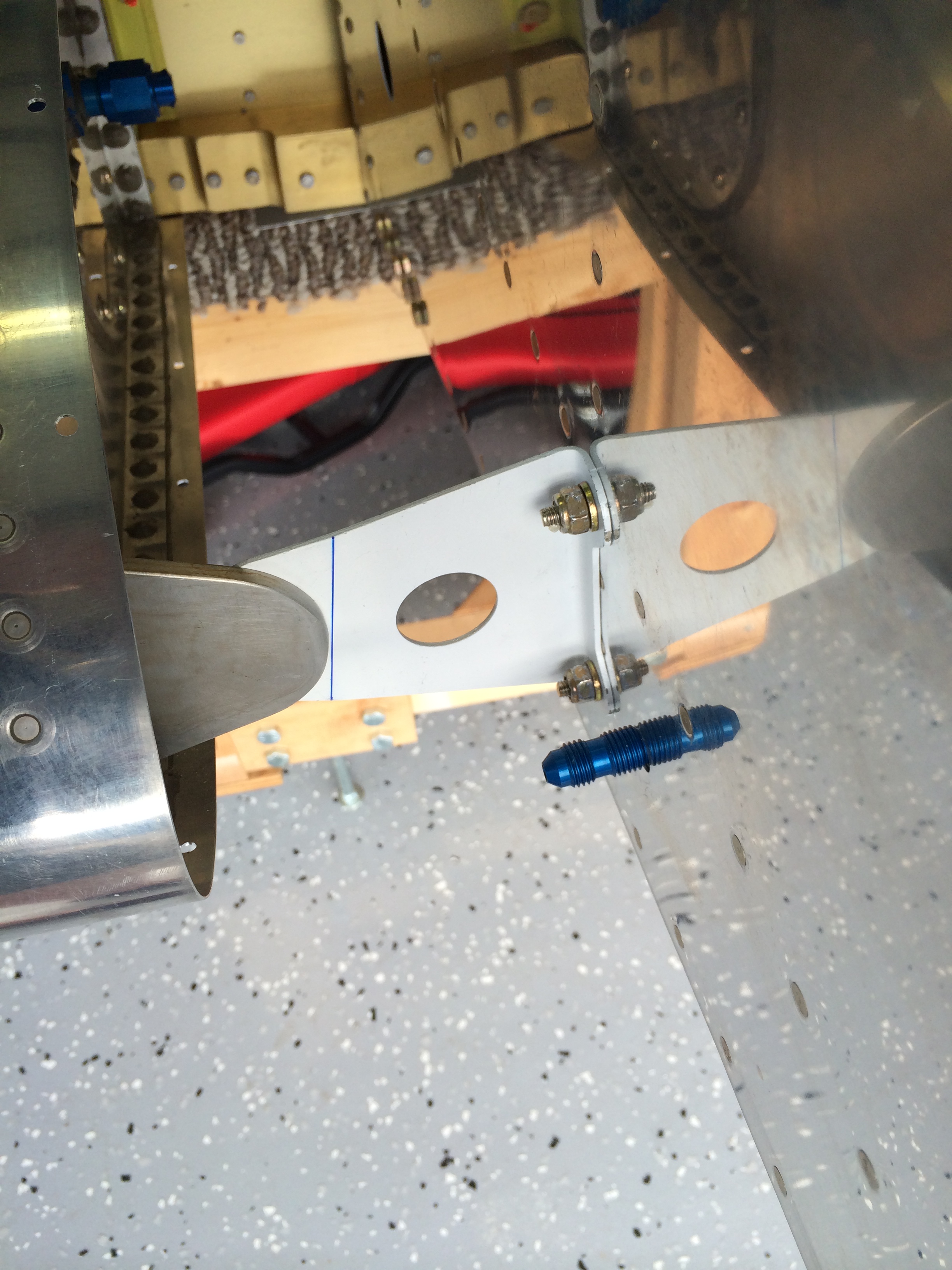
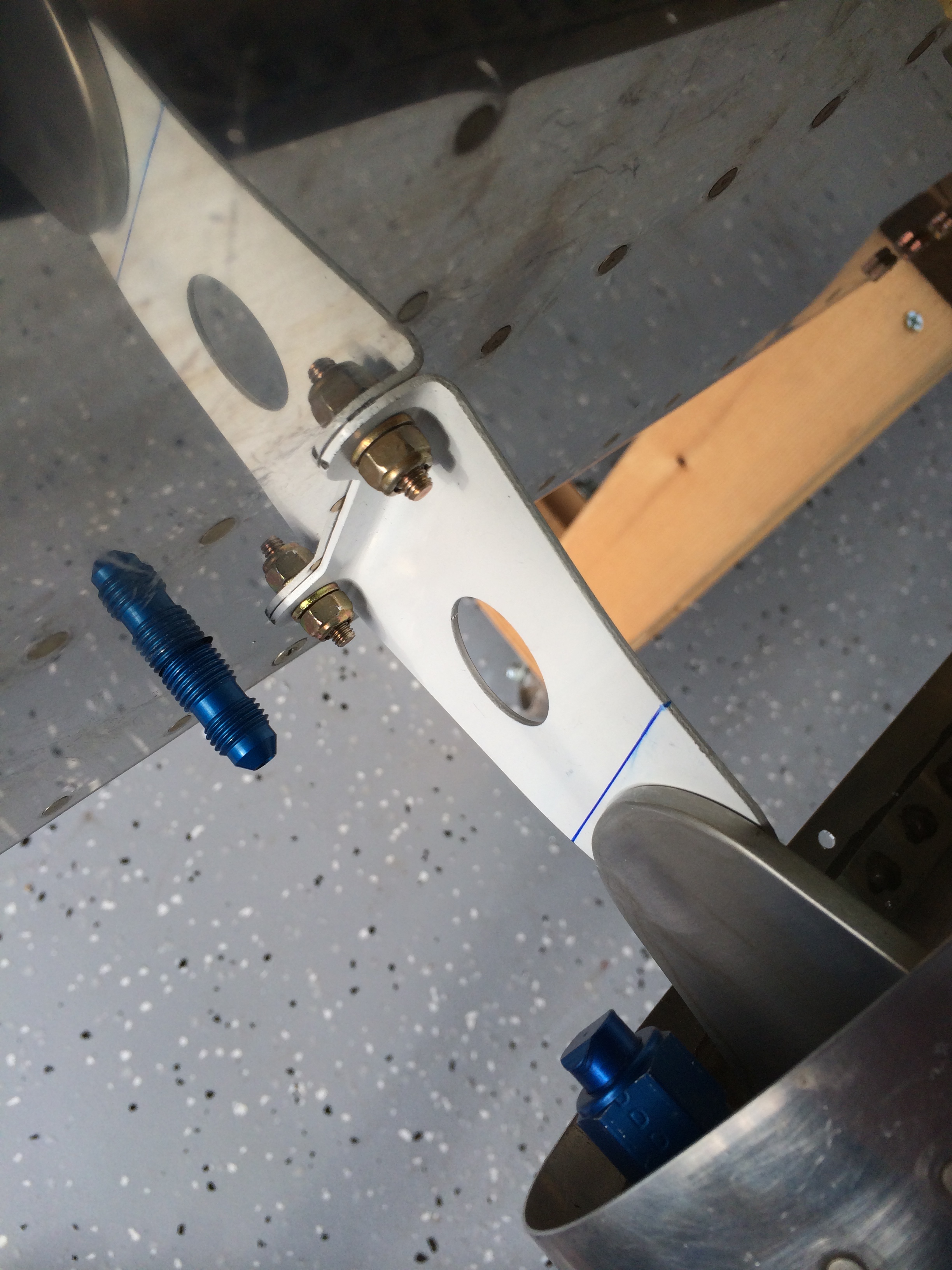
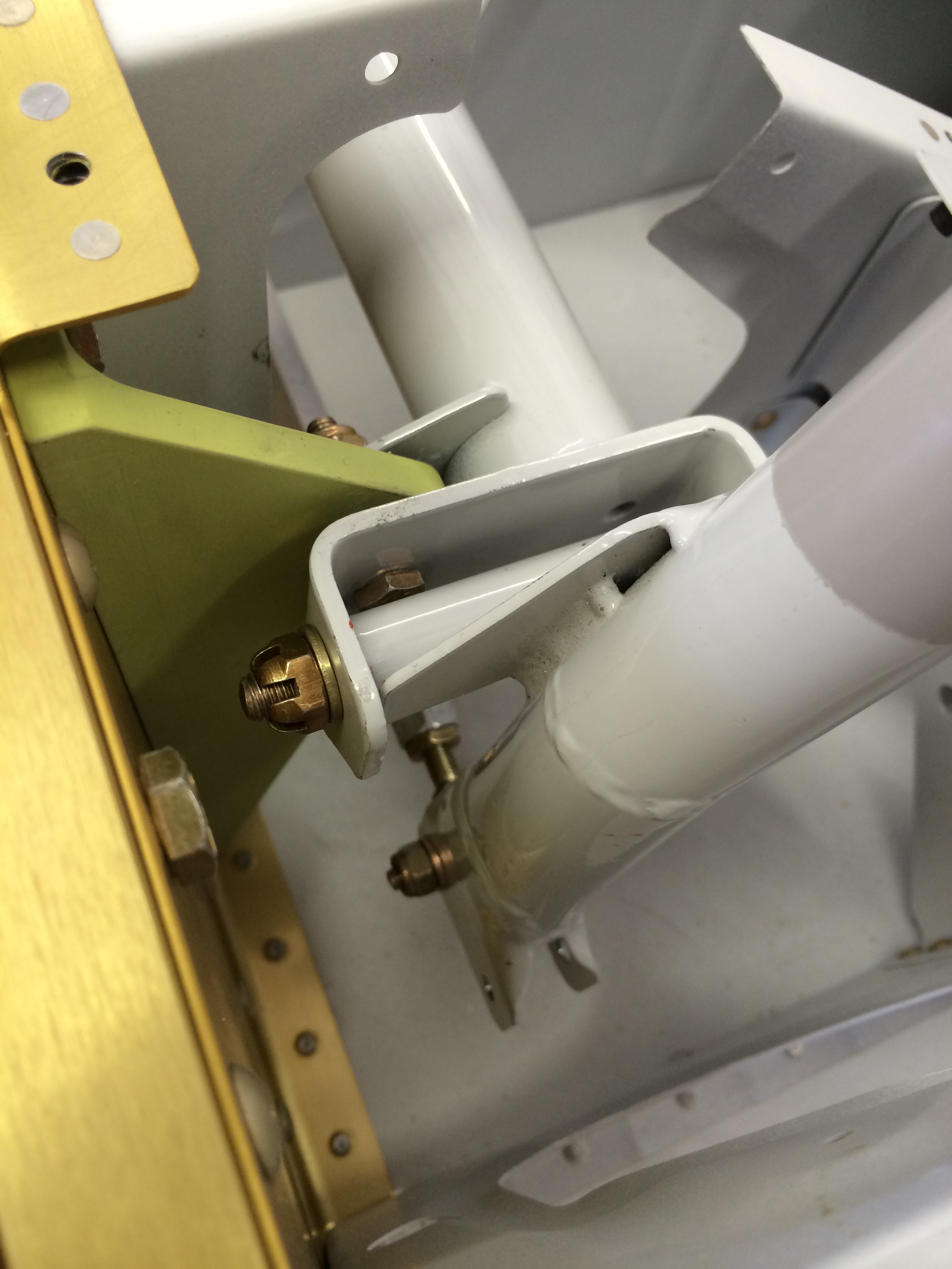
I was a little nervous about fitting these two steel brackets that support the forward inboard end of each fuel tank, because I slipped up and had already fitted them to the fuselage before installing the wings. The brackets are supposed to be clamped to the tank angles – the big D-shaped piece of aluminum on the end of the tank – then match-drilled to the fuse. I was concerned that they might end up being misaligned, but fortunately that turned out to not be the case.
 The right bracket fit almost perfectly after being bent according to plans. A little adjustment with the vise and hand seamers got it just right…
The left bracket wasn’t quite so easy to fit…I had to tweak it a bit to get it flush with the tank angle, but in the end it came out fine.
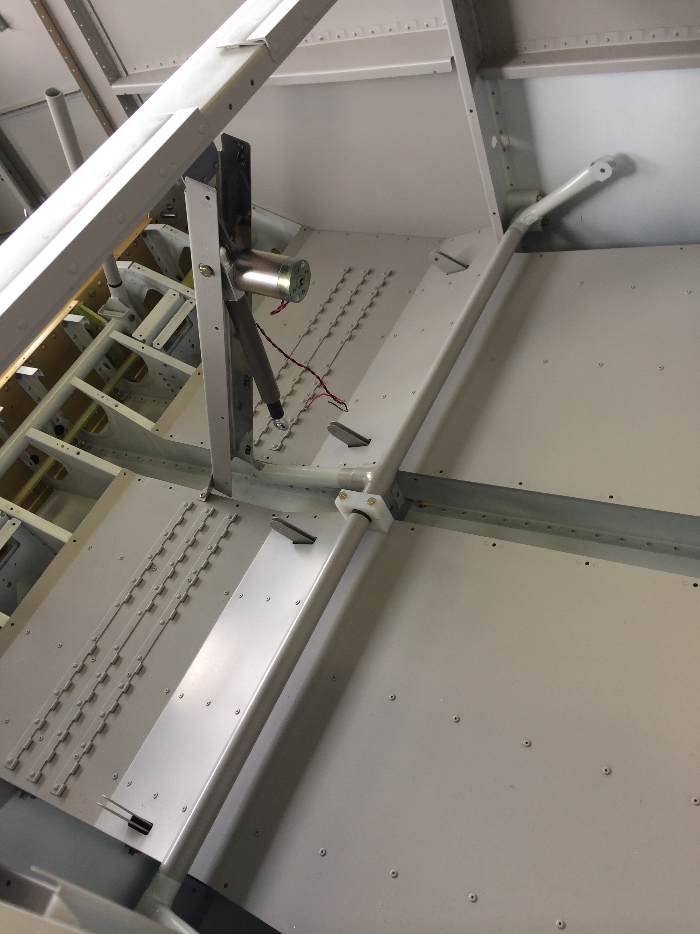
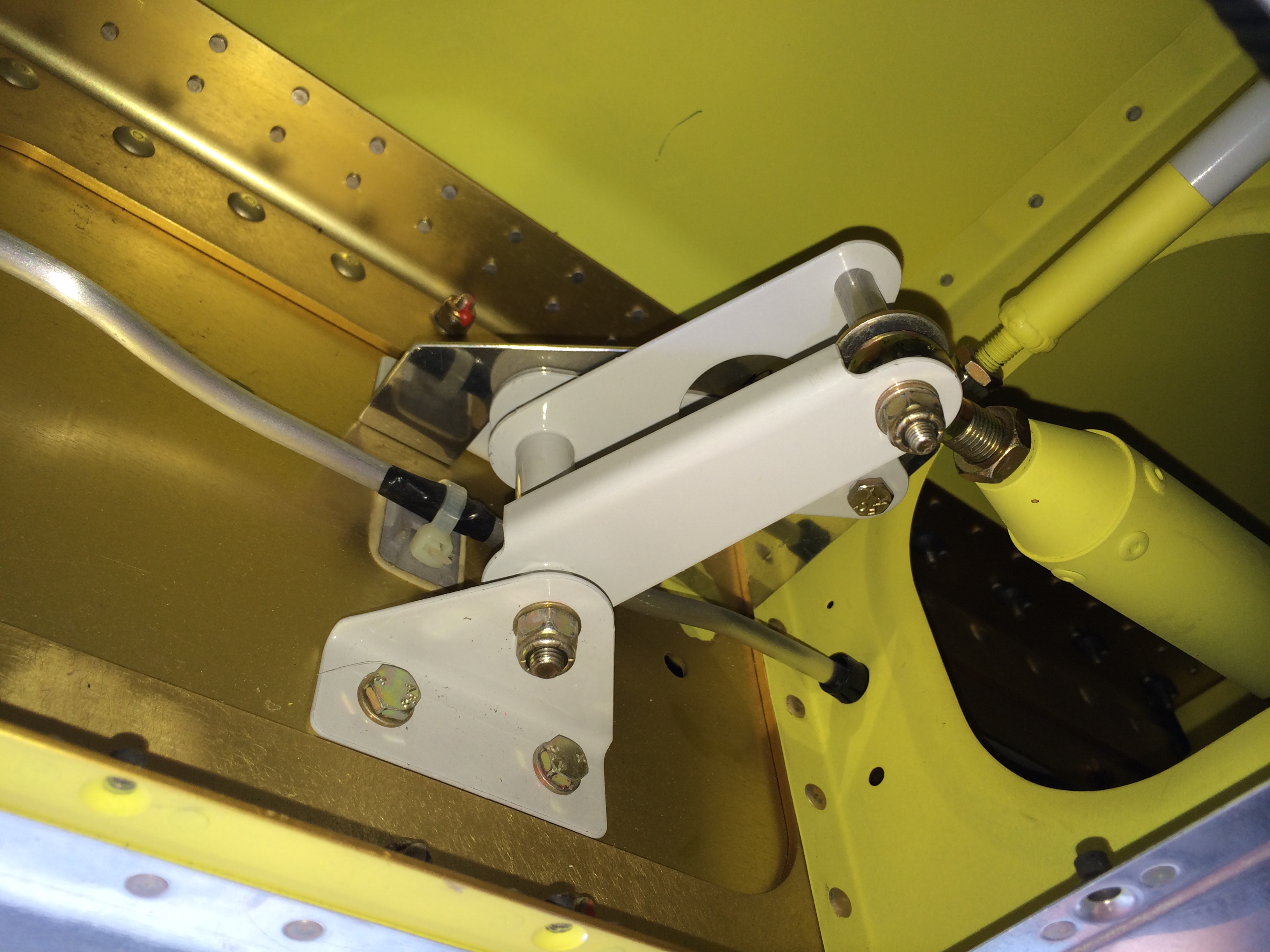
The last major task I had to take care of with the wings installed was rigging the flaps. To do that, I temporarily installed the flap motor and flap actuator arm.
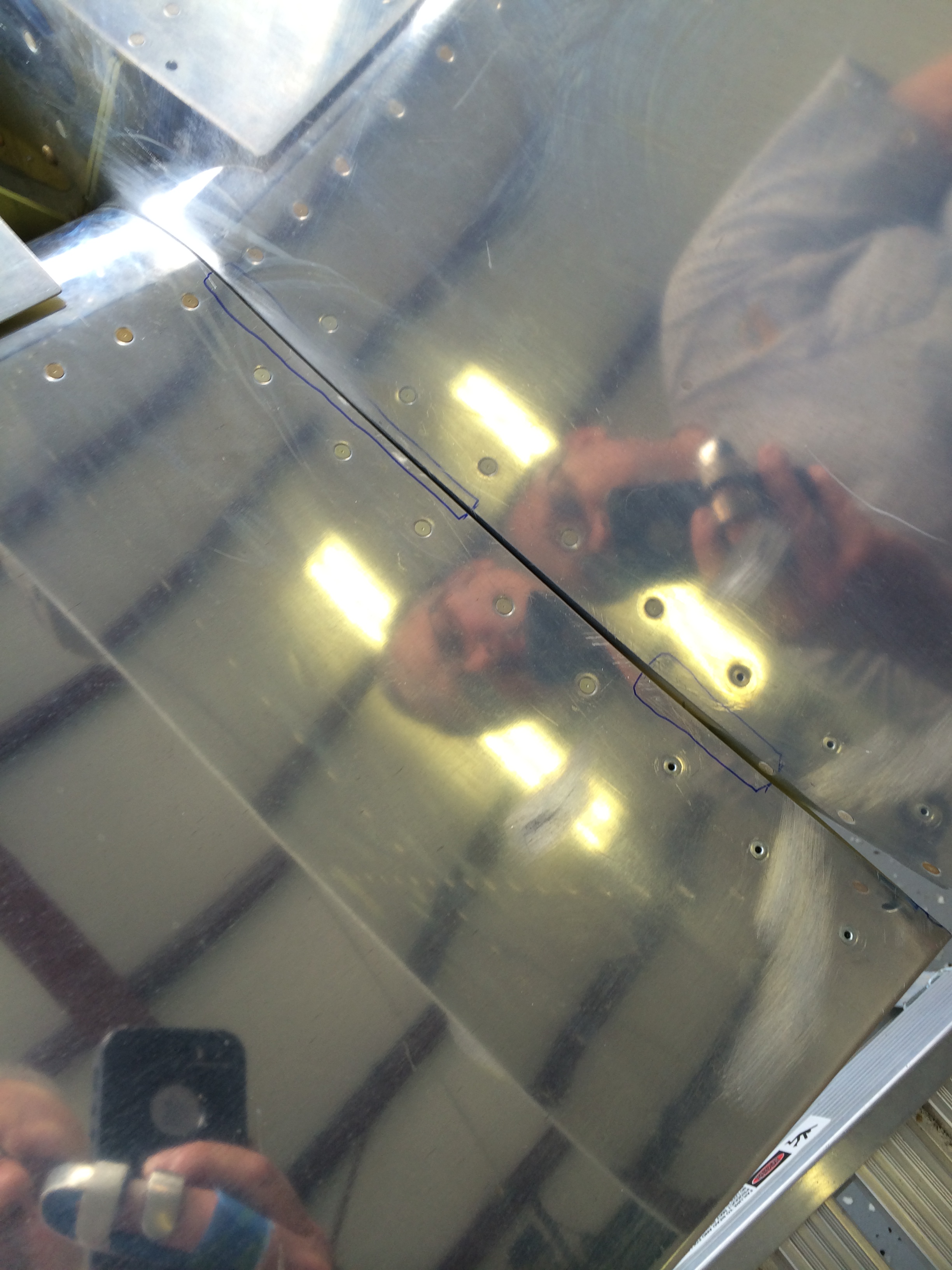
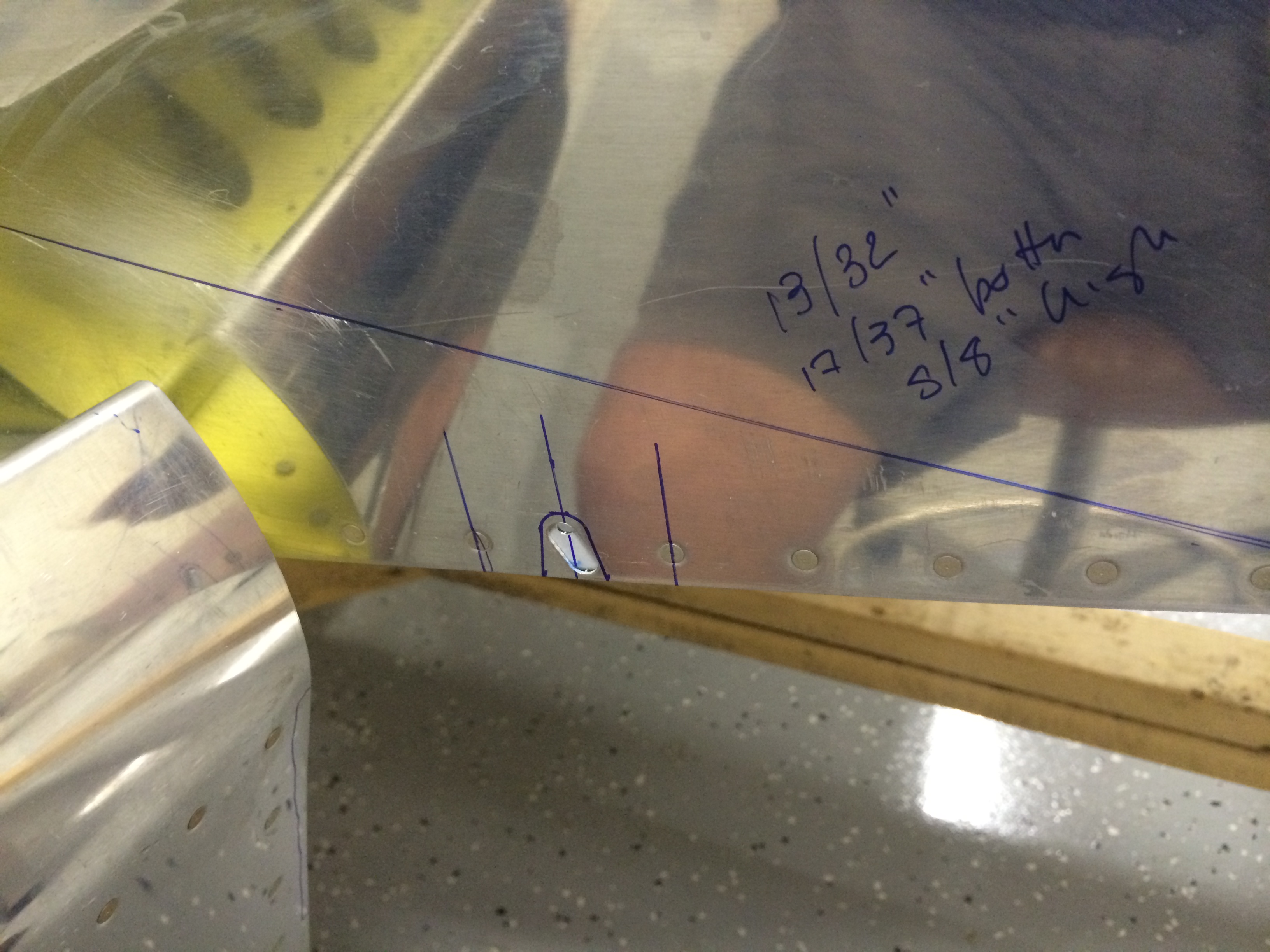
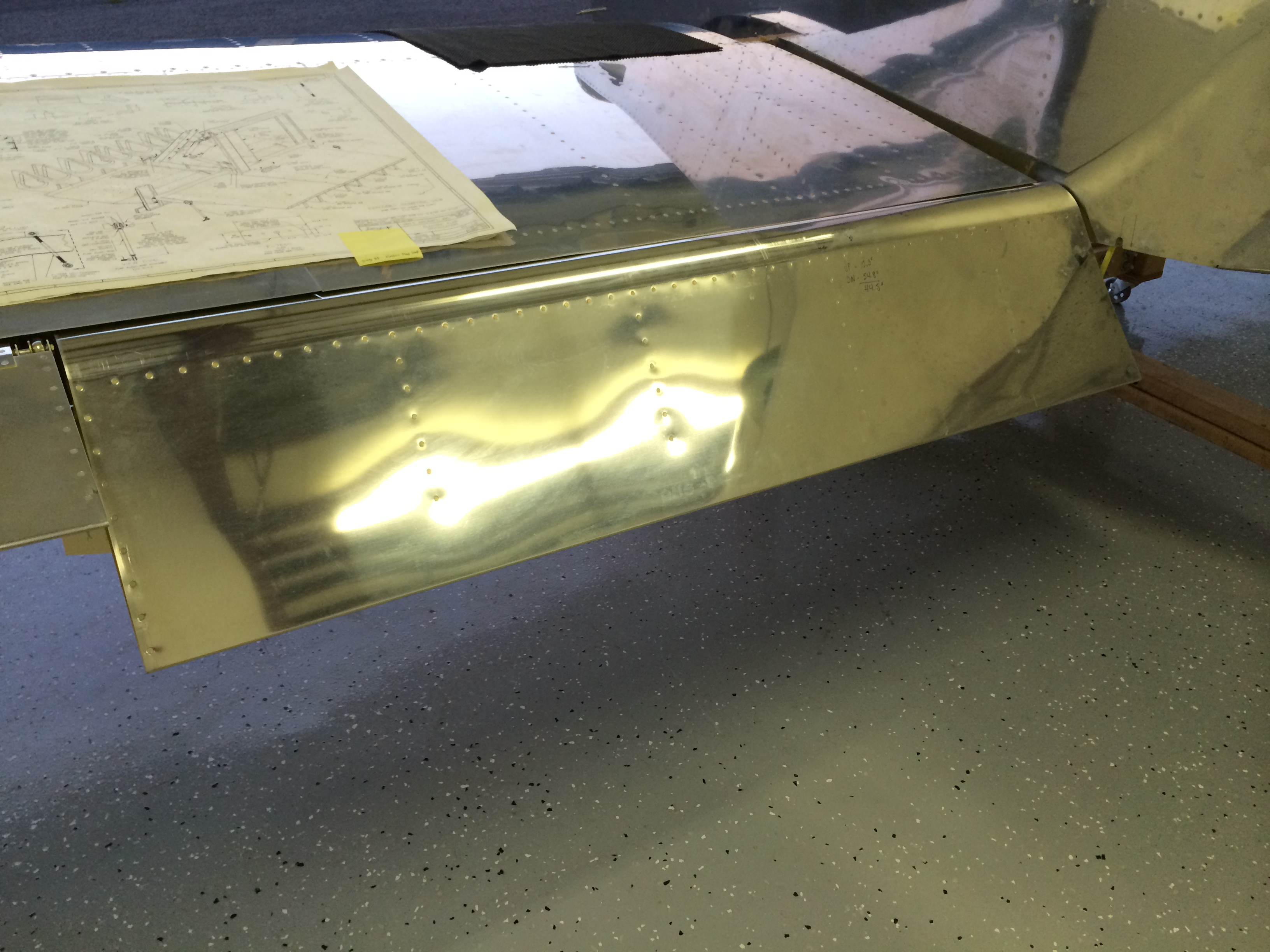
I installed the flaps, and found that the left flap rubbed against the fuselage side skin. The areas outlined in blue are where I had to file off some of the flap skin to eliminate the interference.
The most tricky part was figuring out exactly how much to enlarge the fuselage side skin openings to accommodate the movement of the flap actuator arms as they move the flaps up and down. Here’s my first guess with some rough measurements roughed out from a friend’s RV-7.
I also laid out holes on the belly skins and started trimming…
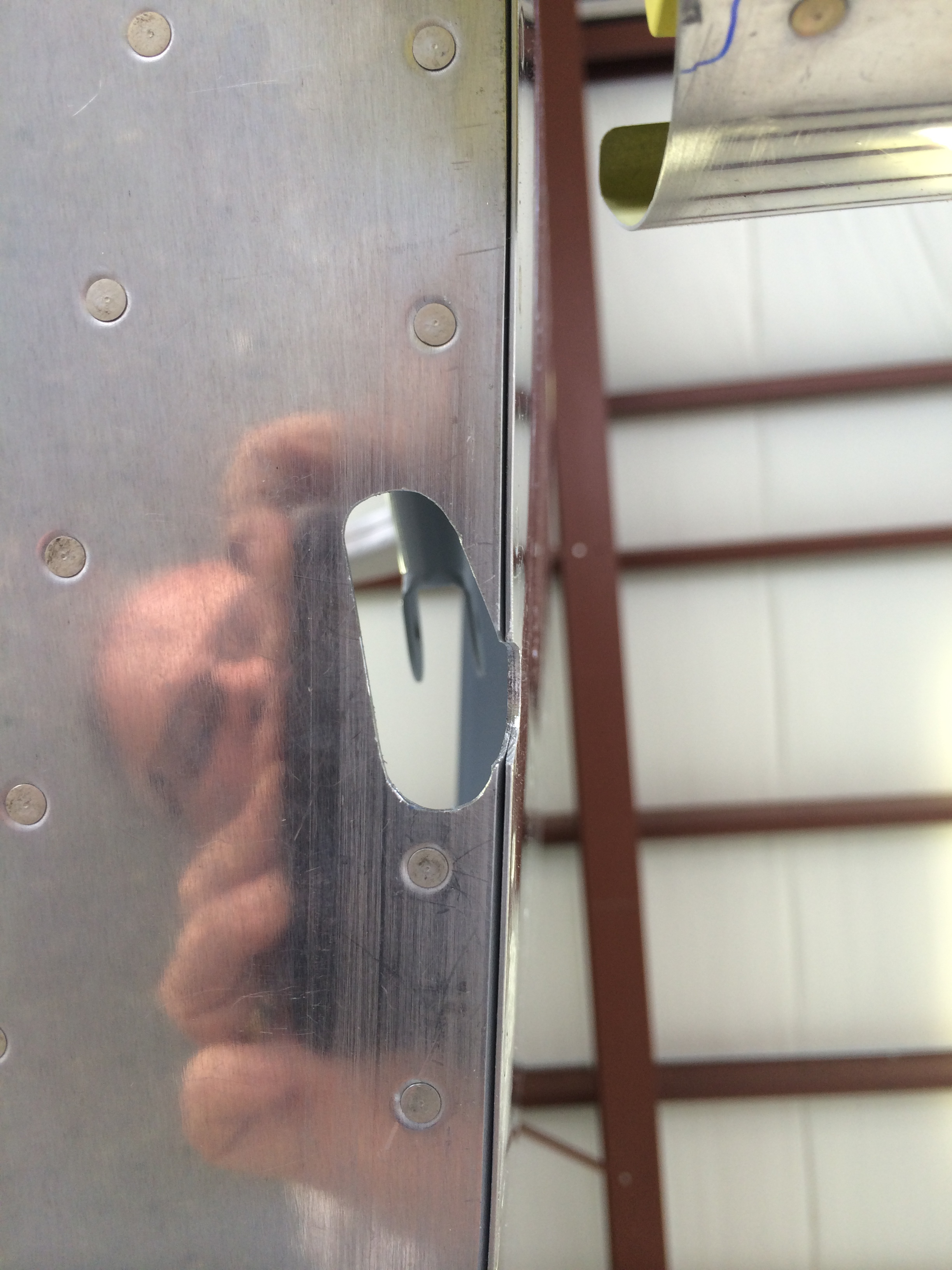
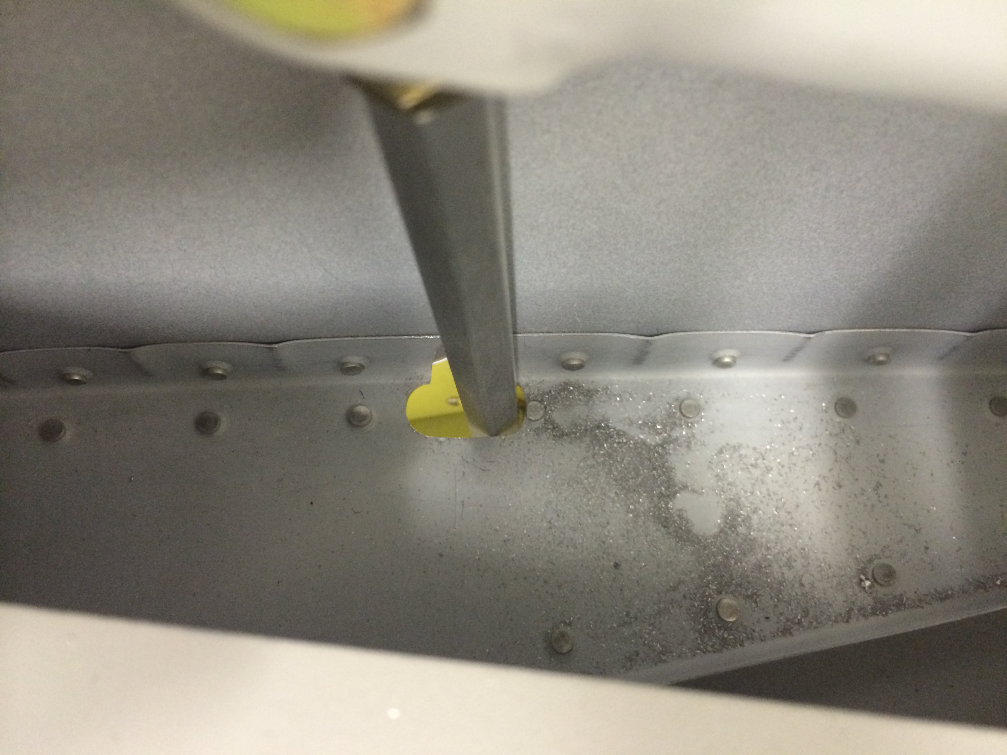
This was a very iterative process…move the flaps, check for interference, and trim the holes as appropriate. It took several hours to get the holes for both actuator arms to move freely.
I used my handy Harbor Freight battery booster to run the flap motor…

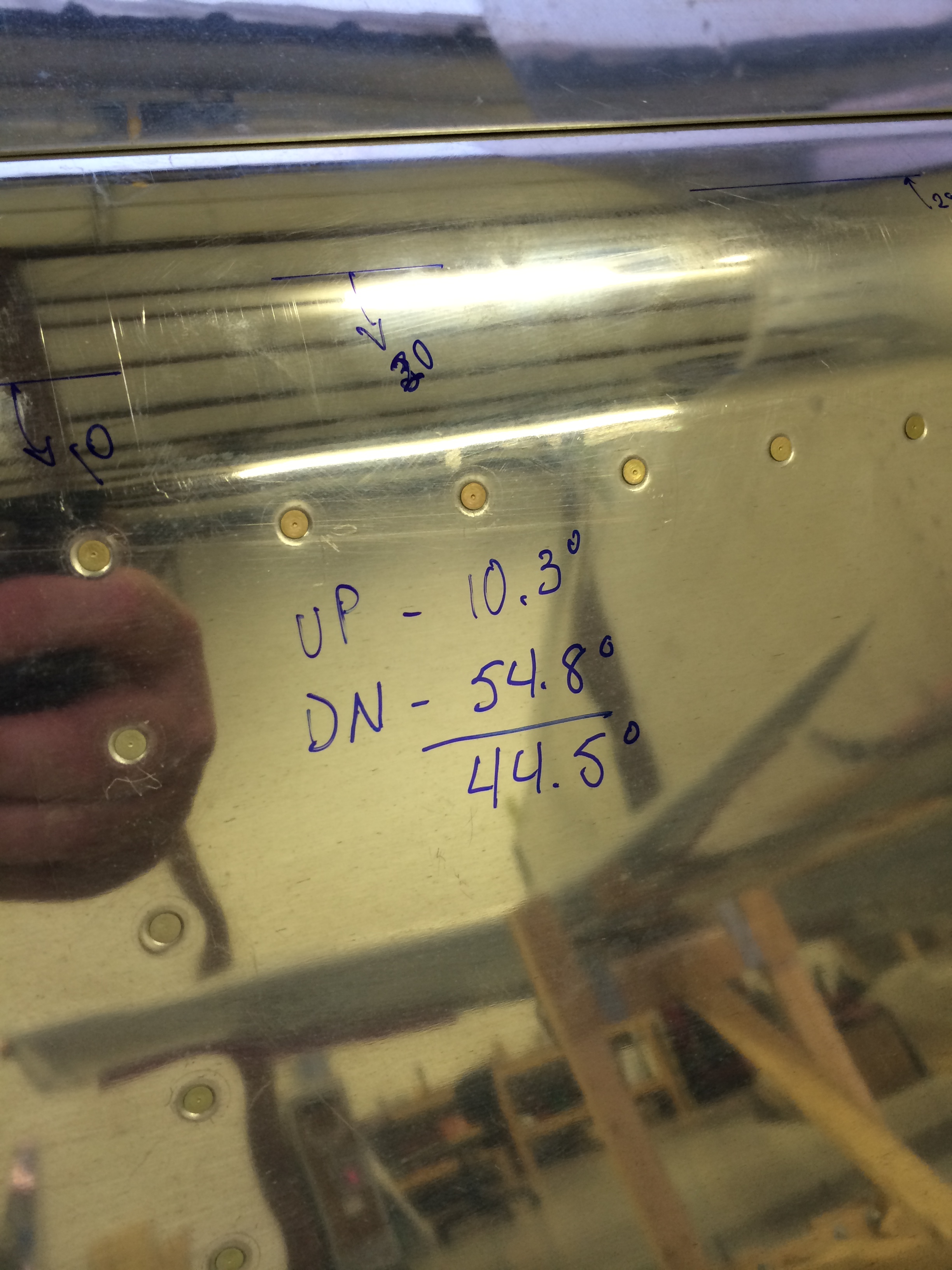
As I was checking the holes for interference, I was also checking for the proper range of flap motion. Vans says the flaps should go down no more than 45 degrees, so used my digital level to measure the flap angle both at full up and full down – subtracting full up from full down shows slightly less than 45 degrees on both sides – perfect!
And here’s the end result on the right flap…looks great!
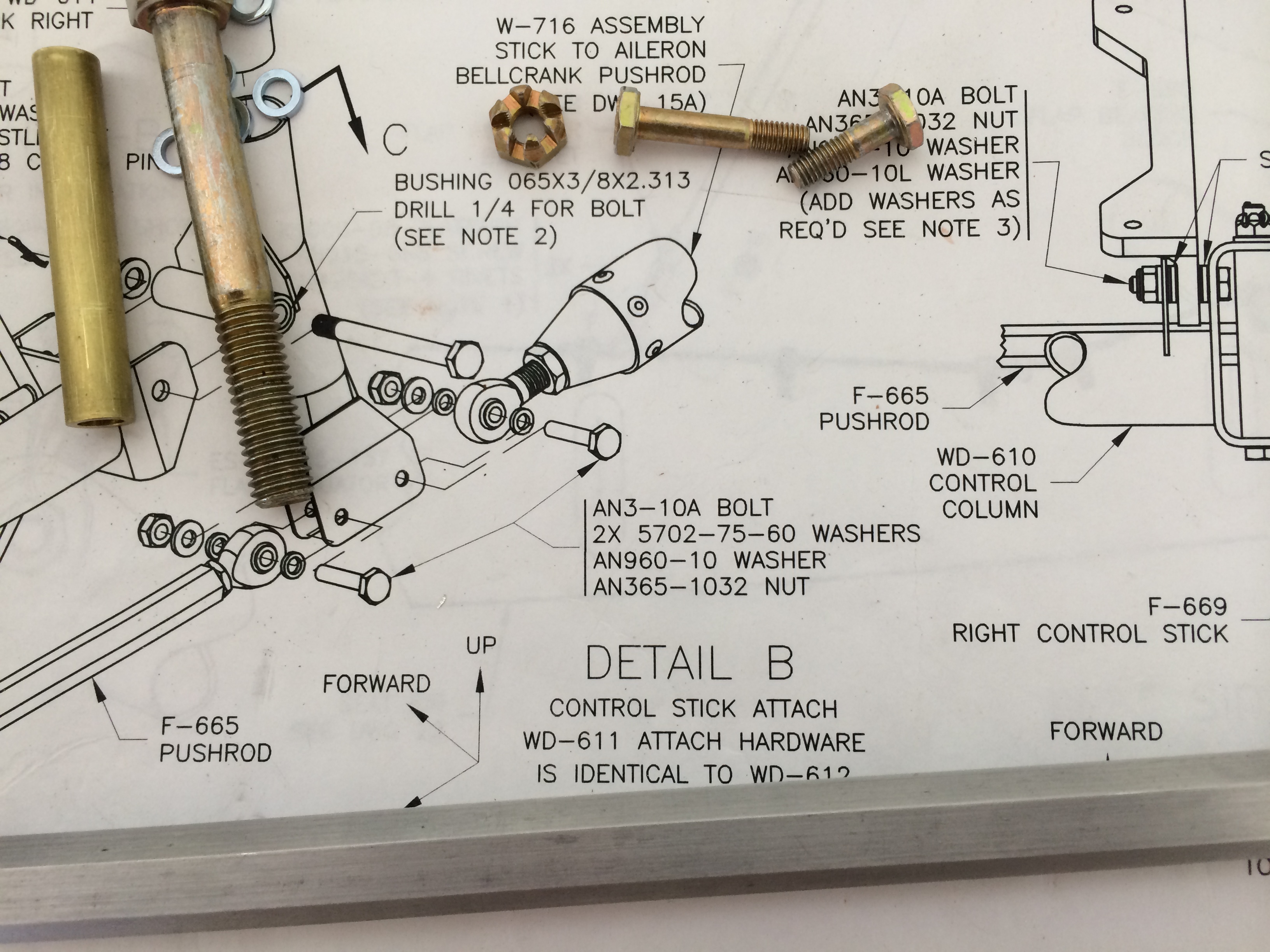
Next up on the list of things to be done is rigging the ailerons and aileron pushrods to the control sticks. There’s nothing too difficult here, but like a lot of other tasks at this stage, there’s a lot of tweaking and adjusting involved.
There are two pushrods for each aileron, one from the control stick to a bellcrank in the wing, and another from the bellcrank to the aileron itself. I had already adjusted both bellcrank-to-aileron pushrods when I built the wings, but I wanted to recheck them anyway. So I dug out the bellcrank jig and the fixtures I made to hold the ailerons in trail.
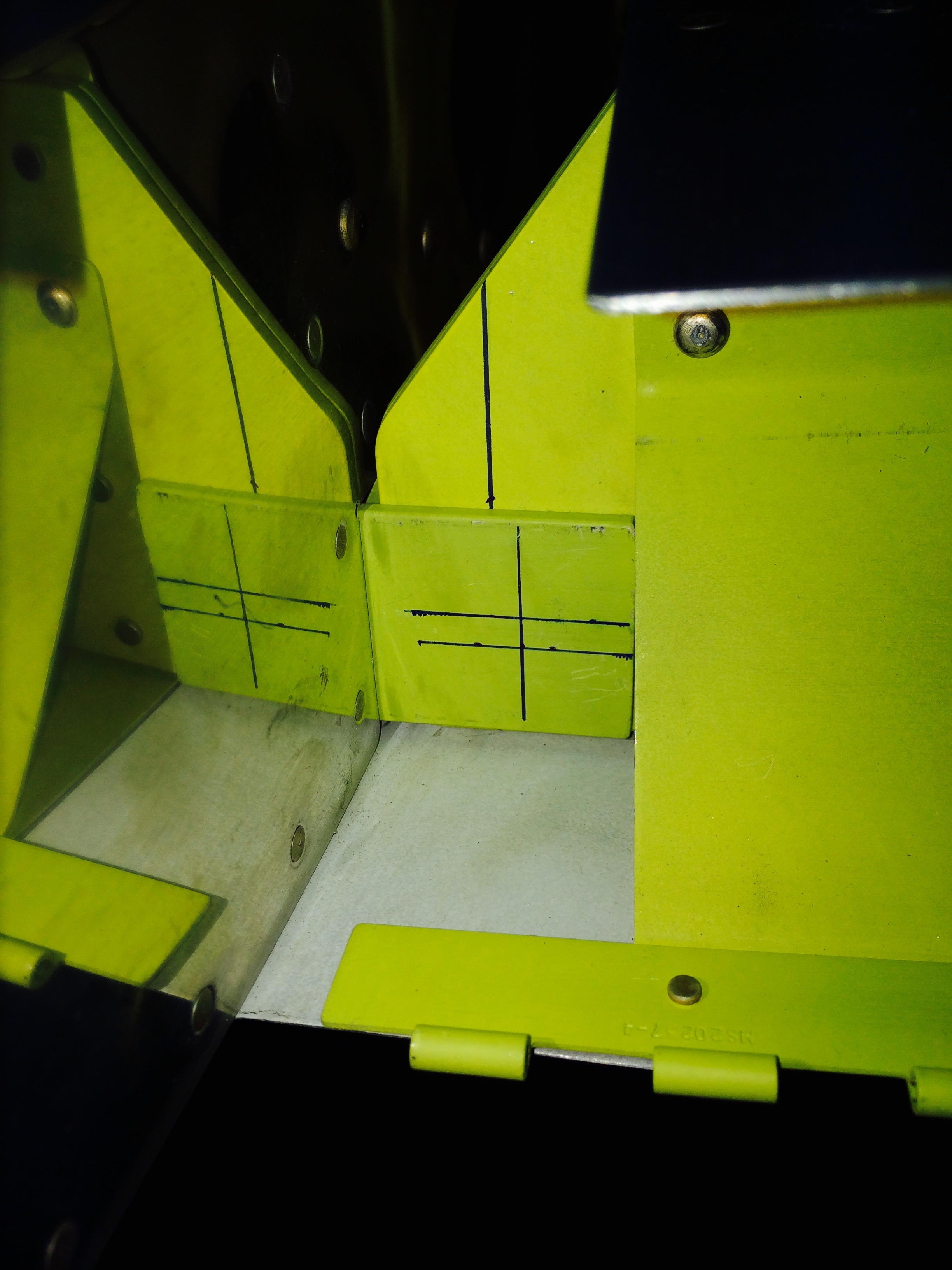
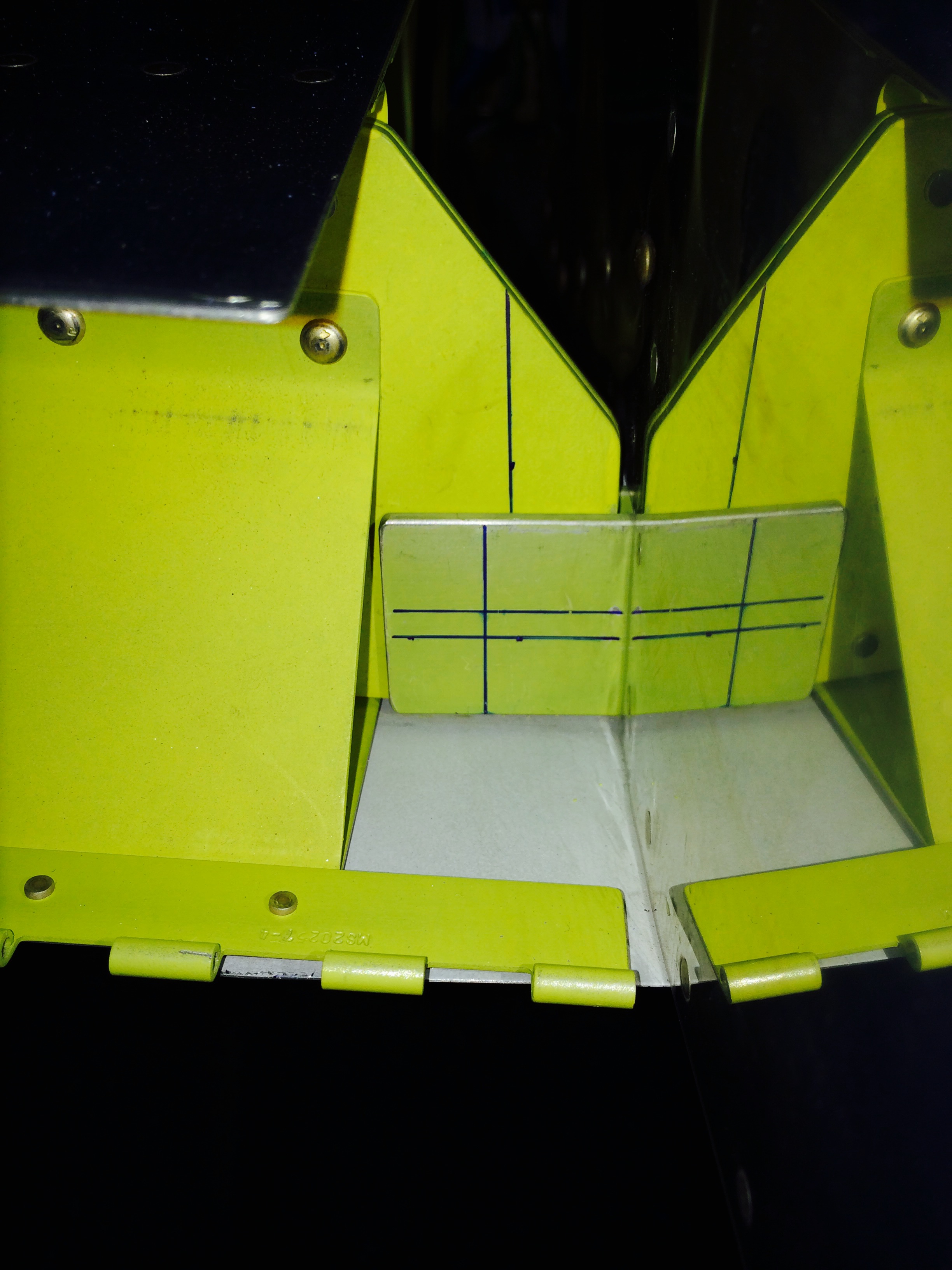
Here’s the fixture that establishes where the trailing edge of the aileron should be…it’s bolted to two tooling holes in the outboard wing rib –

And here’s a couple of pieces of wood I screwed together to hold the aileron itself in place on the fixture. You can see the two lines that define where the trailing edge should be…
 Since I already had a pretty good idea that the outboard pushrods were correctly set, I just slipped the bellcrank alignment jig into place and verified that everything was still ok.
 You can’t see the bellcrank jig very well, but it’s the silver piece of metal above the bellcrank itself. It’s placed over a pushrod bolt, and if the jig’s forward edge rests flush against the spar *and* the aileron is aligned in trail, everything is set – which it is here and in the opposite wing.
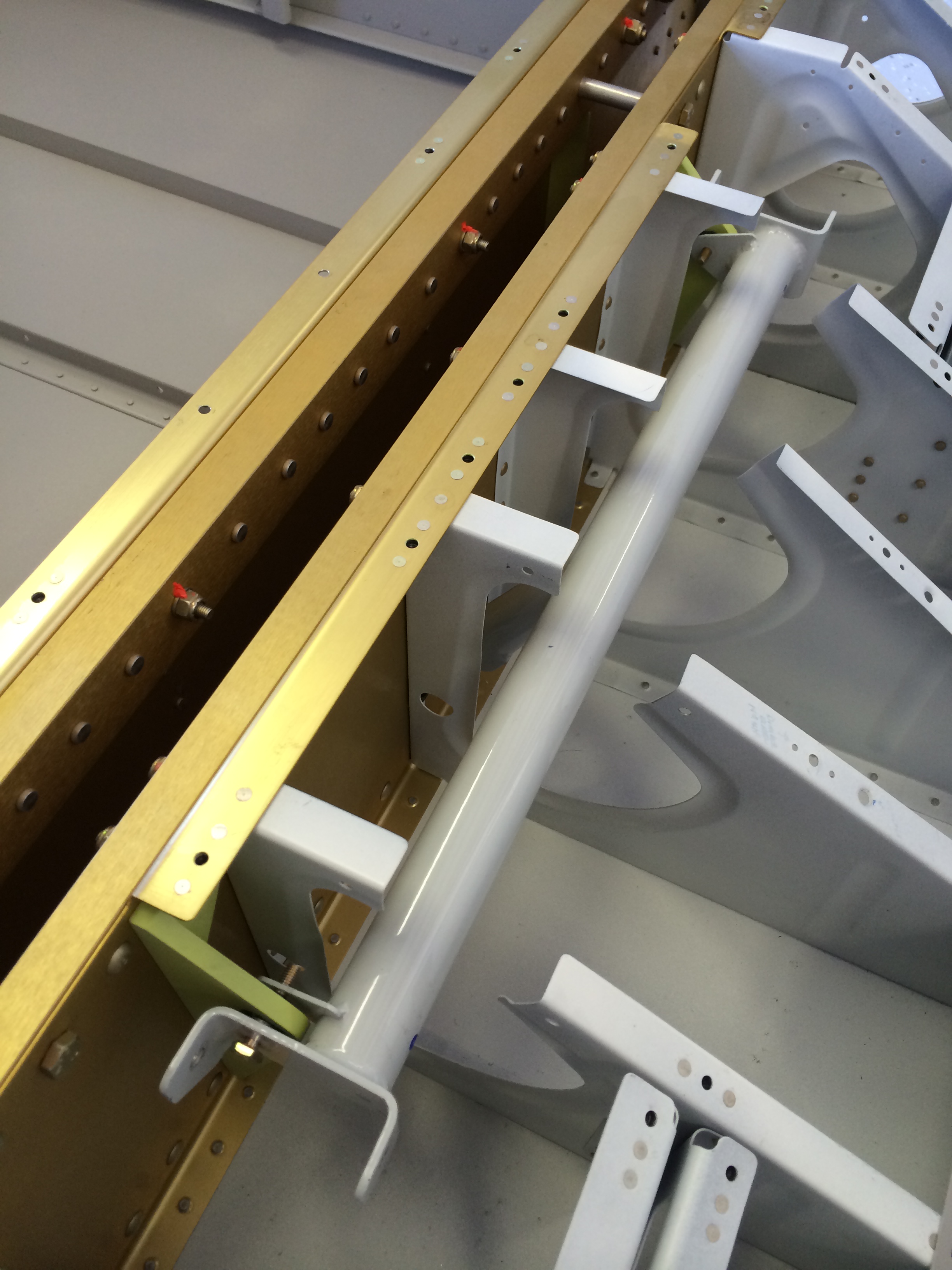
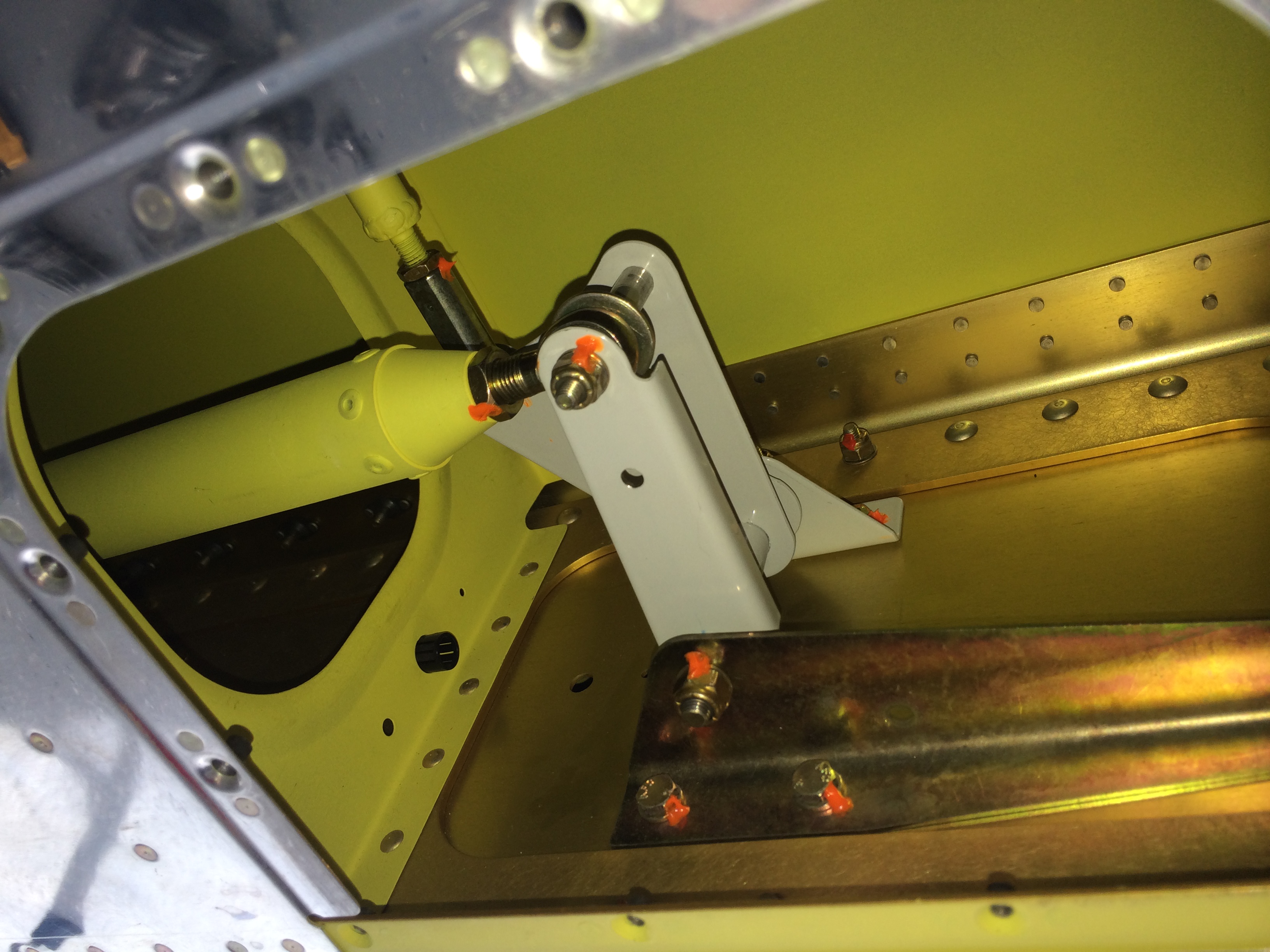 With the ailerons properly in trail, I clamped the control sticks in place so they were vertical (sorry, no pictures) and adjusted the long bellcrank-to-stick pushrods to the proper length. I then went back and torqued all the bellcrank bolts and nuts, as you can see from all the Torque-Seal in the picture.
It was kinda neat to move the control sticks and see the ailerons move…before the wings come off again I may have to throw a seat in the cockpit and play pilot for a little while!
I have a whole laundry list of things that need to be done now that the wings are fitted.
First up was fitting the wing root fairings. Nothing too difficult here…the only trick is getting the fairing to conform to the wing leading edge curve enough to get all the holes aligned with those in the wing. A little hand shaping of that area solved the hole alignment problem.
I realized that I made a small mistake several years ago when I built the wings – I match-drilled and dimpled several of the wing skin/rib holes that should have been left undrilled for the fairing attach screws. Looks like I’ll have to drill them out to the right size (#19) and then re-dimple to accept a #8 screw. No big deal.
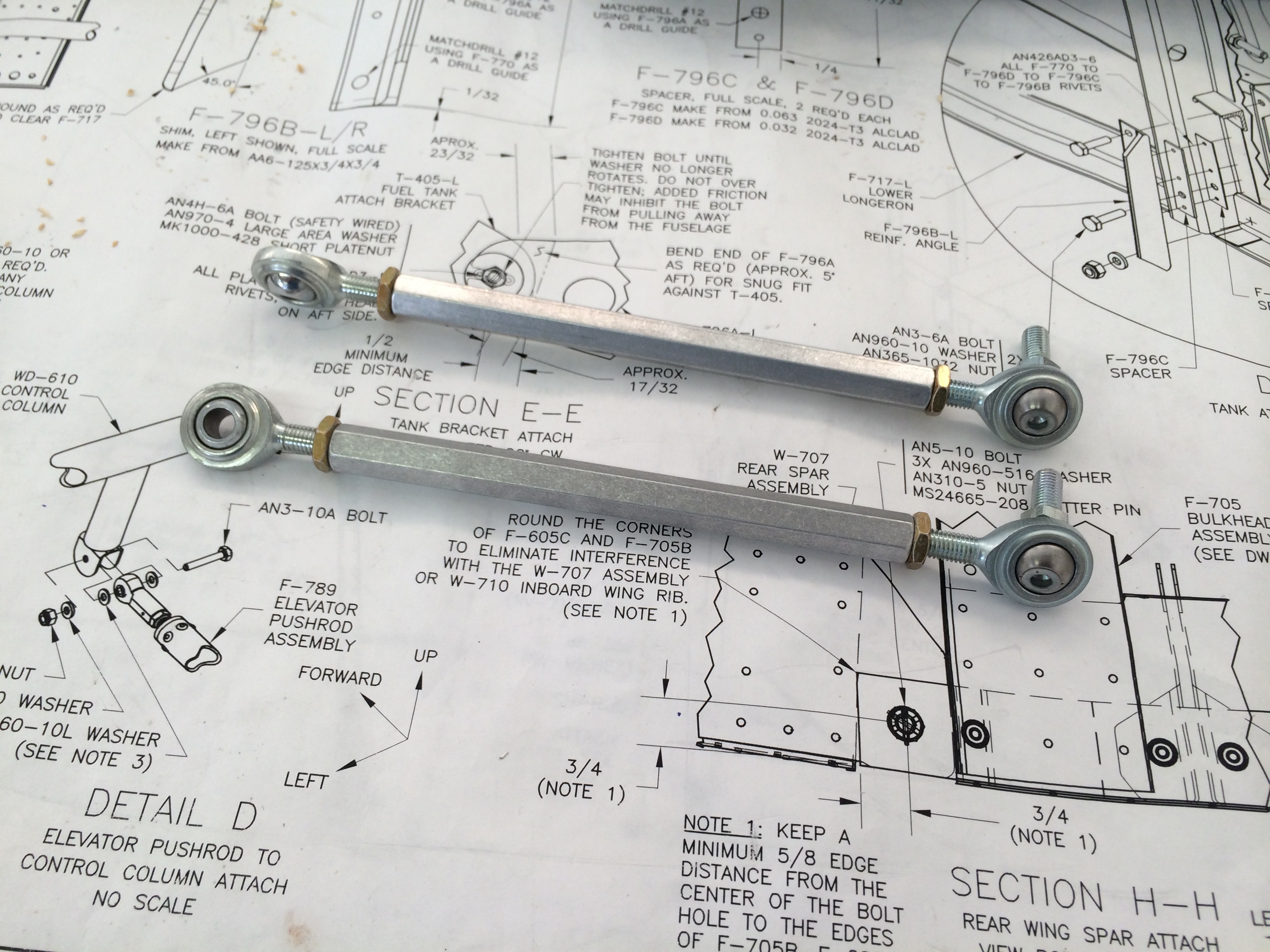 While I was at Oshkosh I bought these spiffy pre-drilled hex flap pushrods rods from Avery Tools. Drilling and tapping a piece of round tube stock for these pushrods per plans is a pain, so these Avery rods save a lot of time and effort…just screw in the rod ends, and you’re done. Cool.
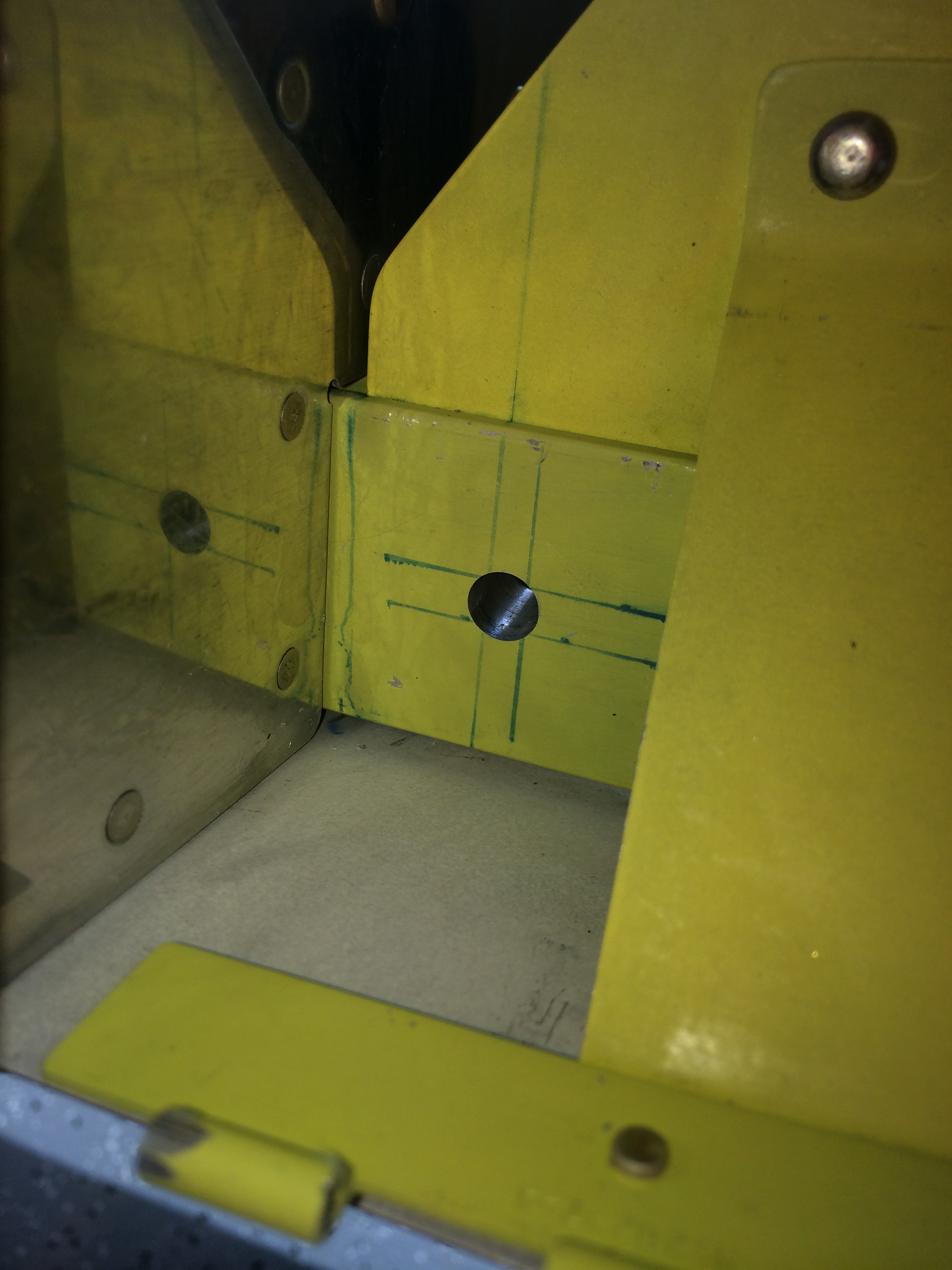
Carrying on from my previous post – there’s one task that RV builders know has to be done right the first time, and that’s drilling the holes in the aft wing spar that set wing sweep and incidence. I’ve already covered all the measurements that verify the wings are in the right position and there’s good edge distance…now it’s time to drill.
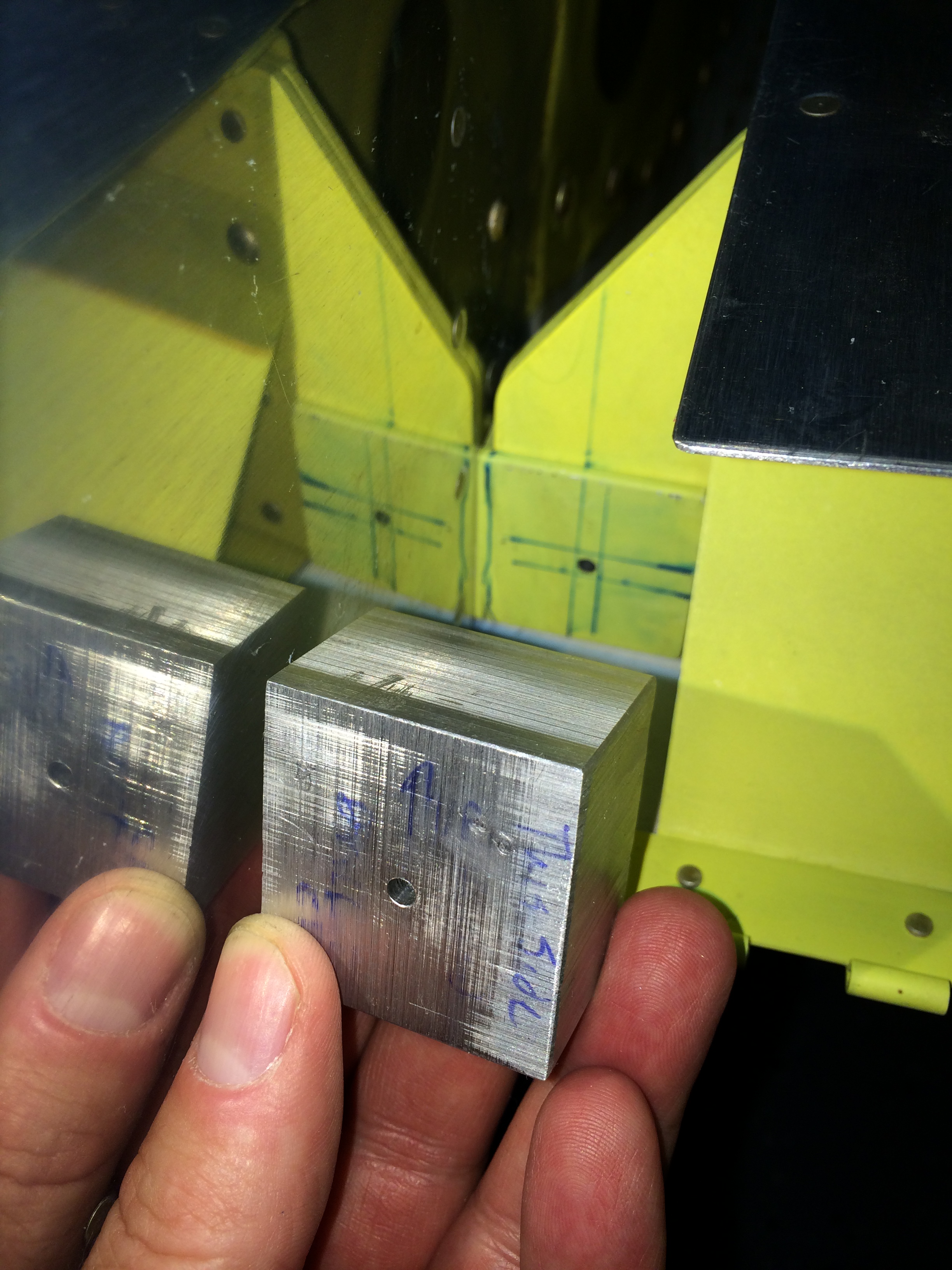
Van’s has a good description of the process on their Construction FAQ page, so I won’t repeat their words here. I found a piece of scrap aluminum bar at a local metal dealer and cut pieces to make drill blocks for #30, 3/16″ and 9/32″ drill bits and one for a 0.311″ reamer – to enlarge the hole in stages. The 9/32″ drill seems like an odd choice, but the ideal use of a reamer is on a hole that’s about 1/32″ undersize – and 9/32″ is just that for the 0.311″ reamer.
The pucker factor was pretty damn high when drilling the #30 pilot holes, but they came out fine –
I then worked up to 3/16″, 9/32″ and 0.311″ and ended up with good holes in each rear spar.
Enlarging to 3/16″ wasn’t too tough, but I was concerned about making sure the 9/32″ drill block was centered – don’t want to eat into the edge distance margin. But then I had a brainwave – insert a long 3/16″ pin punch through the 9/32″ drill block and on into the 3/16″ pilot hole, and continue until the punch’s shank hits the side of the drill block hole, centering it on the 3/16″ hole. Clamp the drill block in place, and voila – the block is centered and ready to use. Here’s the right side –
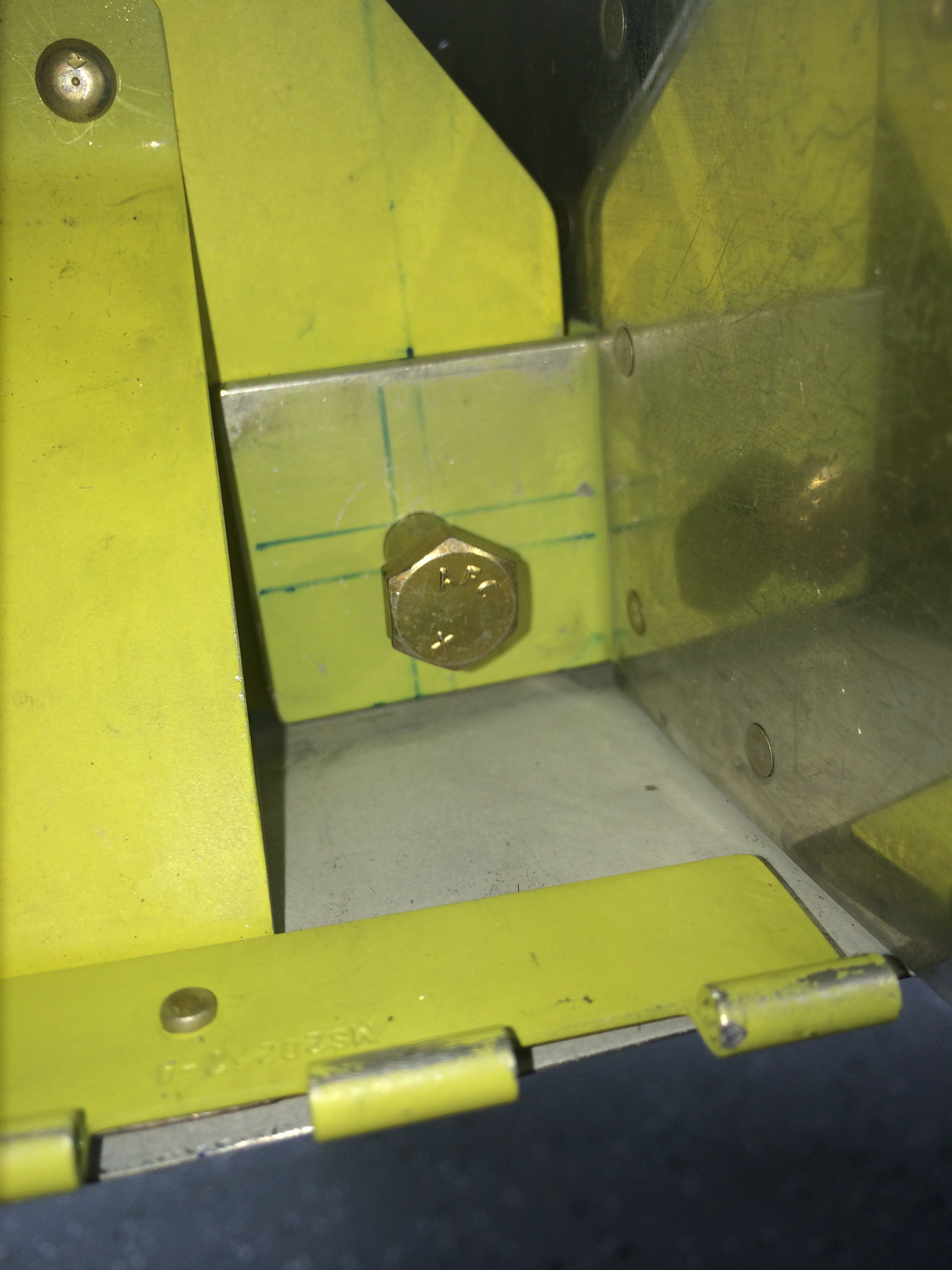 Here’s the right rear spar, without an AN5 bolt in place…
 The drill block process worked really well – finishing the holes with a 0.311″ meant a nice, snug fit for an AN5 bolt – they went in with only a little finger pressure. These bolts are supposed to be be a nominal 5/16″ diameter, but they often run undersize. Had I used a 5/16″ reamer, the bolt fit would have been ok, but probably sloppier than I’d want in this application.
So…the rear spars are drilled and it’s a huge relief. I have a backlog of things that need to be done to the wings, like rigging the ailerons and flaps, and it’s time to make some serious forward progress.
Food can be effective bribe. Last weekend I bribed Ellen and Whitney, and RV-7 friends Andy Olech and Allison Bailey, with lunch at the Midfield Cafe to help install the wings for the first time. Thanks Andy and Allison, we appreciate you flying up from Hartford and spending the day with us!
And as always, thanks to my family – Ellen and Whits, I couldn’t do any of this without you !
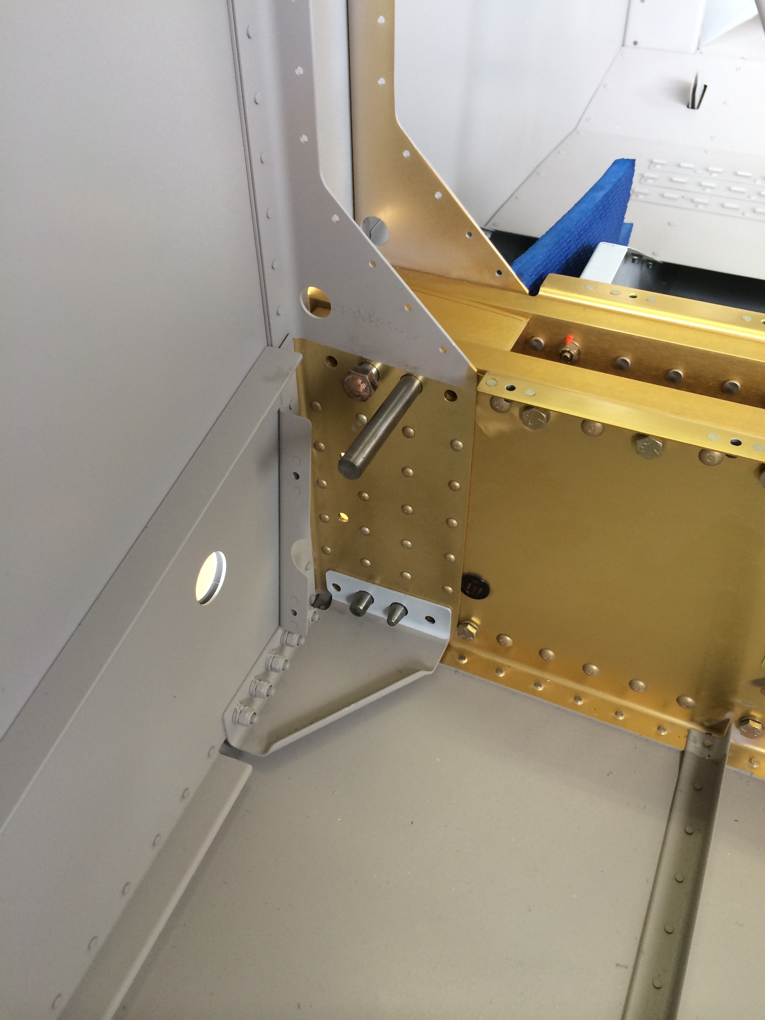
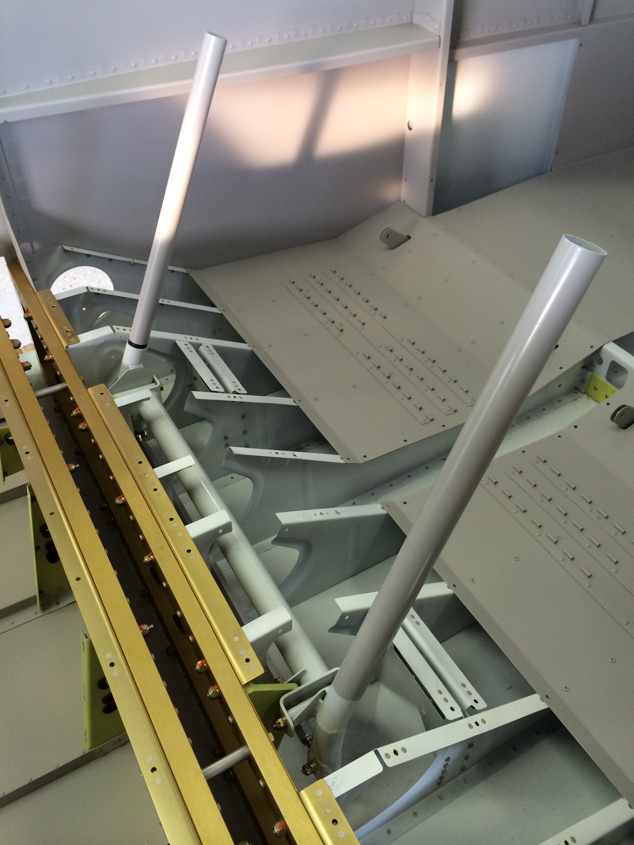
 This is one of those times in the project when a lot of past effort to maintain tight tolerances really pays off. Every RV slow-builder stresses about making sure the front and rear spar bulkhead halves in the fuselage are spaced 1.438″ apart as required by the plans. With the help of a little Boelube, the spar ends slid right into the fuselage. Cool.
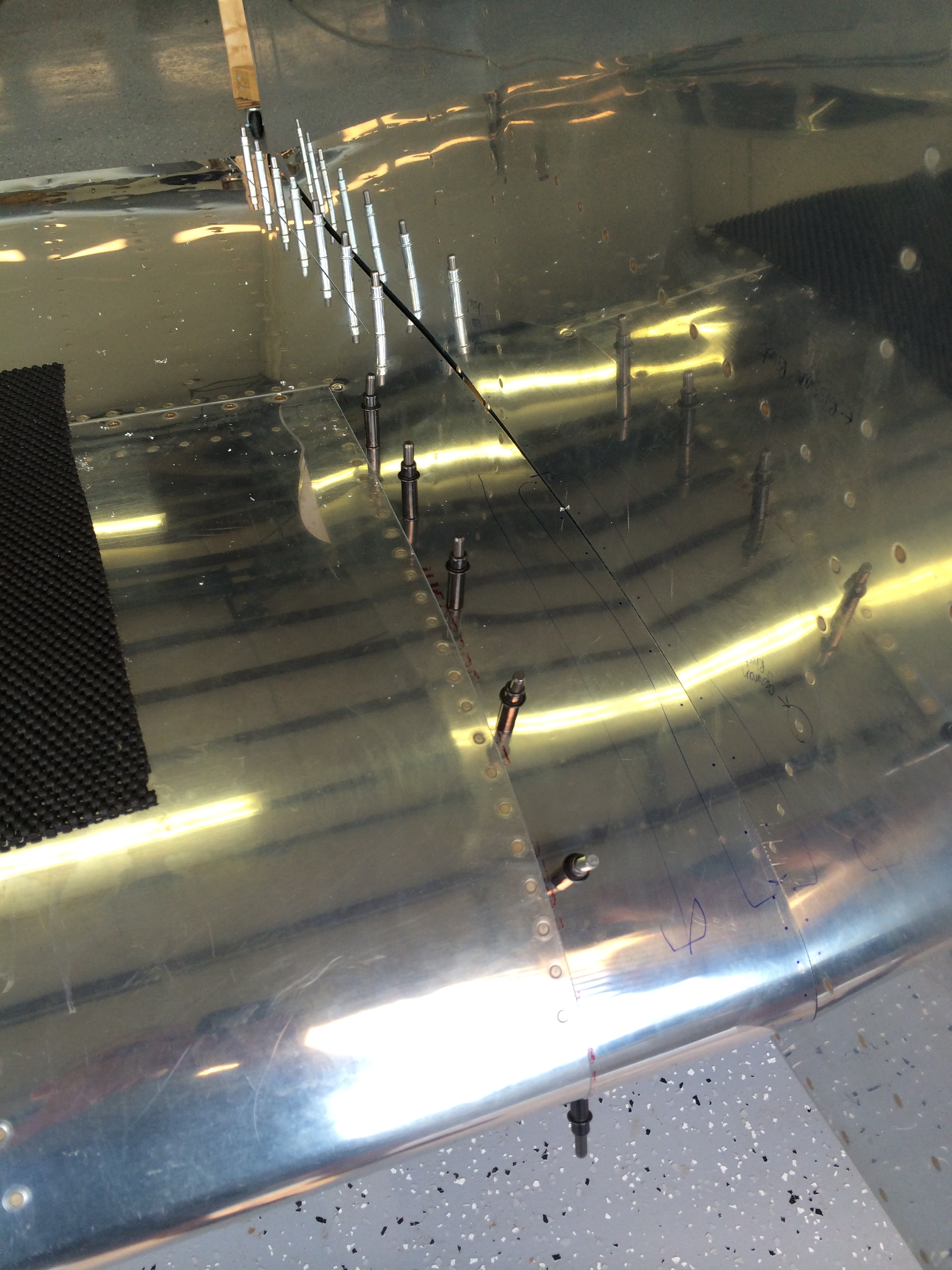
With Andy, Allison, Ellen and Whitney adjusting wing position, I inserted a couple of taper pins into bolt holes for each wing. Van’s calls for four pins, so before I made any final measurements and drilled any holes, I borrowed some long, custom-made stainless steel taper pins to augment the four pins I made from hardware-store bolts.
Thanks to Rich Mileika for making those really nice stainless steel taper pins, to John Sannizzaro and Bill Higgins for flying up to Nashua yesterday and helping me get the last 3-4 taper pins in so that the wings are secure, and last but certainly not least, thanks to Bob Weldon and his daughter Emma for muscle power and precision plumb bob stabilization <g>.
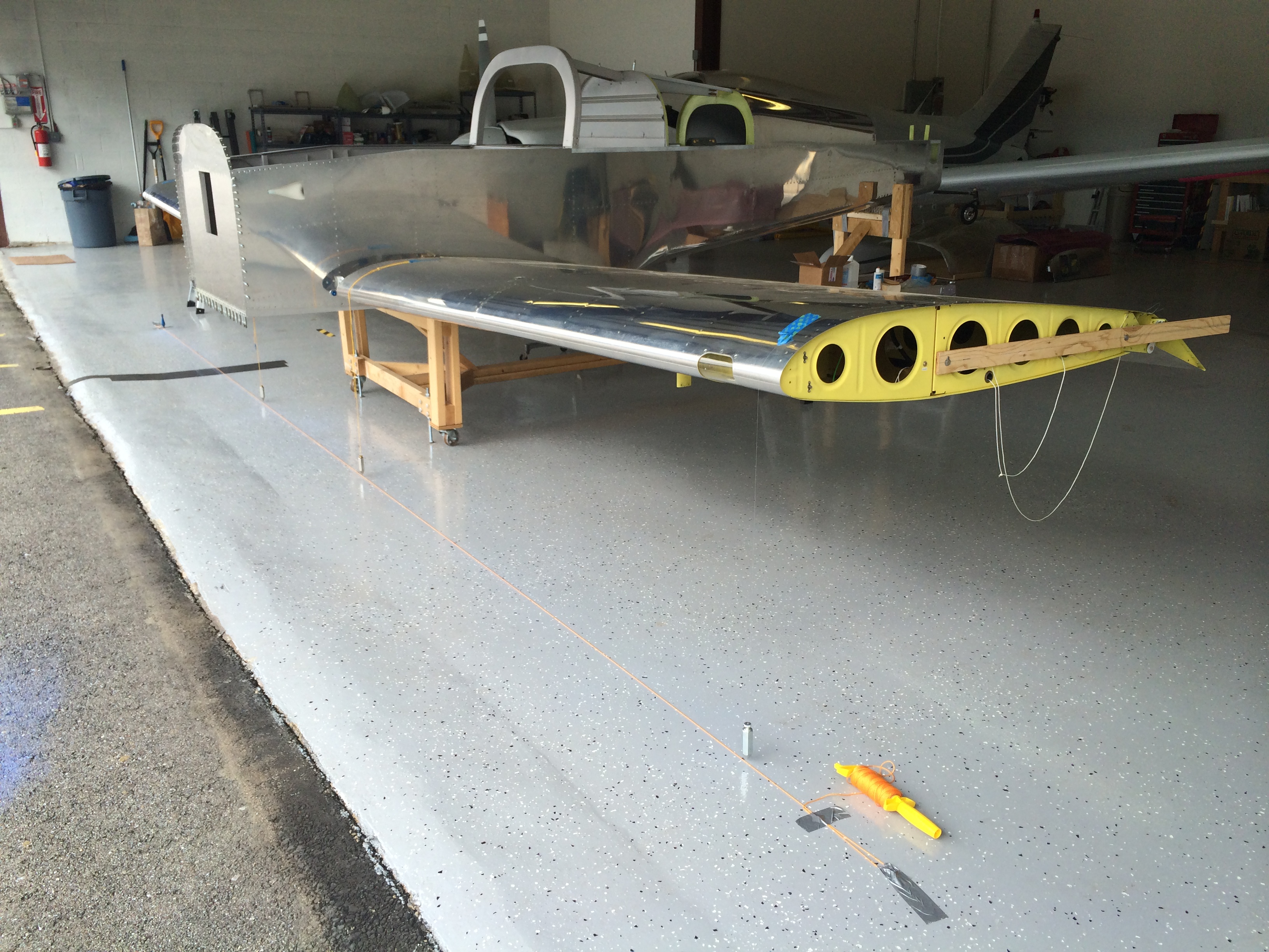
With the wings temporarily installed, I made sure the fuselage was level laterally and longitudinally. The plans call for measuring longitudinal level on the longerons at the cockpit, but these almost always have some residual twist from the bending process that makes it hard to get a good level measurement.
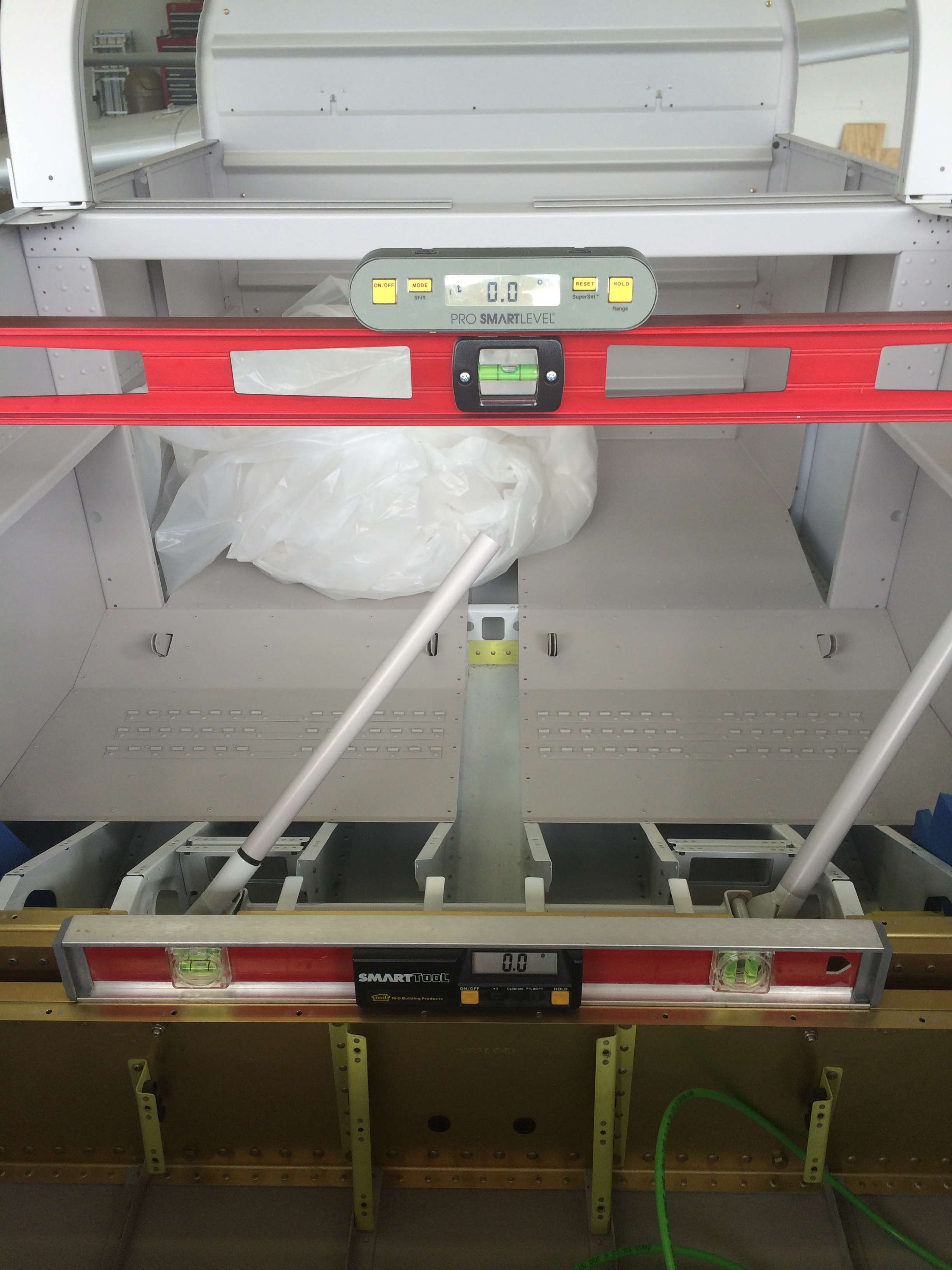 So, I just moved the levels back a few feet to a straight portion of the longerons. I had to adjust the cradle a little to get everything spot on, no big deal.
According to the Van’s FAQ on wing incidence and sweep, the next measurement is from reference points on each wingtip to a common point on the aft fuselage. My measurements were the same to within 1/32″…cool again.
I then dropped plumb bobs from the wing leading edges – one inboard and one outboard on each wing panel, and laid out a reference line between the outboard plumb bobs to serve as a reference for double-checking sweep. Measuring the distance from the inboard plumb bobs to the reference line, I found that each wing had only 7/32″ of sweep, well within the 1/2″ tolerance that Van’s suggests.
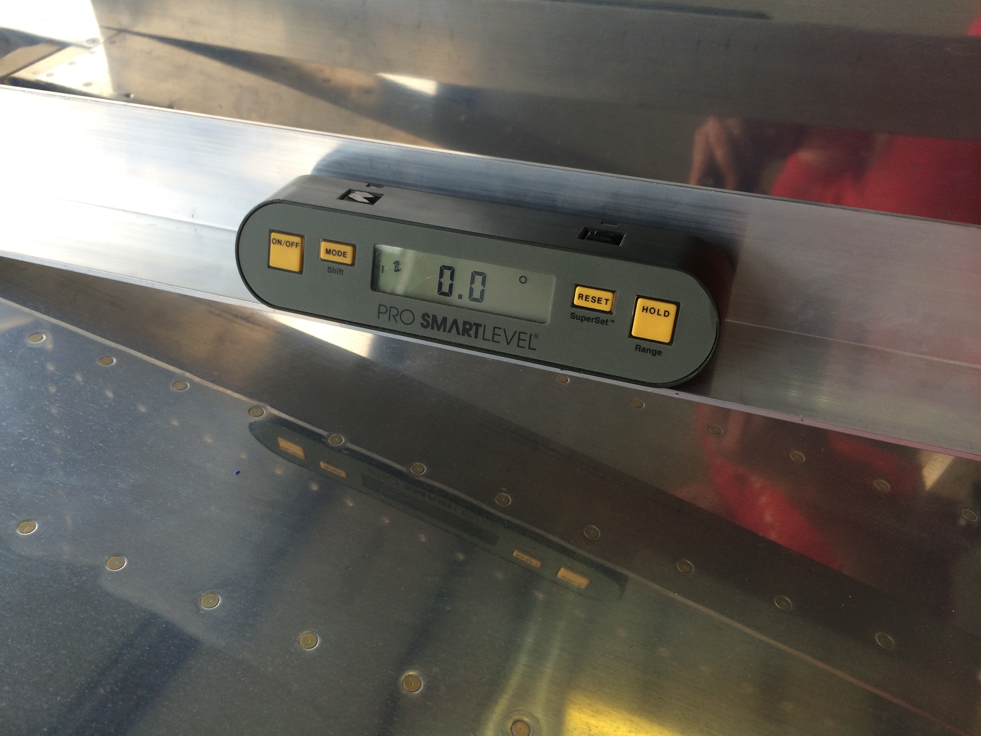
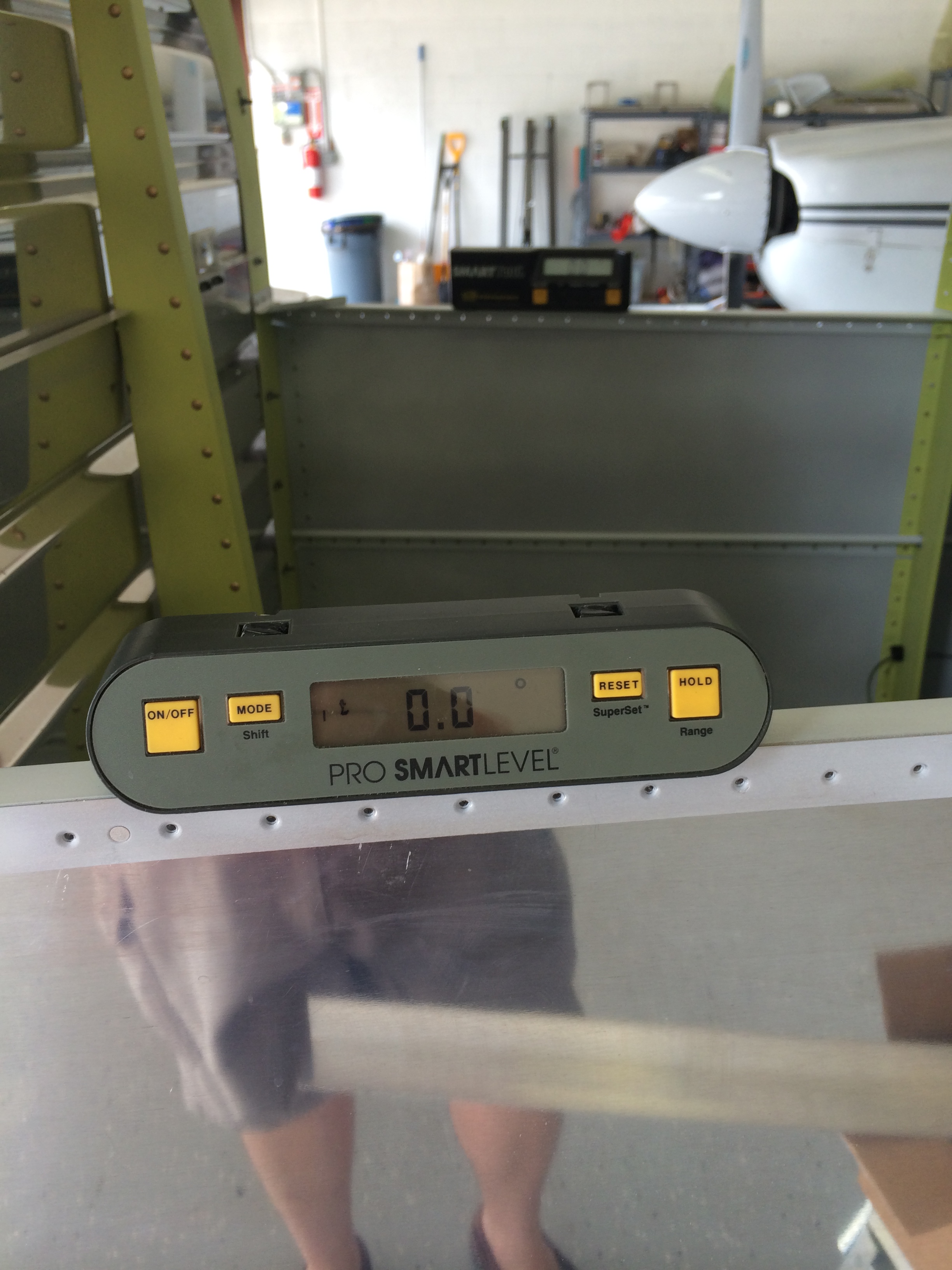
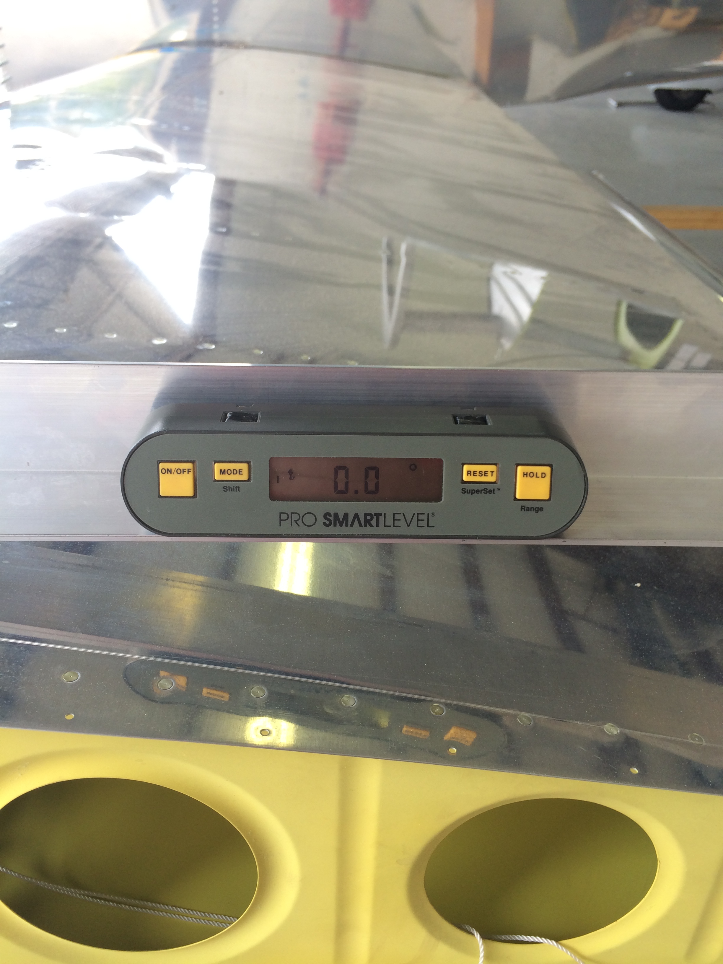
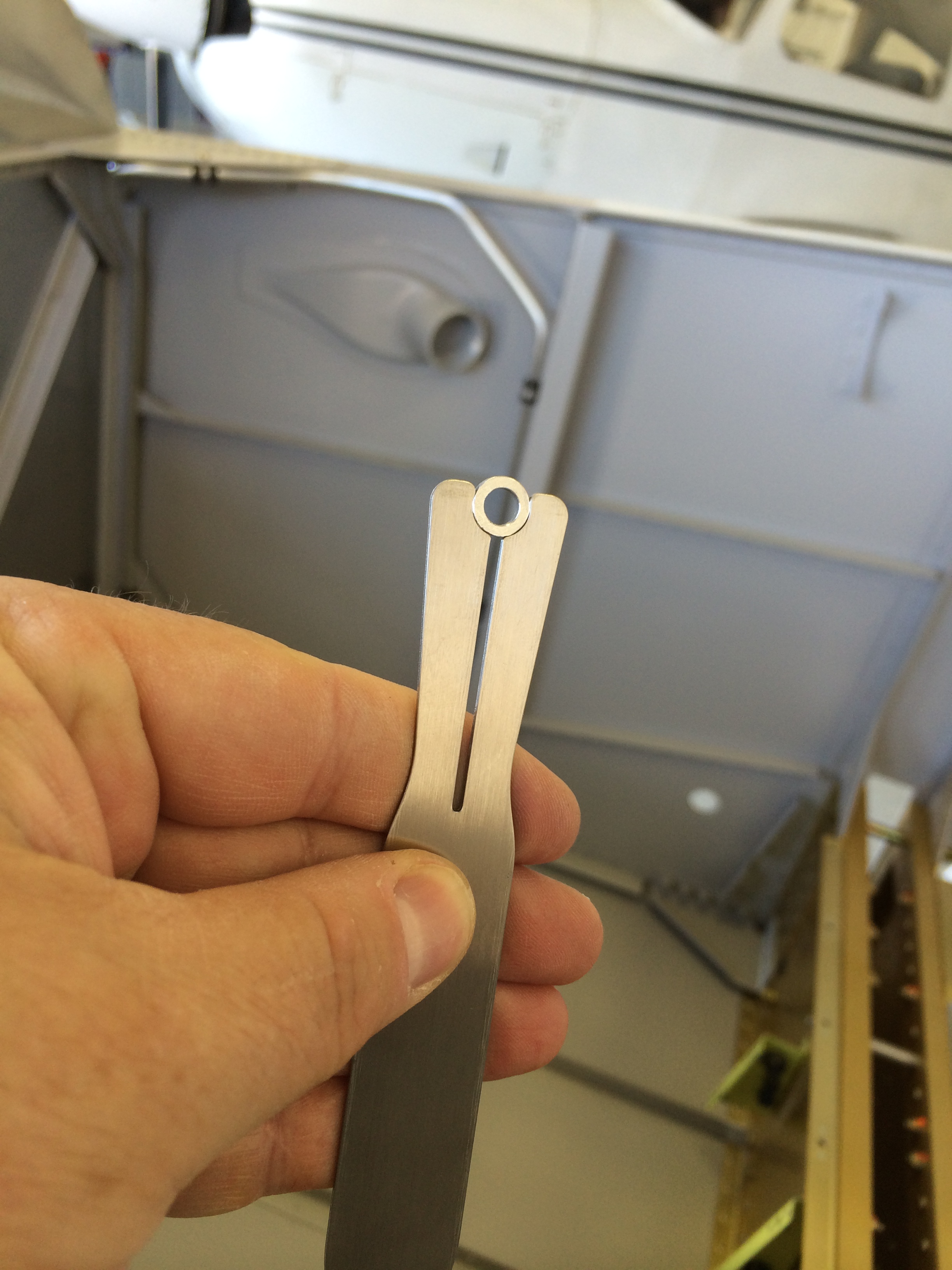
The next measurements check wing angle of incidence. This requires making a simple tool – a carpenter’s level or metal channel with a 3″ spacer on one end. The flat end is placed on the wing skin above the main spar web, and the spacer sits on the skin above the aft spar web. When a level placed on the tool reads zero, the wing has a 1 degree angle of incidence.
The pic above shows the left wing incidence is right on the money. The right wing was the same.
Just for a goof, I checked the angle of incidence at each wingtip…every measurement was within 0.1 degree. This is a real tribute to the quality of Van’s prepunched kits; with reasonable effort, it’s possible to build a nice, straight airplane.
I also test-fitted the flaps to make sure the inboard flap skins fit nicely against the fuselage…

…and it looks like they do.
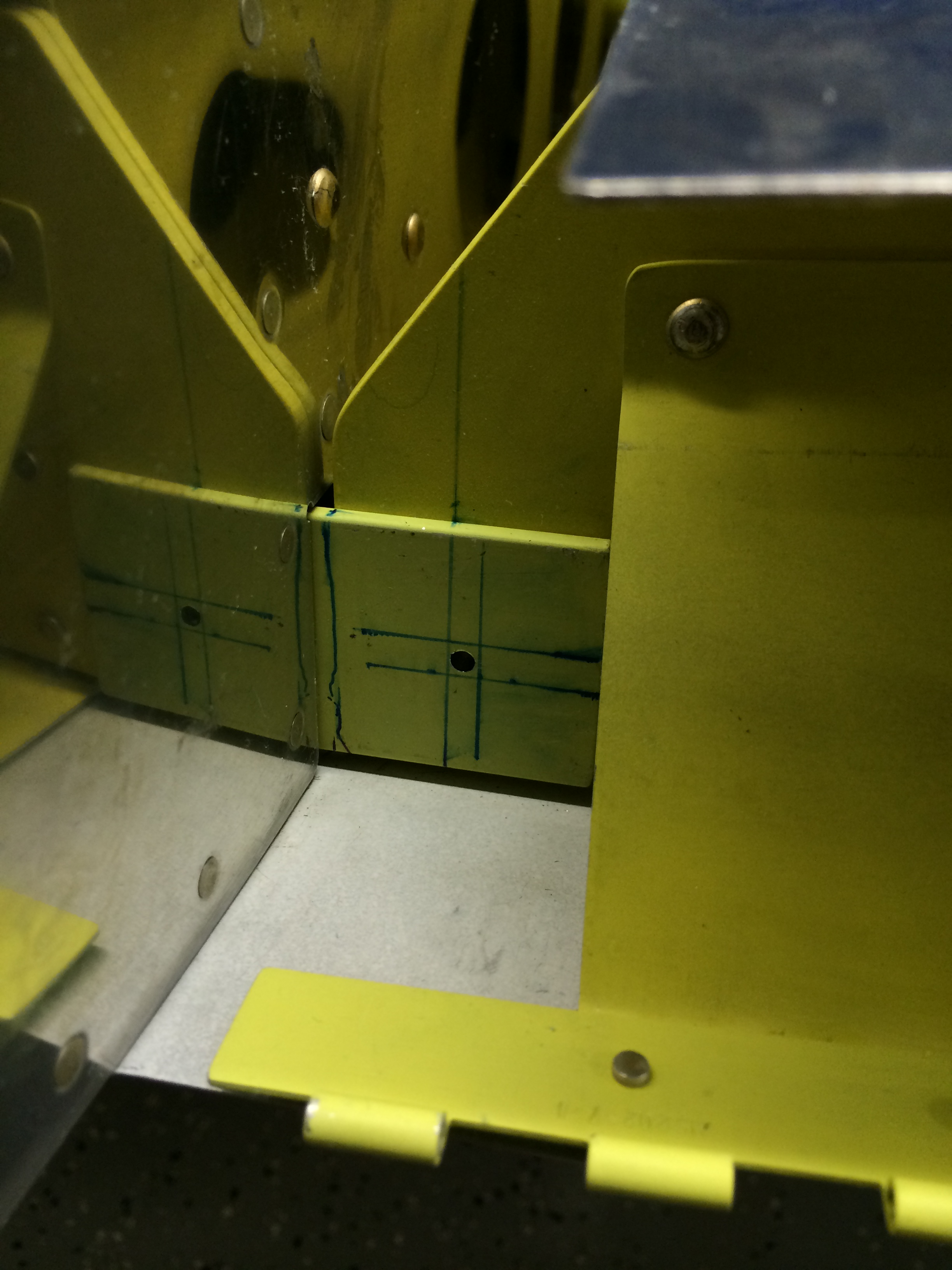
The last and most critical measurements are edge distance on the rear spar for the hole that accommodates a single attach bolt. I laid out lines on the fuselage and wing spar attachments that represent minimum edge distance from the hole center. As long as there’s distance between the vertical line on the wing spar fitting and the vertical line on the fuselage fitting, there’s sufficient edge distance for a 5/16″ bolt hole.
The right wing looks good…
…and so does the left wing.
I’m not in a rush to drill these holes. They’re one of the few gotta-do-it-right-the-first-time things on the project, and I plan to sneak up on them one step at a time.
More to follow…
With the the shop rearranged, there are a few prep things that need to be done before the wings can be fitted. First up is reinstalling the control stick mount assembly so the aileron pushrods can attached and rigged. The assembly was initially drilled to the F-704 bulkhead way back when I started the fuse a few years ago.
There are a lot of bolts and spacers that must be assembled in order so that there’s no sideload on the bearings when the bolts are tightened.
There are a couple of small washers that go on either side of the bolts that attach the control sticks, aileron pushrods and a connecting rod that makes sure the sticks move together.
These washers are a pain to maneuver without help, so I broke out the Avery washer wrenches…they did the trick.
The very last bolts to be installed were the ones that that hold the sticks to the mounts and allow them to move laterally. Because this is a rotating joint, normal Nylok self-locking nuts can’t be used – the castle nuts only get torqued enough to allow a cotter pin to be installed. I won’t do that until I’m ready to permanently install the control sticks.
On the other hand, they look so good that I might just leave them in!
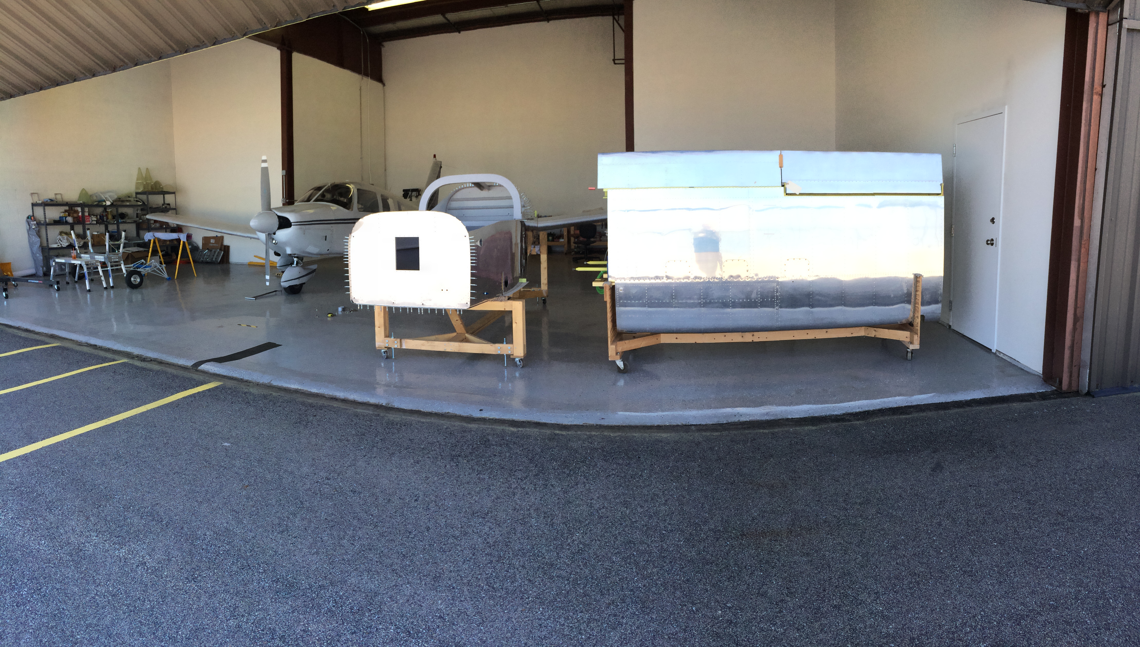
My hangar mates won’t be flying the Archer for awhile, so we’re taking the opportunity to rearrange the hangar in preparation for fitting the wings. The fuselage gets moved to the front, so there’s plenty of work space.
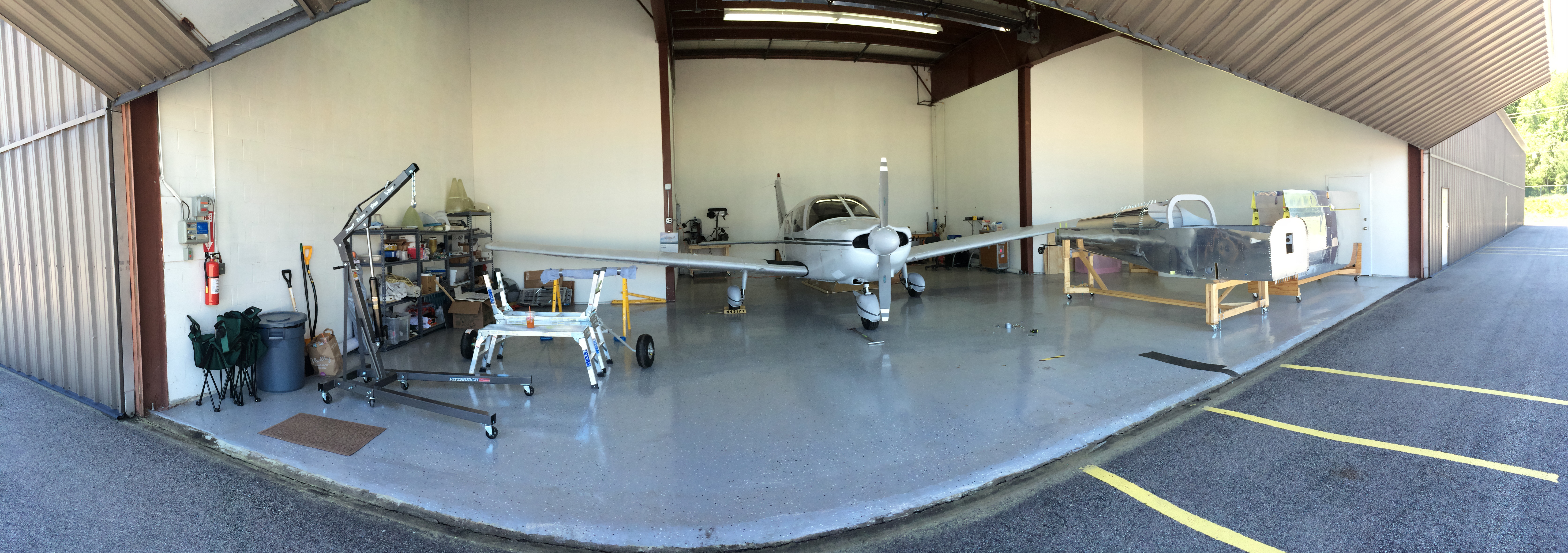
I did some cipherin’ on my cheapo CAD program and the drawings say we should have enough space to get the wings on and still be able to do work around the fuse.
 And now it’s back to fun with moving. Only two weeks to go ’til closing…
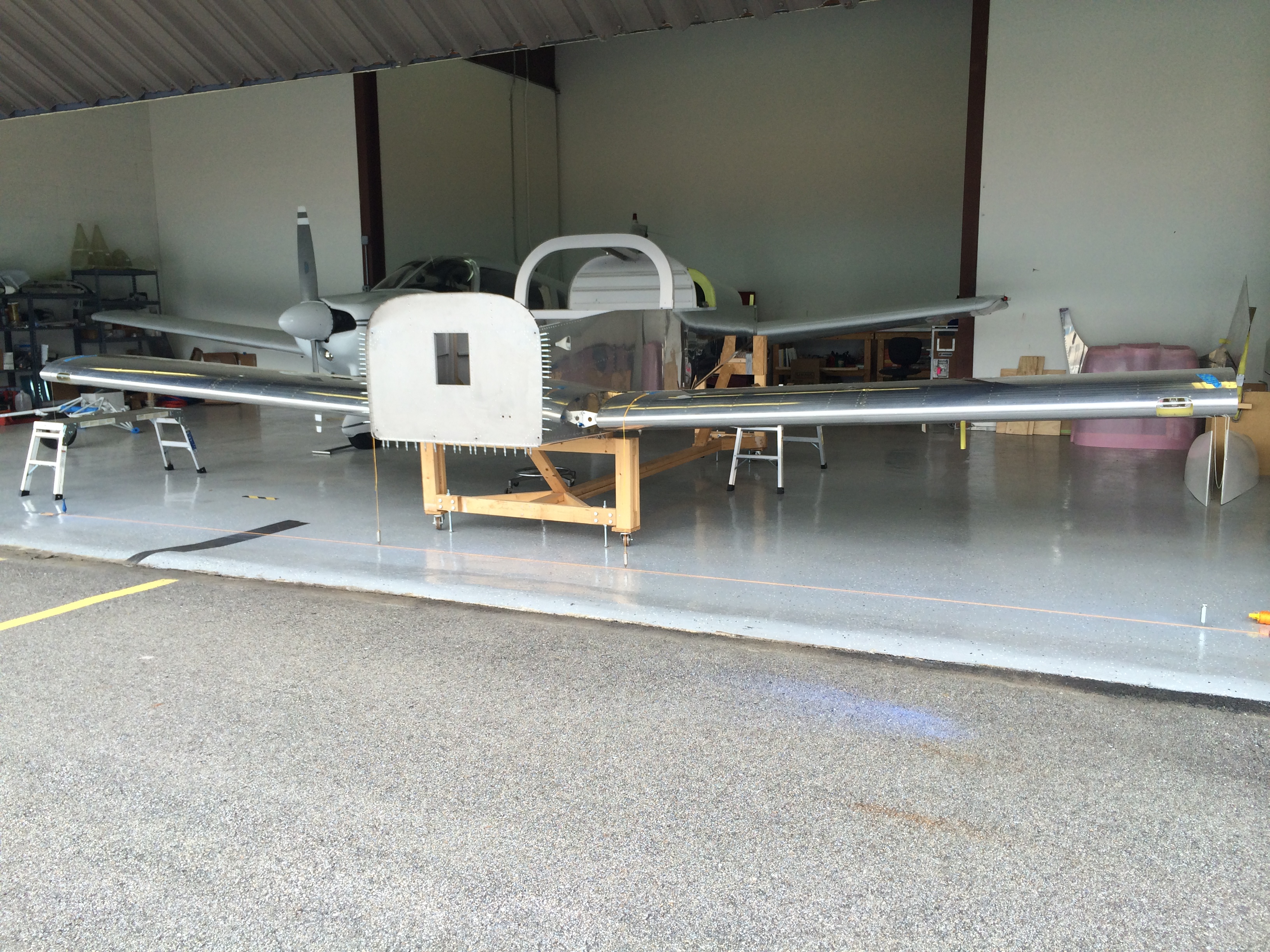
We’re building in a large (by Boston standards) one-car garage, so we had to move the wings out to make room for the fuselage. Today was the day we rented a large U-Haul truck to make the move to our storage space (and eventual building location) at Hanscom Field (KBED). I’d already moved the empennage out there earlier this year, so bit by bit the airplane is making its way to the airport. Ellen is holding the cradle in place while I take one last picture of the wings at the house.

Ellen and the wings
The wings in the truck. That cradle is pretty solid, but we didn’t want anything shifting around during the 11-mile drive to the airport. So everything is tied and chocked securely.

Wings securely mounted in the U-Haul truck
The trip was a non-event, and we got the wings safely to the hangar. Cool!

Wings safely at the Aero Club
The shop is empty, but not for long. After a little cleanup and rearranging, I’ll continue on with the fuselage.
Empty shop, but not for long!