Wiring and plumbing the wings

We’re getting close to Oshkosh and I wanted to get as much done as I could before our trip, so over the weekend I installed the pitot tube and wired landing lights, OAT probe and pitot heat to their circuits in the fuselage.

Here are the Baja Designs Squadron Pro landing lights connected and doing their thing. Not terribly bright in this picture but they hurt to look at, and that’s a good thing…

Landing lights

No post on landing light installation would be complete without proof that the GAD-27 can indeed flash the lights…

I had fitted and plumbed the pitot tube several years ago so installation was relatively straightforward – just had to connect the AN plumbing and heater connector, then screw it to the pitot mast. And yes indeed, it gets hot…

Heatet pitot is hot!I screwed up the fuel tank feed lines, so some surgery was required to install an AN union and line to the left fuel tank. Once that was done, I reinstalled the vent line I fabricated a few years back. The RG-316 coax you see snaking out from the rubber gasket is a line that connects a Princeton capacitive fuel level sender to the fuel tank’s BNC connector.

Left fuel tank plumbed

Same thing on the right wing…

Right fuel tank plumbedPlumbed the right wing as well, and installed the fuel tank support bolts on both sides.

Pitot-static and OAT connected

Connected the OAT probe and pitot-static lines in the cockpit.

More right wing plumbing…and finished connecting the right fuel tank. Had to do another splice job on the fuel line, but it came out fine.

And now we’re off to Oshkosh!

On the wing

Now that I’m done with transition training, I’m all fired up to finish the Mighty RV. So..let’s get those wings on!

Starting the wing install
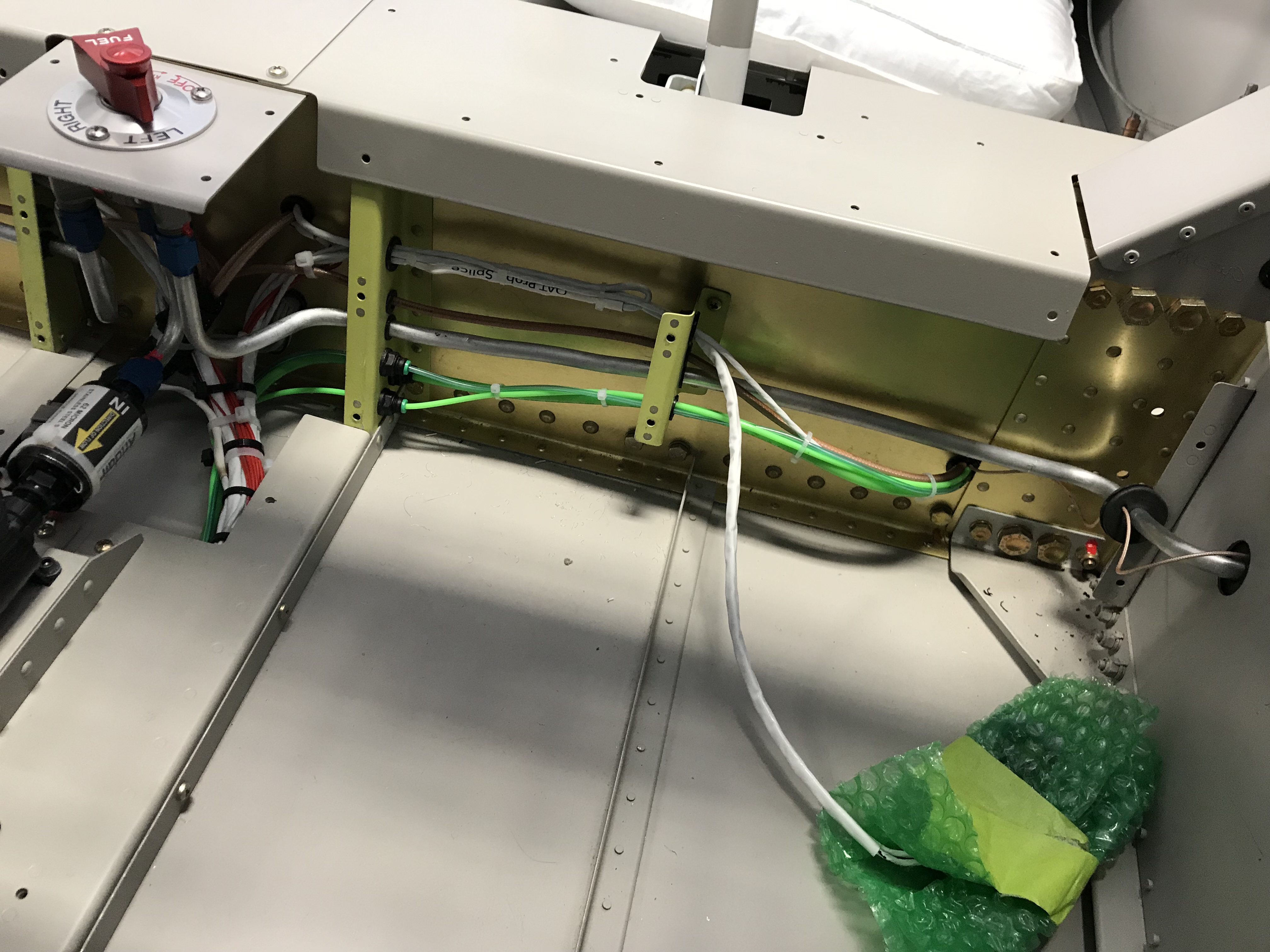
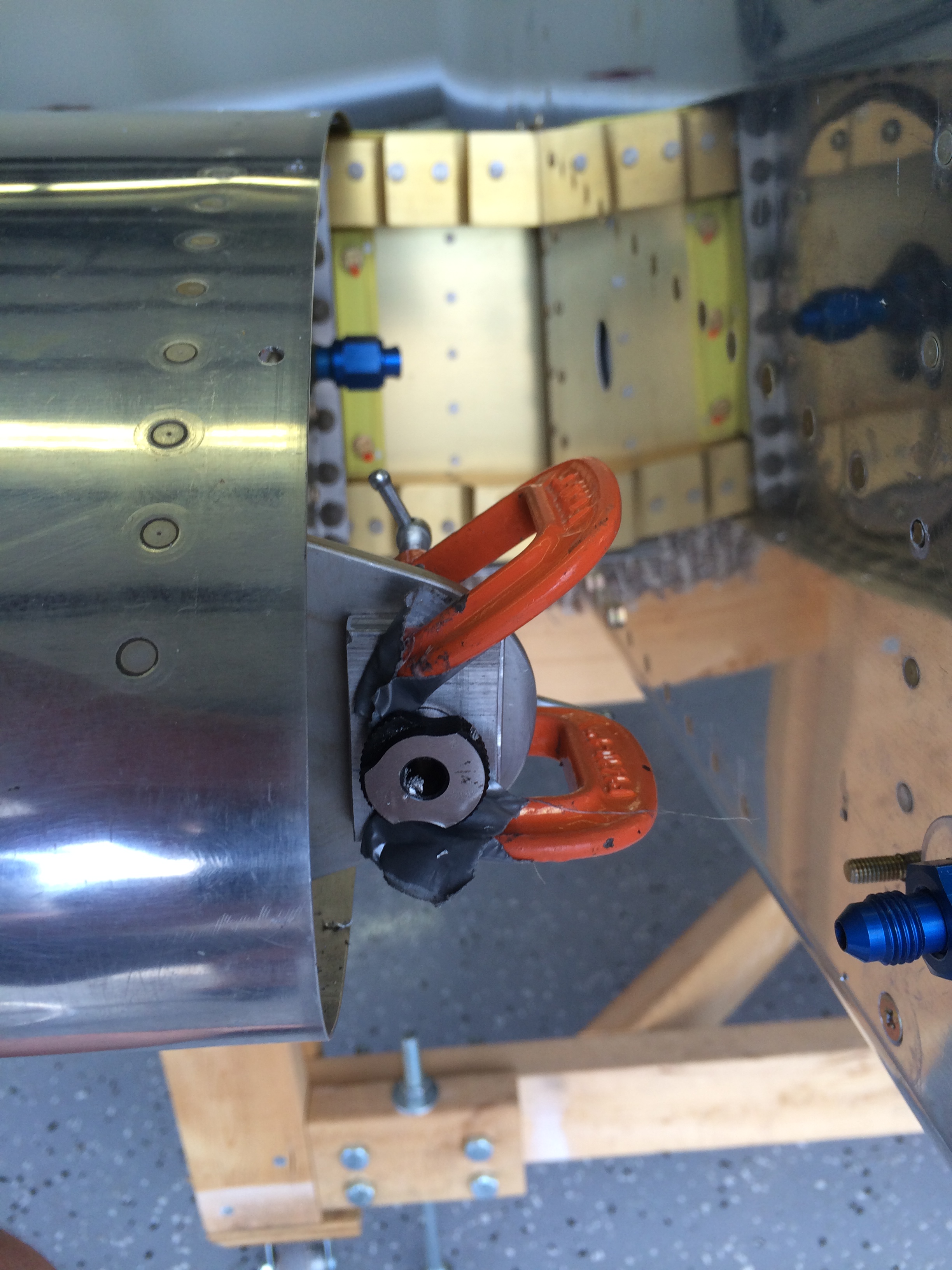
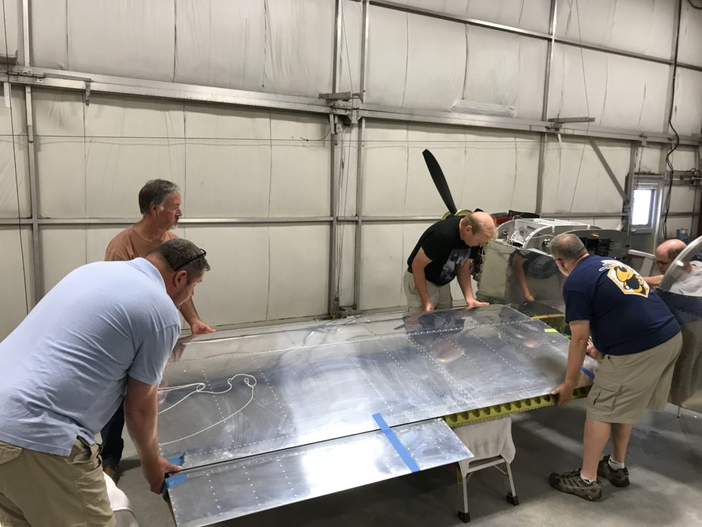
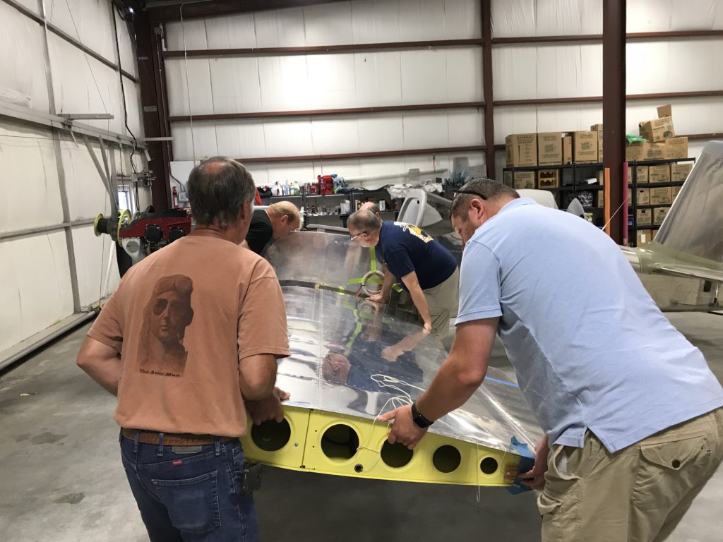
The promise of beer and burgers made it easy to co-opt some of my flying and/or RV-buidling friends to come over to the ThermosWorks on Saturday. The wings aren’t particularly heavy, but a few extra pairs of hands come in handy when trying to maneuver the wing spar into it’s slot in the fuselage.

Another wing install

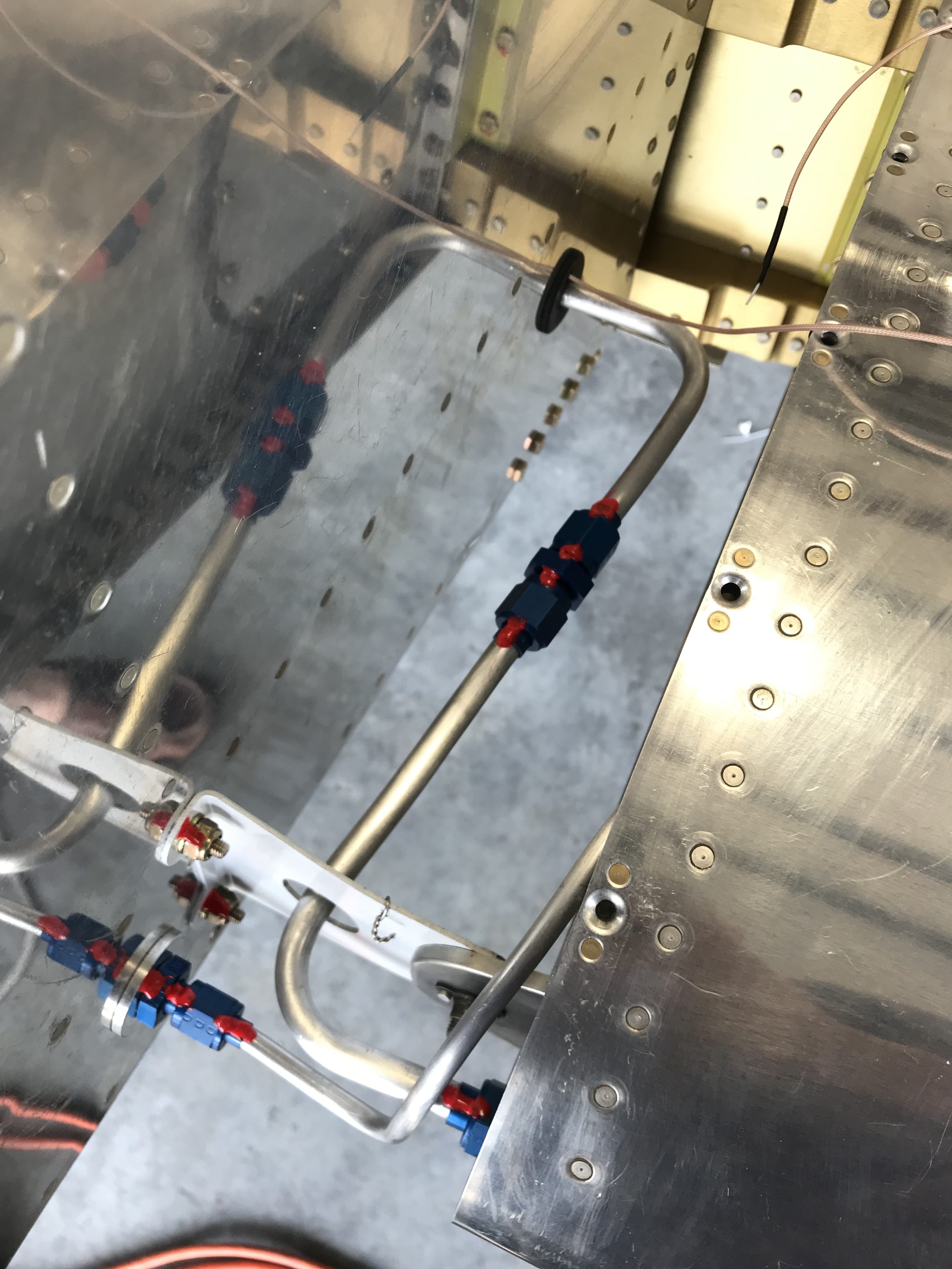
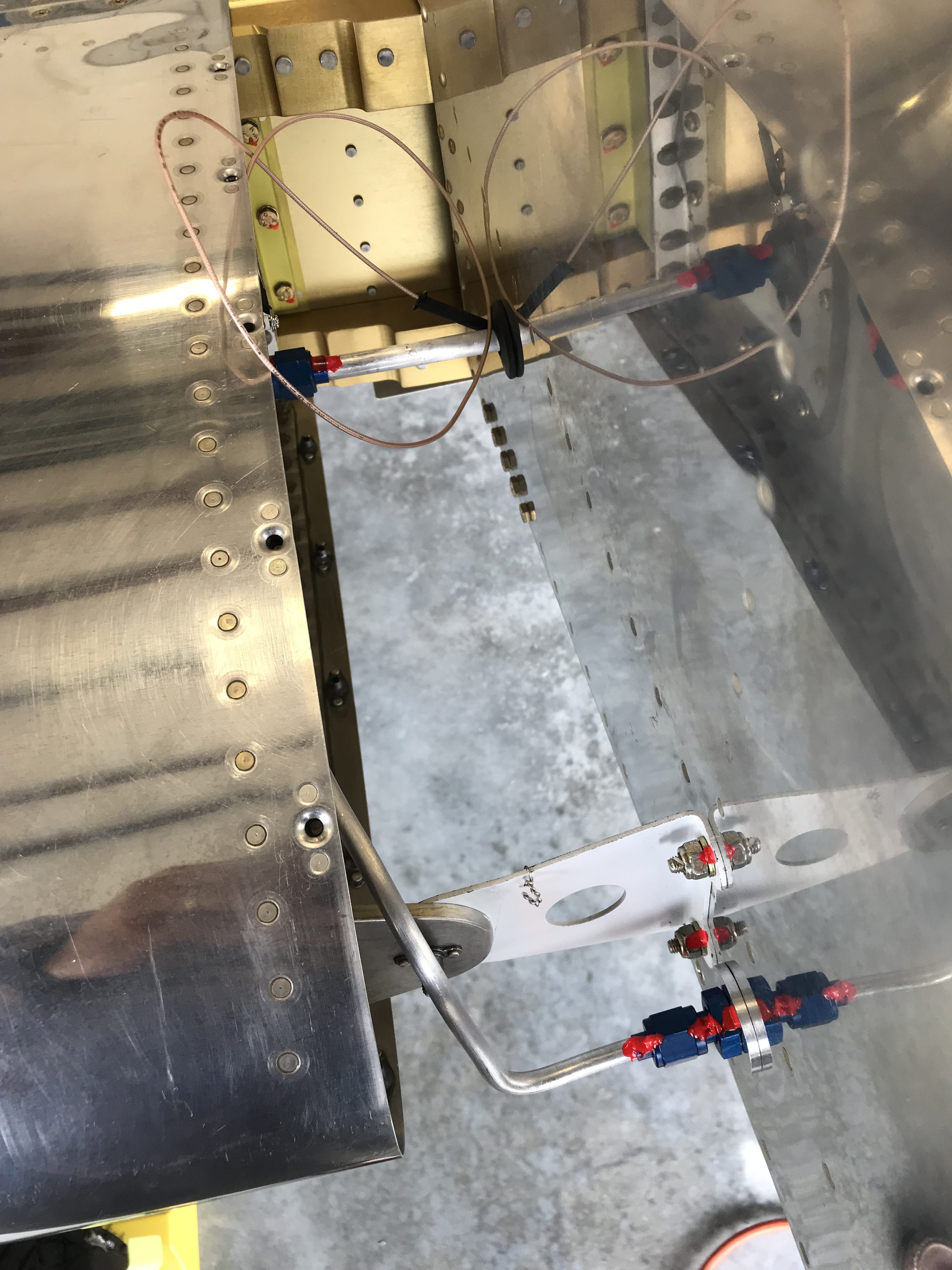
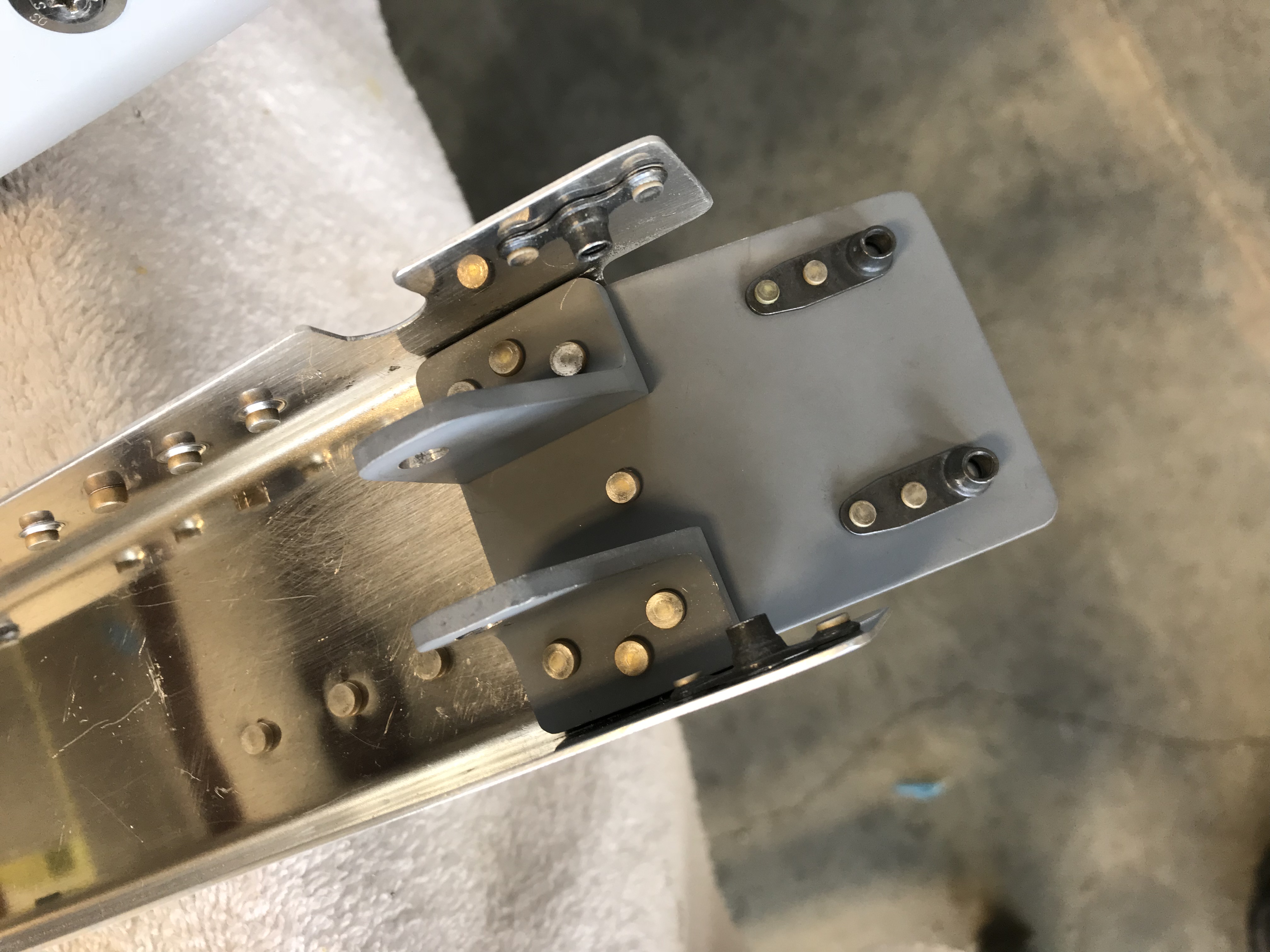
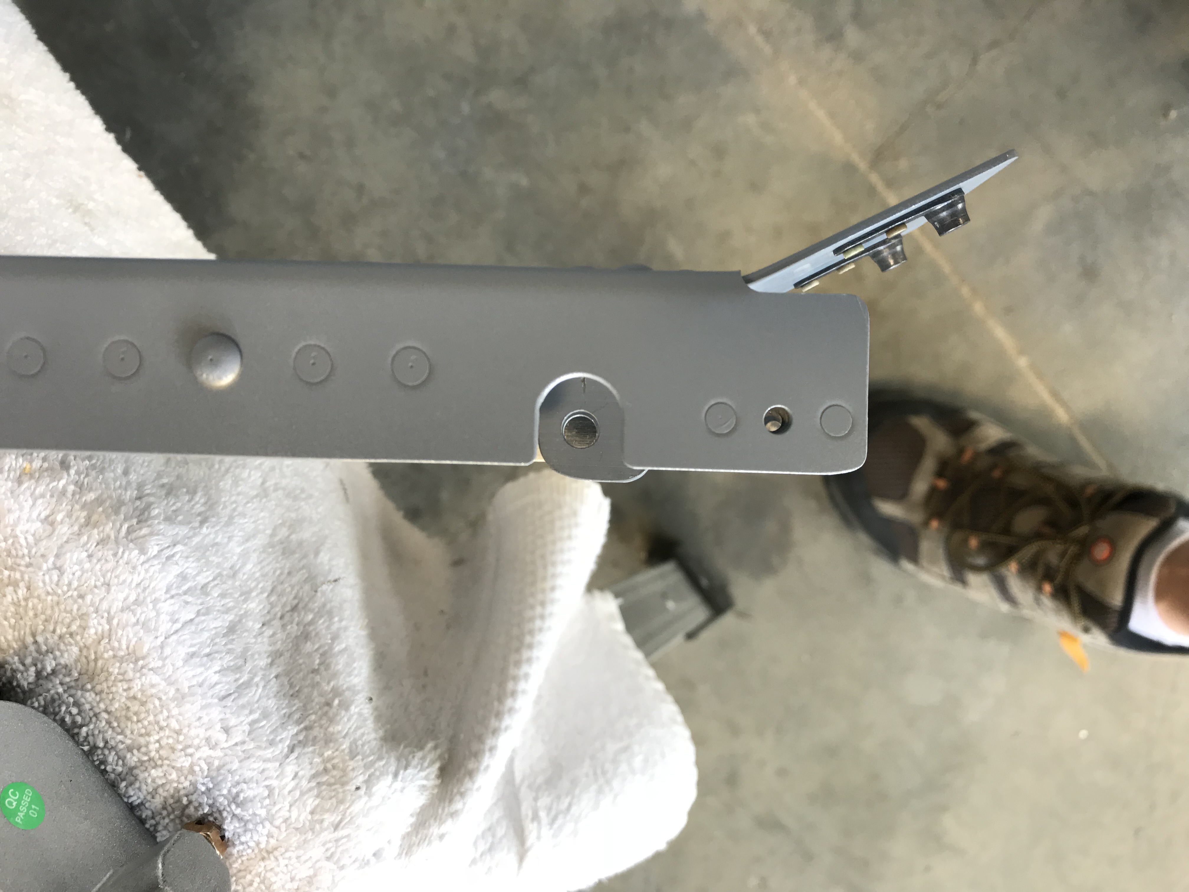
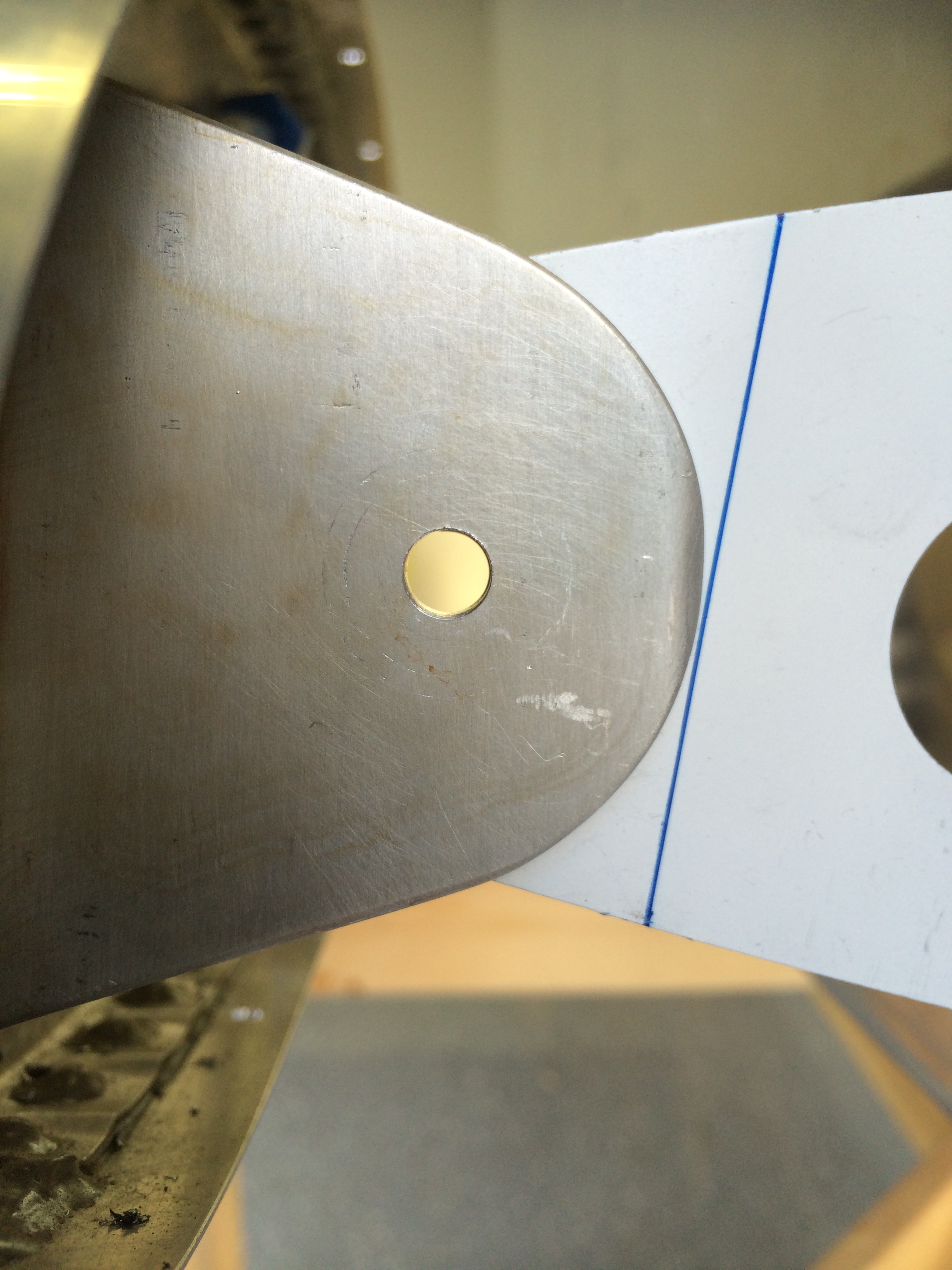
Mark Masse (RV-7 builder) and Rich Snyder (RV-8 builder) work the left wingtip up, down, left and right while Mike Henning (RV-4 builder/flyer) guide the spar into the fuselage and Burt Wadas (best friend) positions tapered stainless steel pins to align bolt holes.

The last left wing install pic

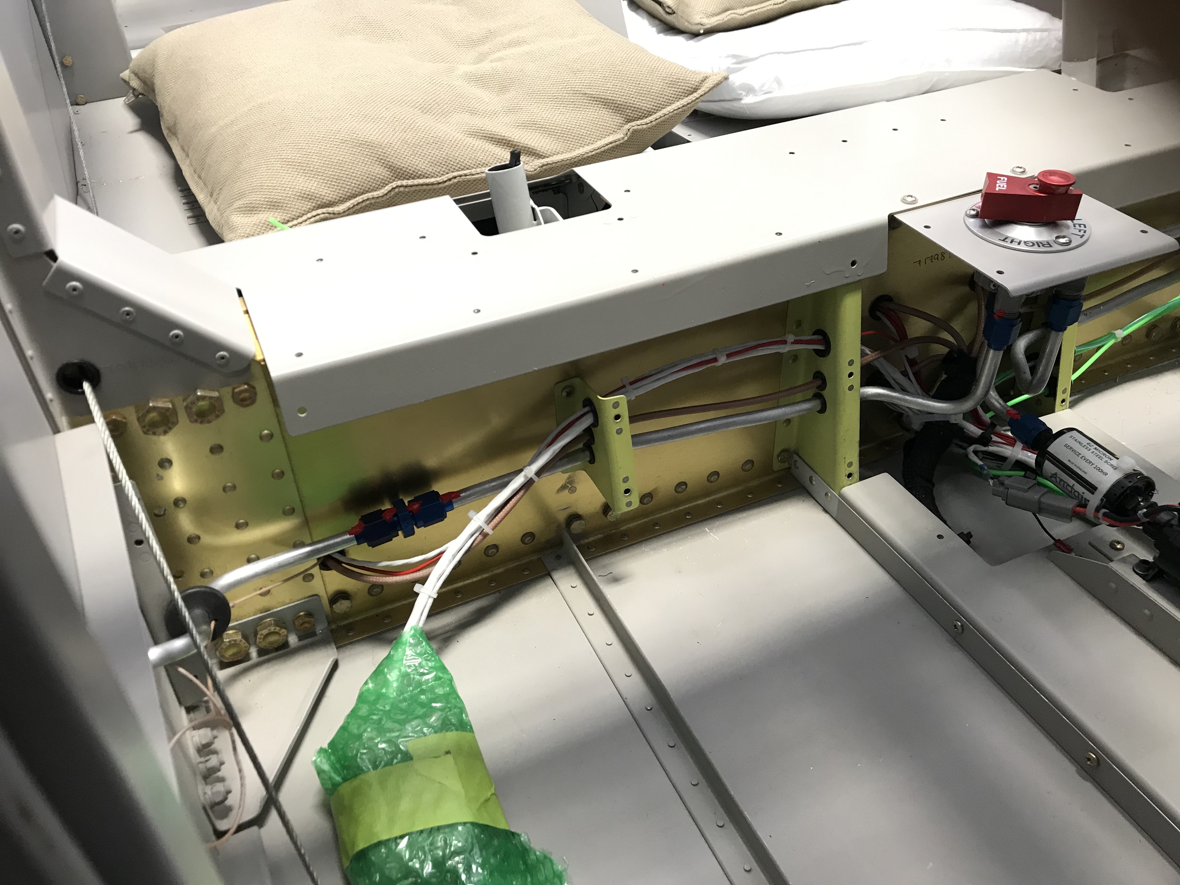
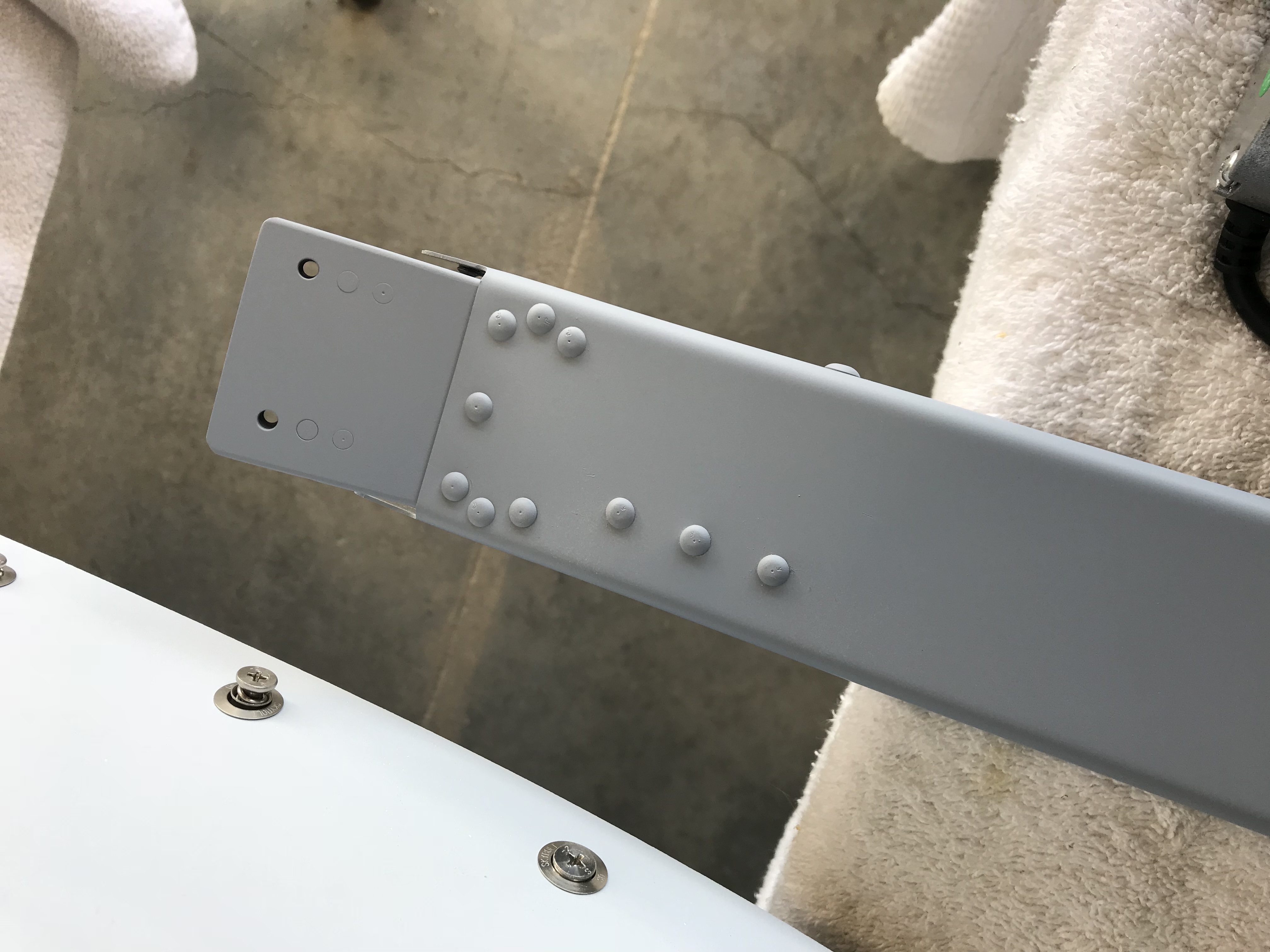
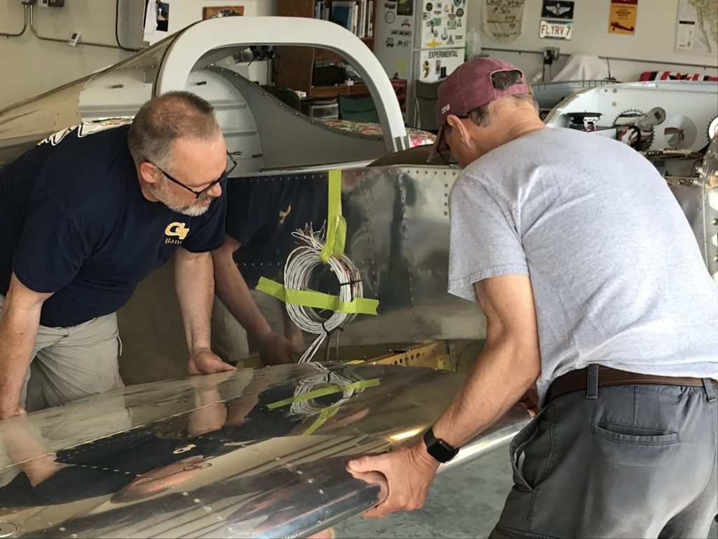
Almost done…there are two close-tolerance bolts inserted now, enough to hold the wing in place til the rest of the bolts are installed.

Right wing install

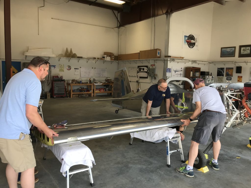
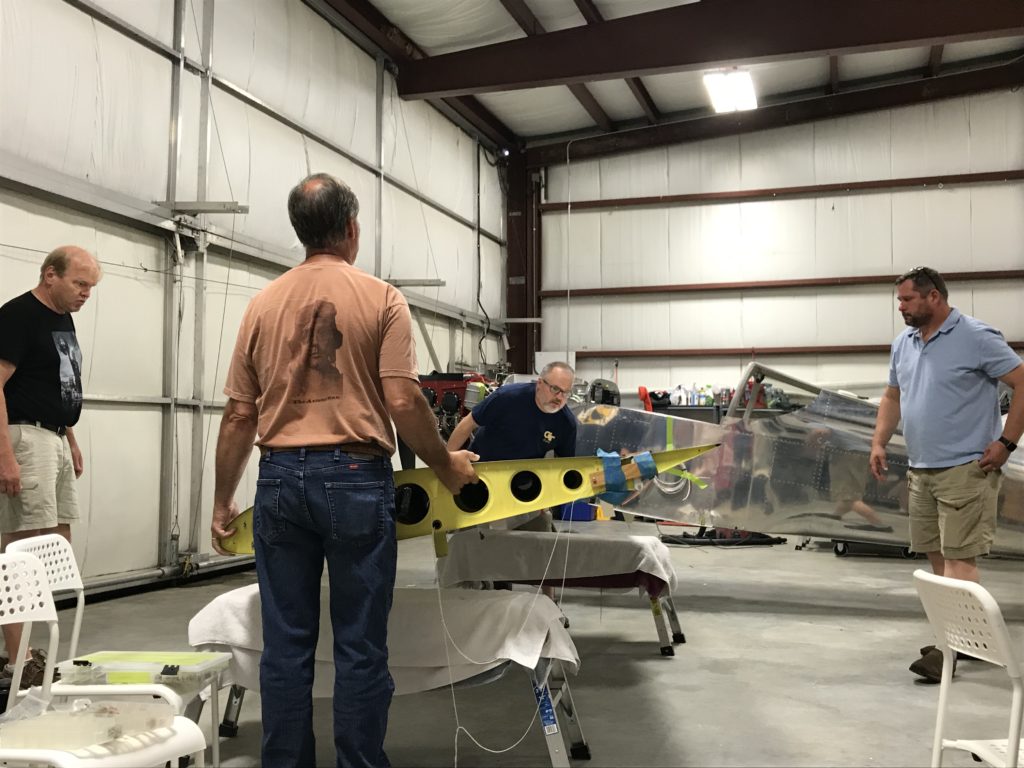
Onto the right wing…same process, but much faster the time.

Another right wing install

You can’t see him in this picture, but Bob DiMeo (RV-8 builder/flyer and my Technical Counselor) is waiting to insert tapered pins in while Burt and I position the wing spar.

Sucking it in...

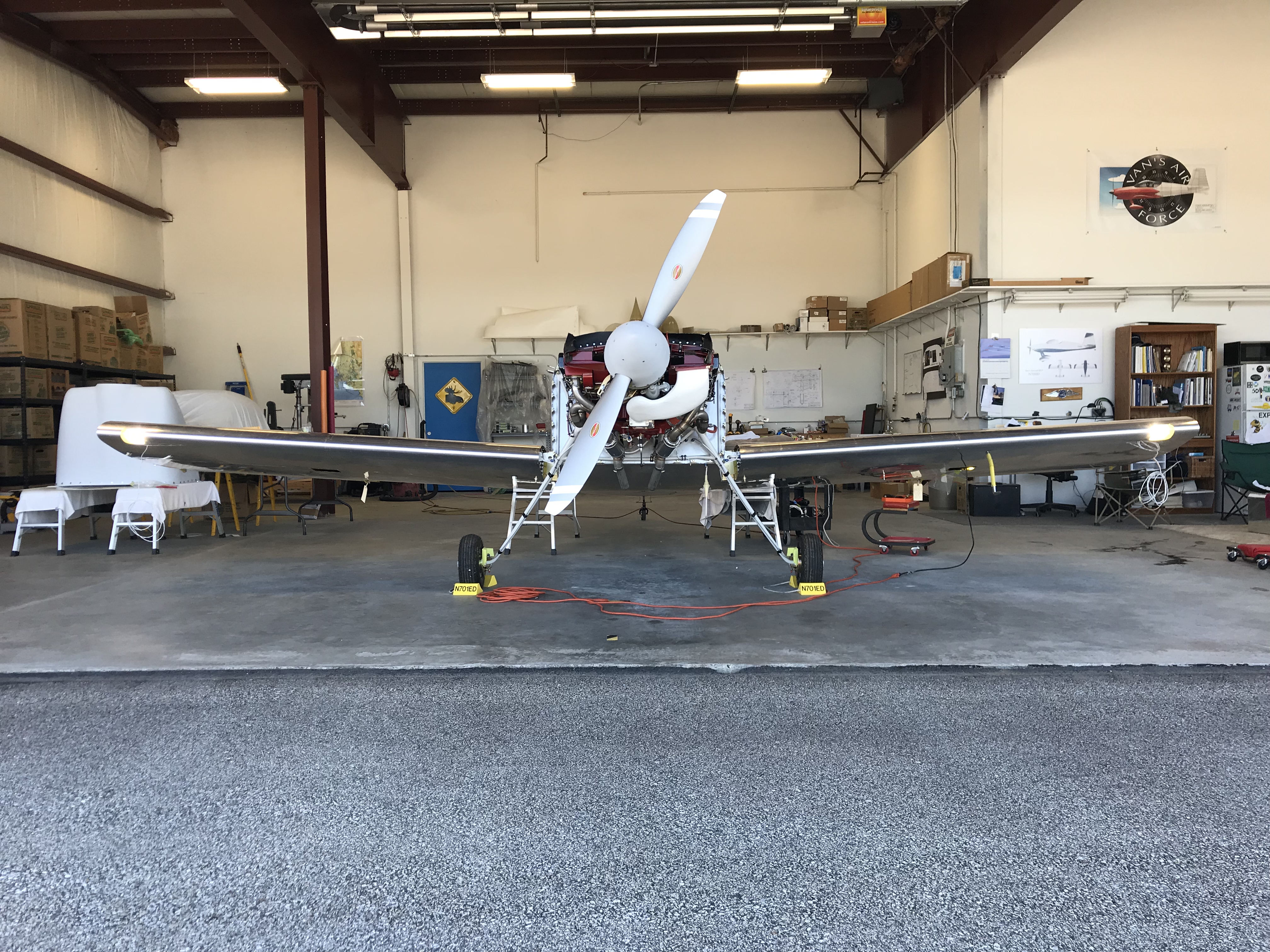
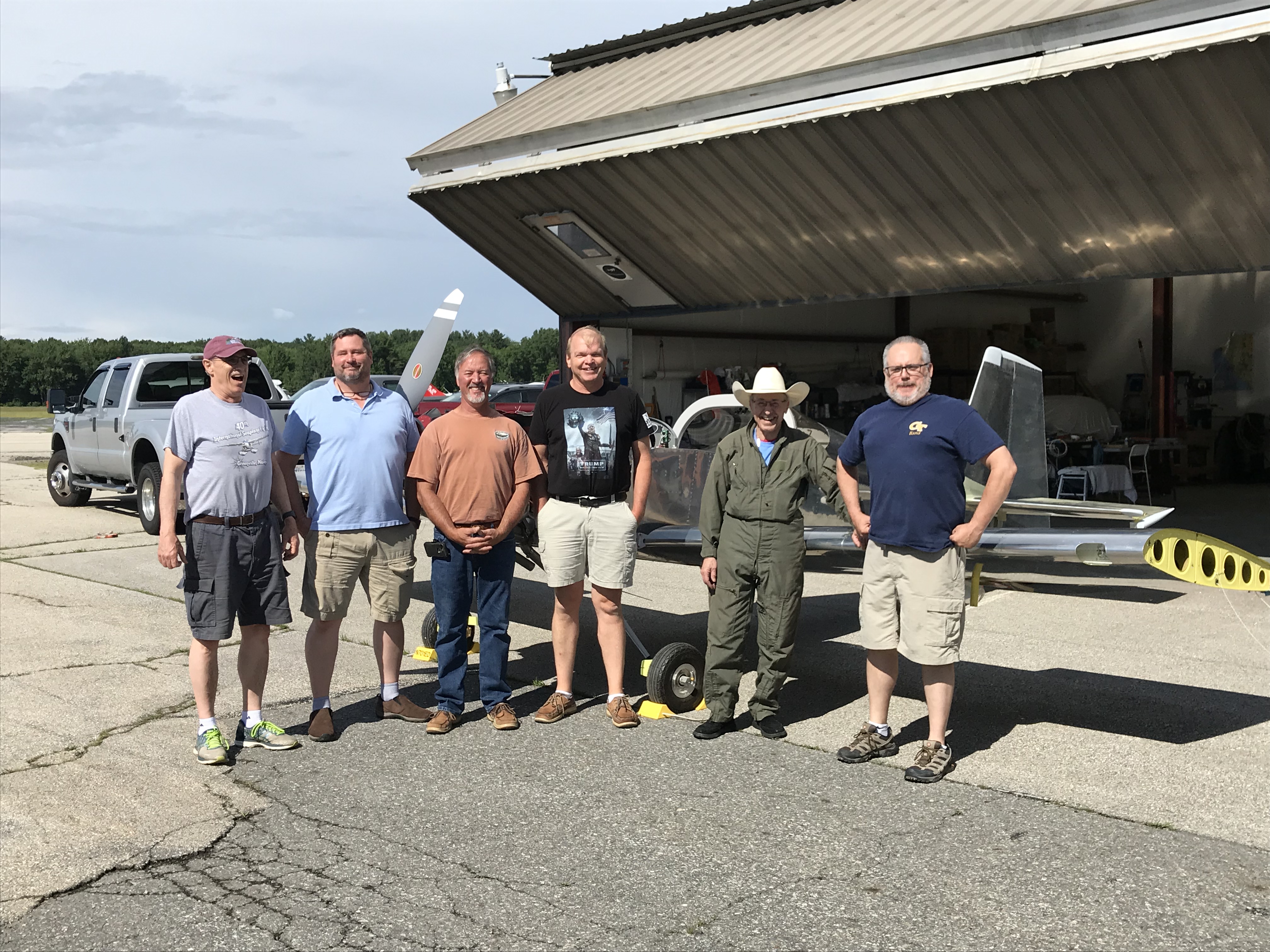
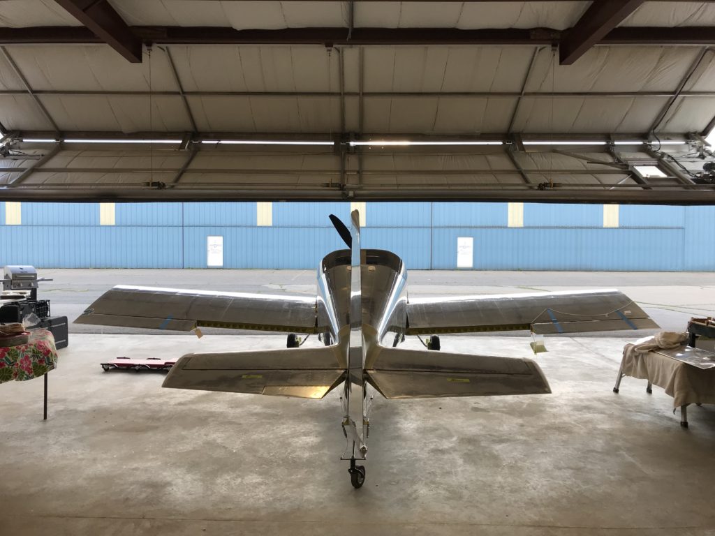
Fast forward an hour or so…the wings are in place and all bolts inserted. Everyone who has a gut is sucking it in for this picture!

B-e-a-youtefull!

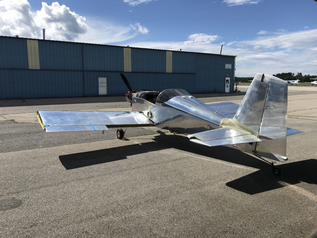
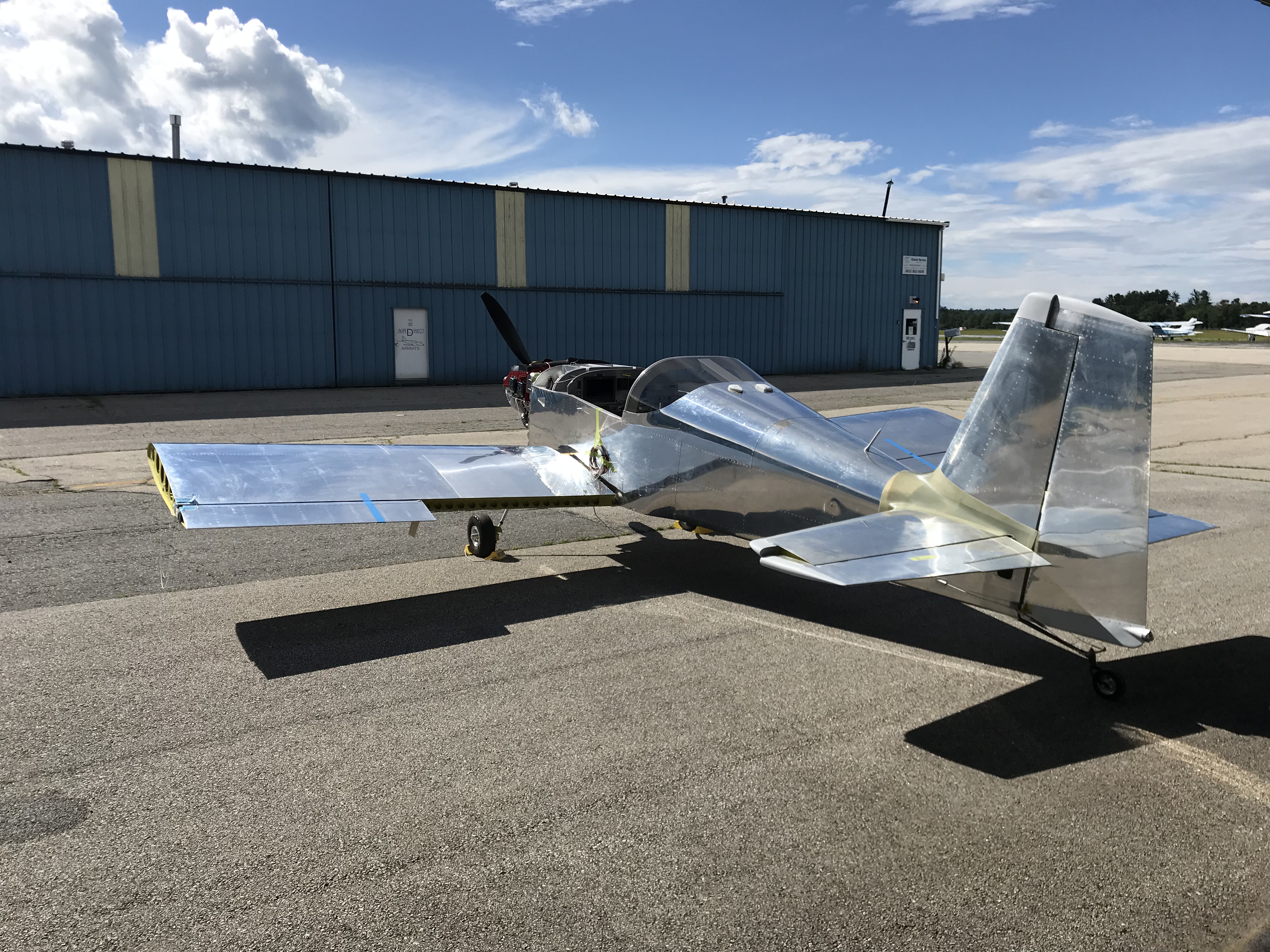
After burgers and beer, Ellen and I pushed the Mighty RV out into the sun for some pictures. Beautiful, ain’t it?

Even more beautiful

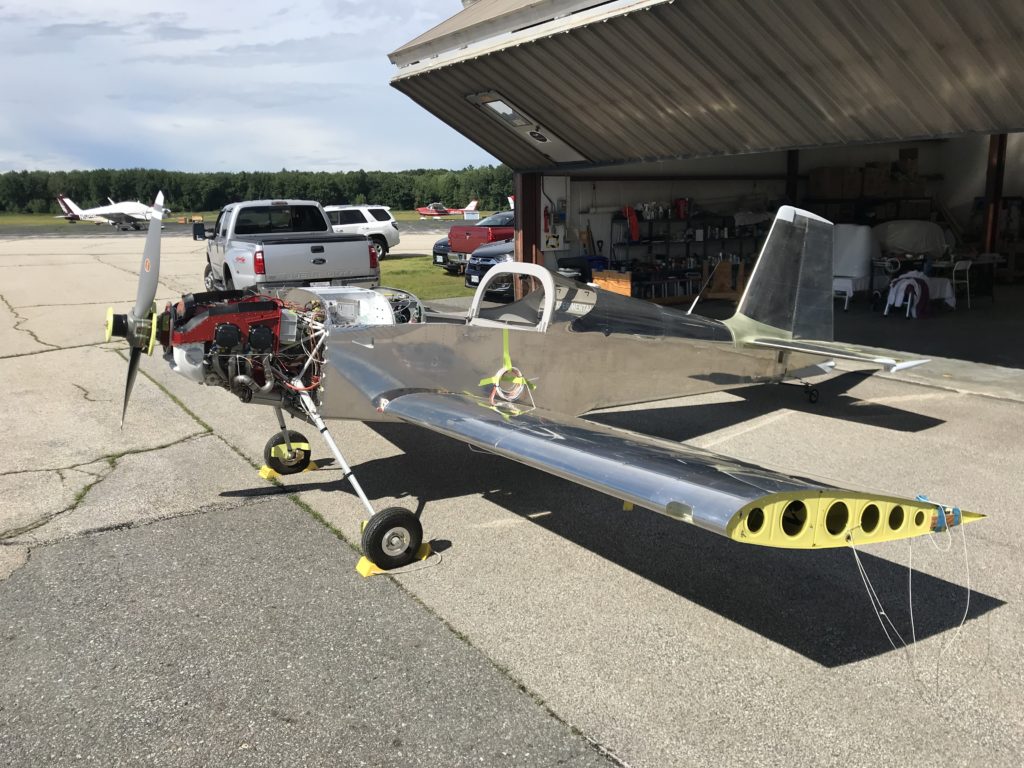
Another picture, I knew you’d ask for it.

Finally beayouteefulAnd finally, a really nice shot captured by Ellen. This is a big day in the life of the project – we’re a huge step closer to flying!

Back to the wings

I’m working on preparing the wings for final installation, and one task that’s easier to perform now is installation of the Garmin GSA-28 autopilot roll servo. Nothing too tricky here, the G3x installation manual covers the process nicely. I’ve had this servo sitting around for a couple of years and it took a bit of searching to find the necessary parts.

Roll servo mostly installedOne gotcha…in the past, Garmin claimed that their servo was compatible with mounting brackets from other manufacturers but that turned out not to be the case. I had originally installed an Advanced/Dynon servo bracket, because way back when I built the wings I was planning to use their avionics.

Turns out that the Garmin servo *isn’t* compatible with Dynon’s brackets, so I had to swap it for the one from the GSA-28 install kit. This won’t be a big deal for anyone who’s installing a servo from scratch, but if you’re swapping from another manufacturer, be prepared for a little extra work.

Full flaps

Continuing on with avionics and cockpit wrap-up, I had to install a microswitch that tells the angle-of-attack (AoA) computer when the flaps are down. Flap deployment changes the coefficient-of-lift curve and so for the AoA computer to work properly, it needs to know when the flaps are down.

Where the flap-down switch resides

The only place I could think of for the switch was right at the front of the flap arm, which is at its lowest point when the flaps are up. I thought I’d do something really spiffy and adjustable…

Flap-down switch, first attempt

…but that didn’t work so well because the bracket (dark grey thing with the black switch attached) was too long and interfered with the elevator pushrod.

Flap-down switch finalGoing back to the drawing board, I put a 90-degree bend in the bracket and rotated the switch so that it’s activated by the flap arm clevis. Works great, and there’s enough play in the switch that I can adjust it later if necessary.

Turns out that was the easy part. This switch grounds a wire coming from the AoA computer, so I had to run a wire from it to the central ground block in the elevator pushrod tunnel. That took most of an evening, but it’s done and the AoA computer now shouts “flaps” through the intercom when the flap-down motor is activated.

Flap motor installed

And here’s the installed flap motor with a Deutsch DTM connector all ready for plugging in to flap power and position sensor inputs for the GEA-24 and GAD-27.

Trimming the starboard stabilizing ailertooters

I have an unfortunate tendency to communicate in movie quotes, so bonus points to you if you can identify the “starboard stabilizing ailertooter” reference without using Google, Bing or some other internet search megalith.

No, the Mighty RV doesn’t have ailertooters but it does have ailerons and that’s what prompted the title. One of the last bits of cockpit work is installing the aileron trim motor; I fitted the bracket way back when I was building the fuselage center section and all that was left was to install the motor and connect it to the flight controls.

Aileron trim installed

I didn’t take any in-process pictures, so all you get to see is the final product. The trim motor is under the square white bracket in the lower center of this picture. It drives a lever that’s connected to the control sticks with springs which are adjusted to be in just enough tension that the motor can move the sticks but not significantly affect roll control feel.

Random tasks…

Finally getting a lot of little cleanup tasks done while the avionics harness is percolating at Approach FastStack.

First, I installed this…

Mystery device

First person to guess what it is gets a ThermosWorks sticker or a free beer at Oshkosh 2019.

Second, I dug out the cockpit lights from Oplite and fabricated a small bracket to mount them on the roll bar support.

Oplite 6sOplite wires

These lights are extremely well-made by my friend and fellow RV builder Rich Mileika. In addition to Oplite, Rich owns and operates Machine, Inc, a precision machining company in the greater Boston area. If you need quality cockpit lighting, try Oplite…you’ll like ’em.

And lastly, I replaced the stock Van’s flap motor with an upgraded version made by Pat Hatch at PH Aviation Services.

This motor has several advantages over the stock unit. The motor and jackscrew are separate so grease can’t migrate into the motor windings, a common problem with the Vans motor. It also has limit switches to stop the motor at full extension on either end, and also has a position sensor to report flap position to whatever device needs it.

The only downside is that the flap support bracket must be modified to accommodate the new motor. Rather than trying to rework the existing bracket, I bought new parts from Vans and started from scratch…only took a couple of hours, and Pat’s motor will save some wiring work later on.

A minor modification

One leftover task from fitting the wings was installing the control stops that limit aileron travel. The plans call for riveting aluminum blocks to the inboard aileron hinge brackets on each wing, and these blocks serve as stops hitting against the steel hinge points bolted to each aileron.

But other builders have a more elegant solution. Turns out a small Delrin spacer, fitted where an aluminum spacer normally goes on those steel hinge points, make a perfect control stop. All that’s needed is some Delrin rod stock of the appropriate diameter, cut to the appropriate width, with a 5/16″ hole drilled in the center to accommodate an aluminum bushing to protect the spacer from wear. When the aileron is at its maximum up travel, the Delrin spacer hits against the top of the aileron hinge bracket.

To me this is a much better solution than having the steel hinge point banging against an aluminum block. Some trial and error is required to find the right spacer diameter – the larger the spacer diameter, the smaller the aileron travel – but checking out other builders’ websites who’ve done this, 3/4″ seems to be a common diameter and that size worked for me as well.

Aileron control stopsBecause I’m an obsessive-compulsive engineer, the spacers had to be precise. As I am wont to do, I threw money at the problem and had a local machine shop bore the holes in the middle of each spacer.  Joe at Coastal Milling Works in Medford MA is happy to take on small milling and machining jobs for a very reasonable cost. After spending too much time trying to center-drill some test spacers, I decided to hand the job to Joe and he handed me back ten perfectly-drilled spacers. If you’re in the Boston area and need some small machining work done for your project, go to Coastal – you’ll be glad you did.

Spacer assembledHere’s the finished spacer, and it’ll go just to the left of the rod-end bearing and washer in the picture above. This little diversion came out very well…much better than the plans aileron stops.

I have a few extra spacers…if you’re contemplating this approach and are interested, let me know.

Fuel vent lines

Ok, I was wrong – there were a couple of other things to do before the wings come off, and fitting the fuel tank vent lines was one of them. Fortunately, these are some of the easiest lines to fabricate. Sorry, only one picture…so not much to report here.

Fuel tank vent lines

Finishing the tank support brackets

One more task on the tank support brackets – drilling holes that accommodate the bolts that attach the tank support brackets to the tank flanges. I copied an idea from fellow builder Mike Bullock and used a 1/4″ OD drill bushing to drill a #40 pilot hole in the tank angle. The bushing fits snugly in the 1/4″ cutout on the tank support bracket, ensuring that the hole is nicely centered.

Tank support drill bushing

Here’s the bushing clamped in place on the aft side of one tank bracket…

Drill bushing clamped

I then used the #40 hole to center a 1/4″ drill bushing on the front to the bracket, held in place by a piece of 0.25″ aluminum bar.

Larger drill bushing

Here’s the final result…both sides came out pretty nicely.  A 1/4″ bolt slips neatly into place.

Final hole drilledI screwed up a little and didn’t lay out the orientation of the platenut that gets riveted to the tank angle – I’ll have to take care of that when the wings go on for final assembly.