Balancing Act

The last major task on my to-do list was balancing the elevators. Van’s instructions aren’t super clear on whether to do this before paint, but a call to Sterling at Van’s confirmed that the elevators must be balanced before first flight. Works for me.

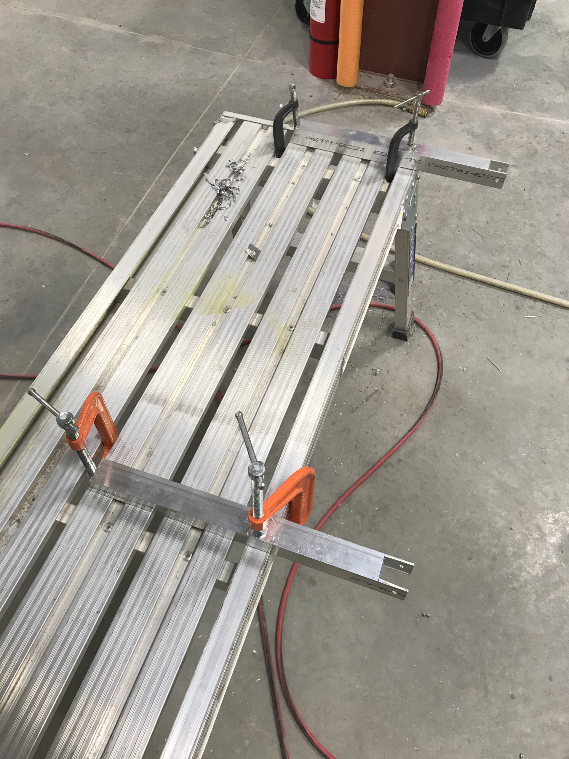
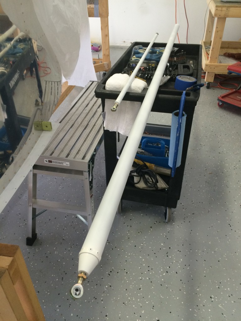
I decided to put together a simple rig for balancing – two pieces of aluminum box extrusion trimmed and drilled at one end to accommodate elevator hinge bearings and bolts to hold them in place, both clamped to an aluminum work support. Here’s a pic –

Elevator balancing rig

The left elevator needed some weight and I had to remove some from the right elevator.

With balancing complete the elevators went back on the airplane and the airframe exterior is DONE!

Wiring from the tail forward

There isn’t a super-convenient way to route pitch trim and magnetometer wires into the empennage, so I improvised…

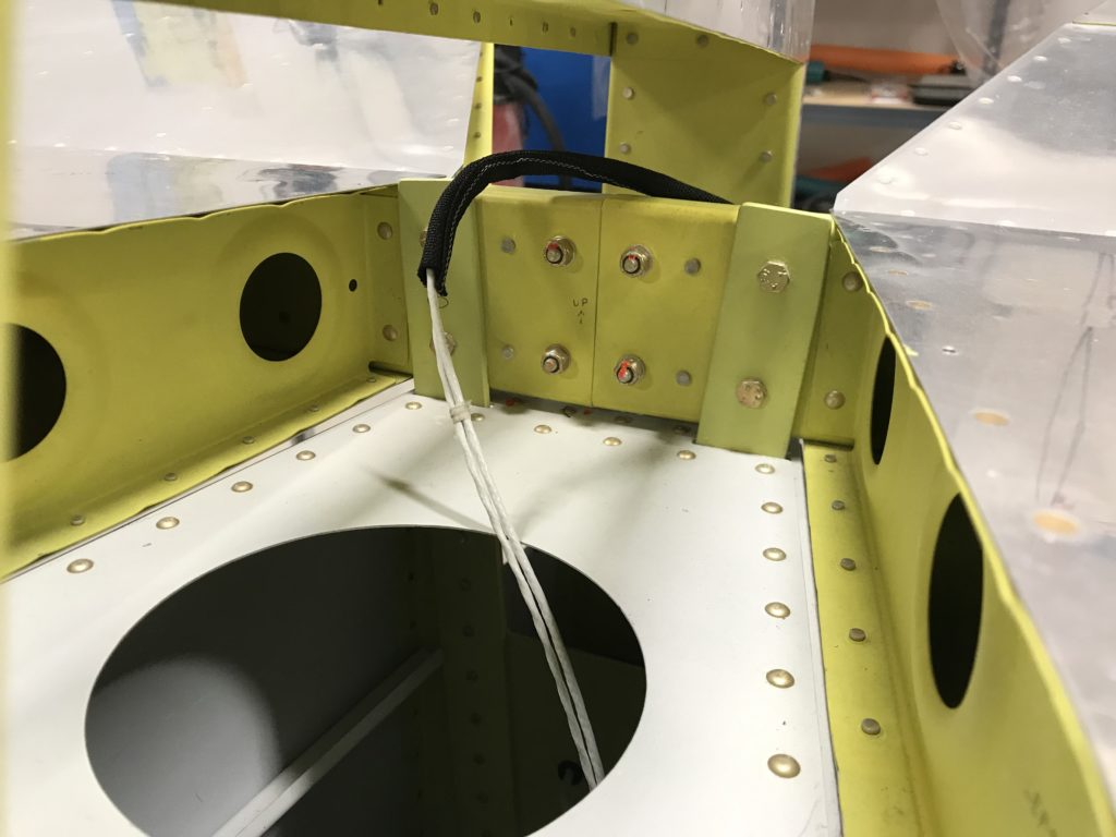
Here’s the pitch trim servo wire exiting through a lightening hole in the fuse rear deck.

Routing the pitch trim wire

I liberally applied adhesive zip-tie mounts to the rear deck and glued a small piece of aluminum angle to the rear spar with 3M 4000 marine cement (easier than riveting) to hold another zip tie.

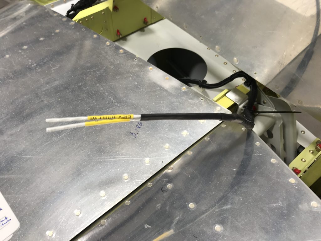
Pitch trim wire over the HS sparThe black material is self-closing anti-chafe wire bundling I found at McMaster-Carr. The plans call for running trim wires along the front of the left elevator and into the trim servo bay. I think this is better than running wire through the existing manual trim cable holes as repeated elevator movement over time slightly twists the cable rather than bending it – much better from a wire fatigue/failure perspective.

Routing pitch trim wire into the elevator

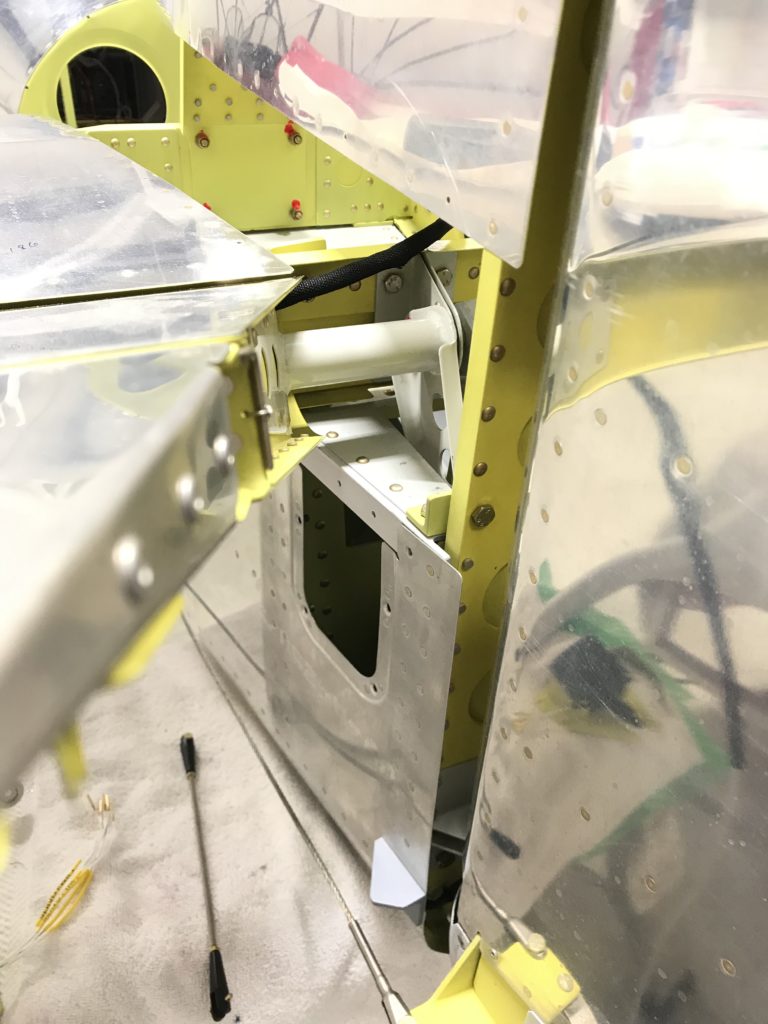
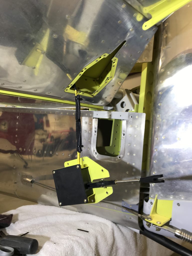
You’ll see in this picture how the trim servo cable is routed into the left elevator and why some support is necessary where the cable crosses the HS rear spar.

Pitch trim servo ready for installation

And here’s the wired trim servo ready to be stuffed into the elevator. It’s slightly tricky to route the cable so it doesn’t interfere with the servo’s jack screw, but I think I’ve managed to get everything done correctly.

A happy New Years at the ThermosWorks

After more than 12 years, the rudder and elevators are mounted to the empennage and they’re moving freely without binding. Took a lot of fiddling with washers and spacers, and some expert help from my Tech Counselor (thanks Bob!) to make that happen, but it’s done.

Here’s a short demo of today’s work…

A few tips

I’m awaiting delivery of the avionics harness from Approach Fast Stack so I decided to tackle a task I’ve been avoiding for more than 13 years – fitting fiberglass tips to the horizontal stabilizer, elevators, vertical stabilizer and rudder. I’ve said before that I hate working with fiberglass and that’s still the case.

Van’s ships the elevator tips with no front end and recommends fairing over the counterweight with an epoxy/flox fill, essentially making it non removable. I decided to add a thin fiberglass layer over but not attached to the counterweight so that I can remove the tip later on if necessary.

Tip prep was simply sanding down the front surfaces to give the layup something to bond do.
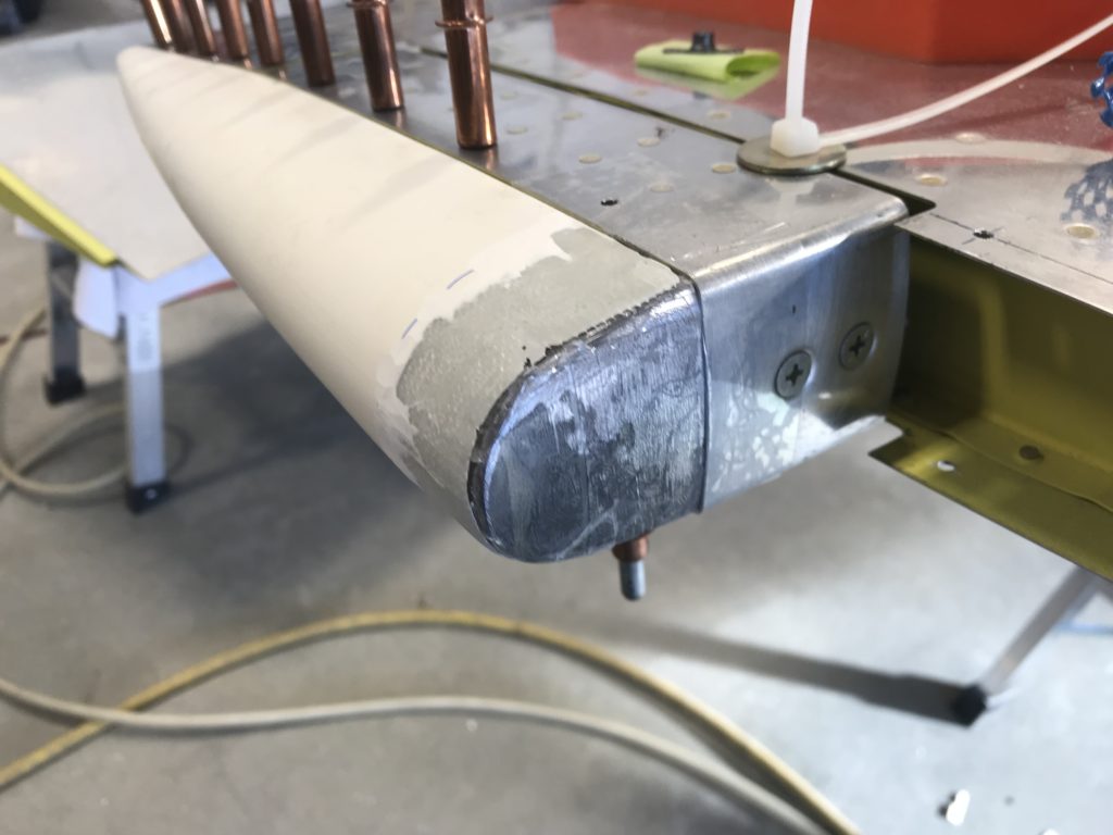
Elevator tip prepped

I laid up 3-4 layers of 9 oz BID cloth over the counterweights and front of the tip. Before doing that I covered the elevator and counterweight with clear packing tape as a mold release.
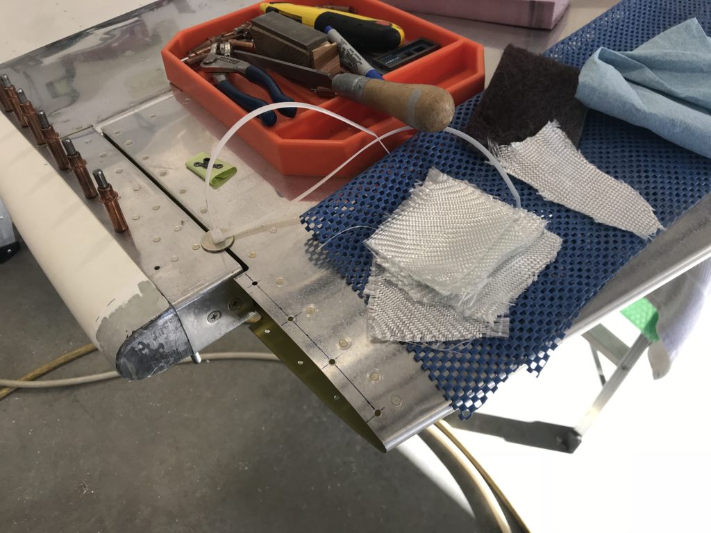
Fiberglass ready to apply

The layup initially looked too thick but when I sanded it down to match the elevator and HS tip there wasn’t much left – but there really doesn’t need to be.
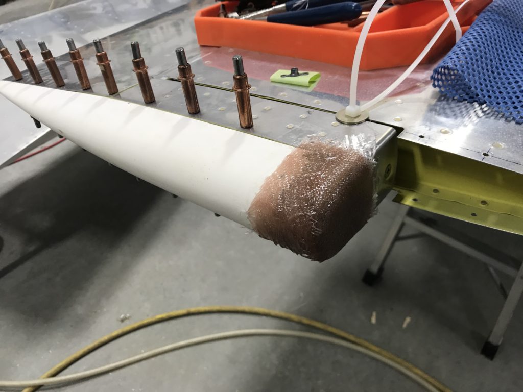
Initial fiberglass layups

Here’s the inside of the tip after removal..it conformed pretty nicely but I had some voids in the cloth that required some additional epoxy to fill.
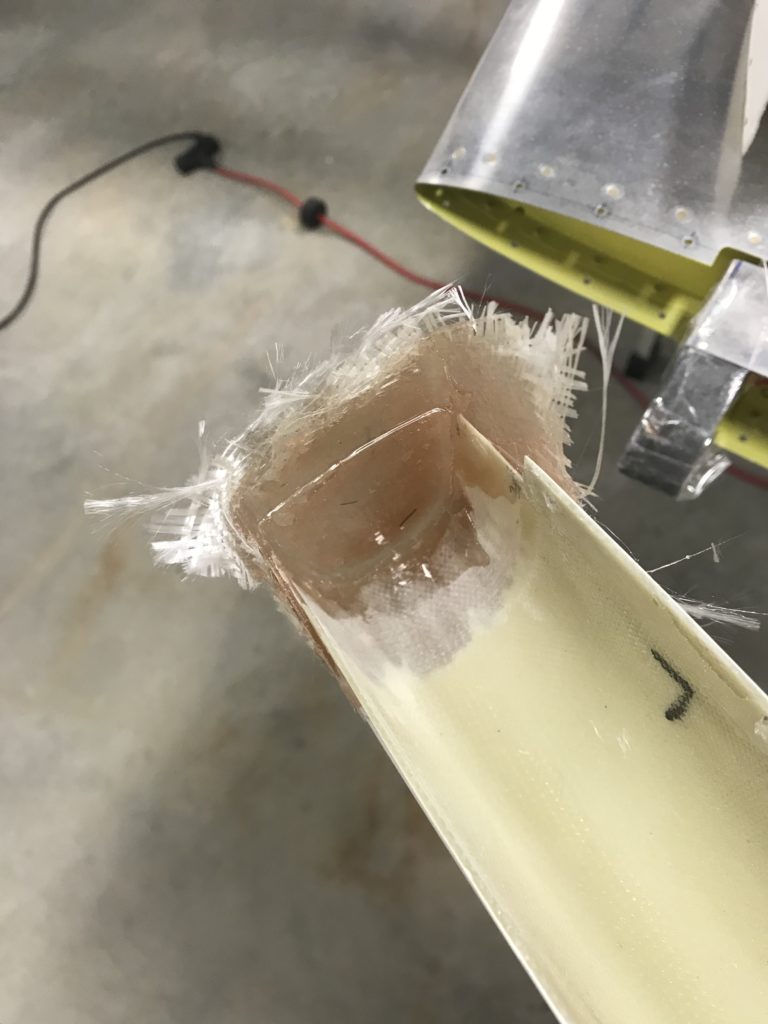
Interior of tip after removal

After sanding and before priming…looks good!
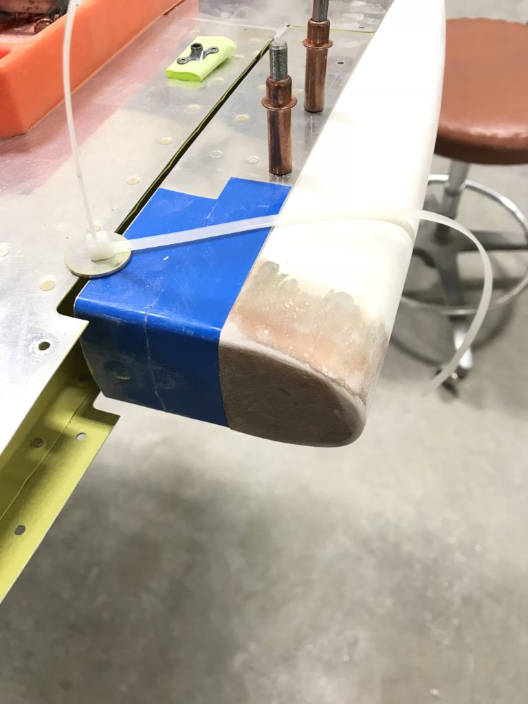
Finish-sanded tip

The HS tips come without a back end and there’s no requirement to add one but they look better and more “finished” if they’re closed – so that’s what I did, using the foam technique in Section 5 of the instructions and and a sheet of pink foam insulation from the aircraft construction department at Home Depot.
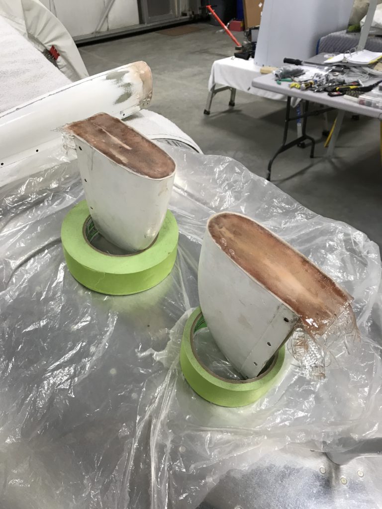
HS tips covered

The same foam closeout technique was used on the VS tip…already done in the pic below.

The rudder upper fairing was a really poor fit, a common complaint with previous versions of fiberglass parts shipped by Van’s. I had to build up the front end with balsa and fiberglass, and apply epoxy and microbaloons to fill gaps on either side.
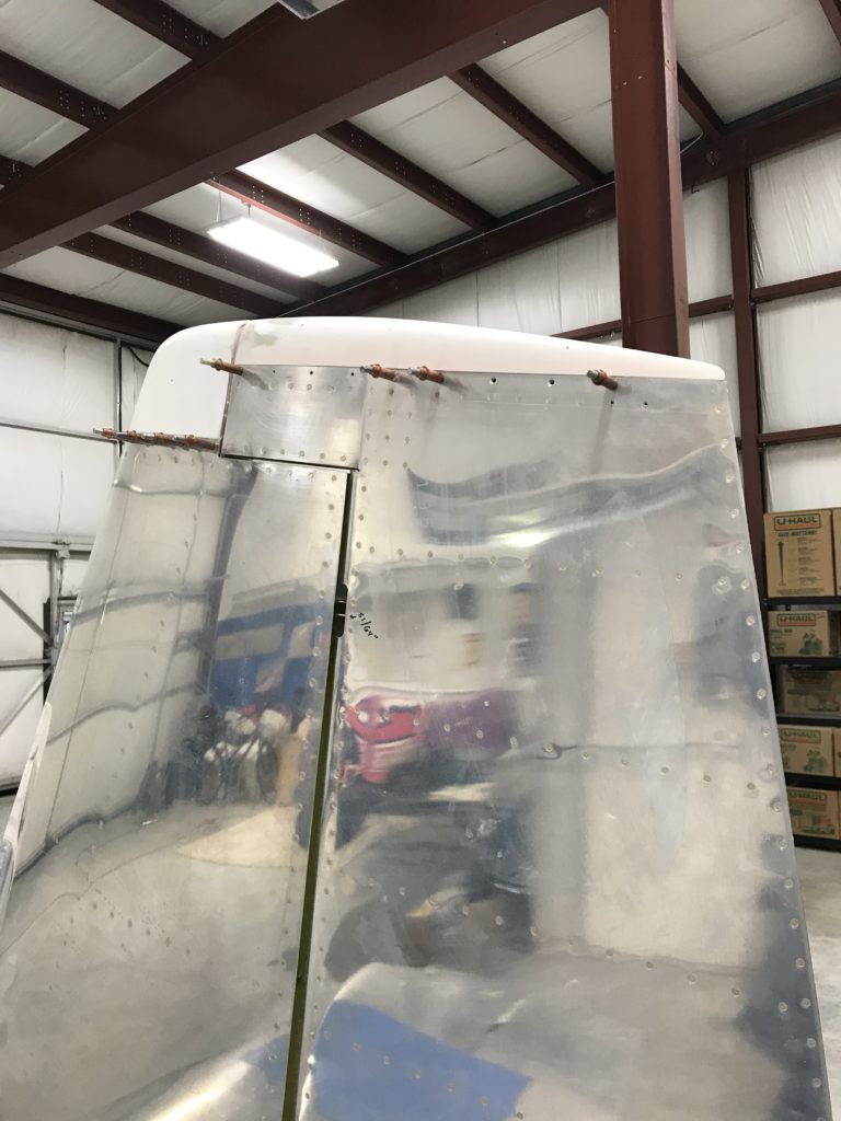
Upper VS and rudder tips

Surprisingly, the rudder lower end cap fit pretty well when trimmed to the scribe marks applied by Van’s. I decided to make it removable by adding #6 platenuts to fairing attach points on the rudder.
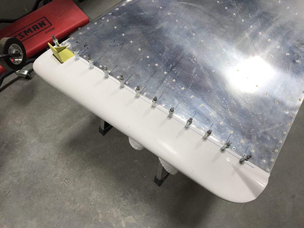
Lower rudder cap

The lower end cap looks good now, but pop-riveting the nav/strobe light attach plate caused the fairing to crack (shit!) so I had to mix up some epoxy and flox for a fix.
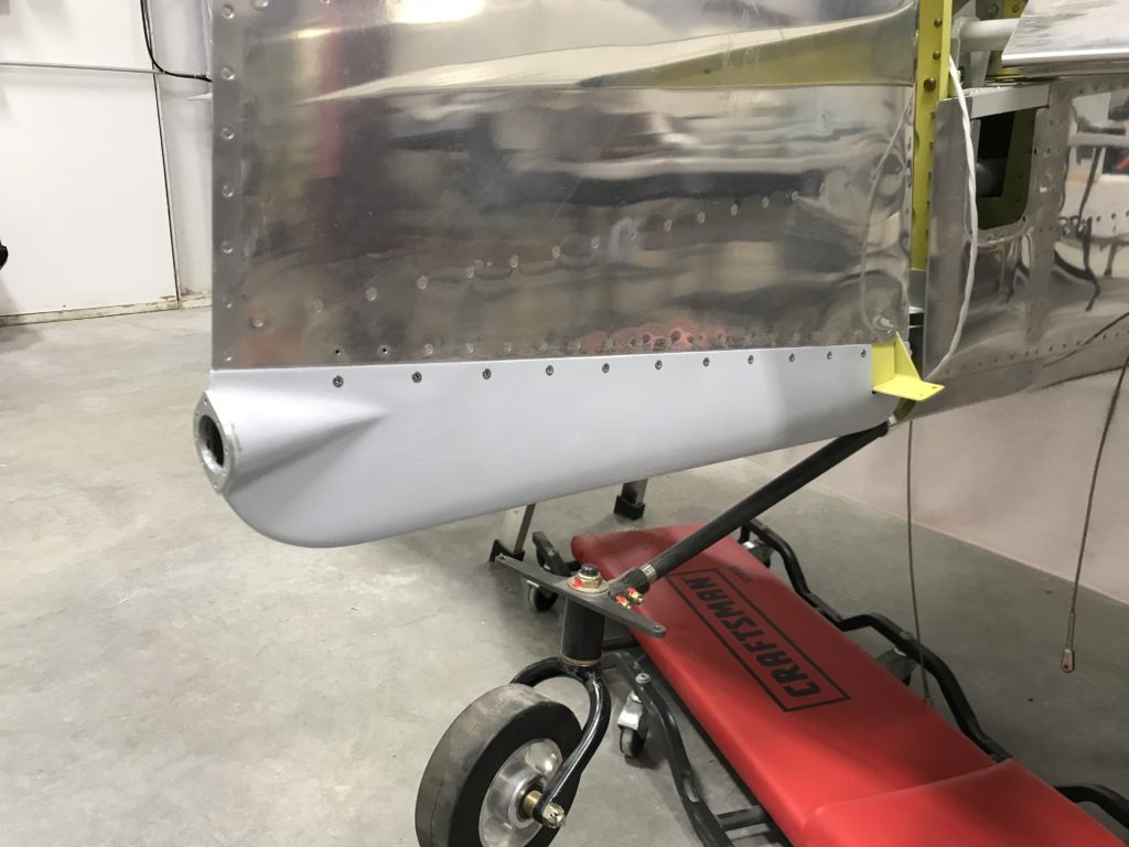
Lower rudder tip fitted

Here are all the emp tips sealed and primed with K36 primer to protect them until time for paint.
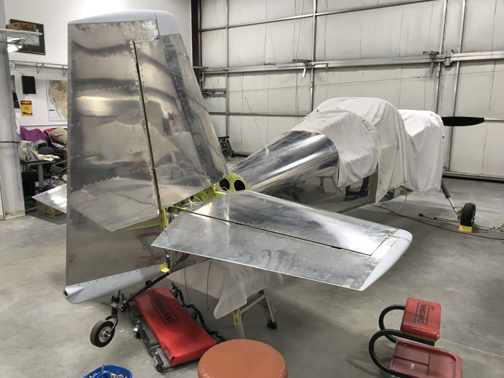
"Finished" emp tips


Rolling the leading edges

Ahh…my favorite part of control surface building – rolling the leading edges. I used the same procedure described earlier on this page, plus some liberal application of hand-tweaking to make the overlap as smooth as possible. This one came out better than the other side, I think.

More fun with surface rolling

Riveted the trim tab hinge

My disease seems to have abated somewhat, so I spent some time downstairs and riveted the trim tab hinge to both the tab itself and the left elevator. The pneumatic squeezer is the weapon of choice for setting these rivets, but I had some problems getting the flush set to fit between the spar web and some of the hinge eyes. If the flush set is too far forward it can push on and bend hinge eyes, not a good thing. And surfing through the Van’s Air Force forum, I found others had the same problem. My solution was to take a spare flush set and grind it down a bit to reduce its radius. Worked great!

Here’s the trim tab, essentially complete.

Trim tab done

The riblets came out fine, I think.

Trim tab riblets

Elevator trim cutout riblet blind-riveted

Over the weekend, Ellen and I got the trim tab fitted to the elevator and the hinge drilled. After some primer touchup, everything was ready for final riveting. At least that was the plan. I came down with some bizarre stomach bug and didn’t accomplish much. I did manage to get the elevator trim cutout riblet blind-riveted…

Elevator riblet done