Fellow RV builders know that as we closer we get to the end of our projects Van’s plans and parts become a little more “generic” – parts probably don’t fit precisely and we have to read between the lines in the instructions to figure out what needs to be done. Such is the case with the engine baffles. Van’s baffle kit is actually quite an improvement over the one they previously offered for the RV-7 but because the fit of the baffles is affected by the cowling and intake plenum/induction scoop, and because no two engines are exactly the same, quite a bit of work is required to make the baffles fit correctly.
As I write this the baffles aren’t completely installed so I’ll be adding pictures later as I finish painting and installing them.
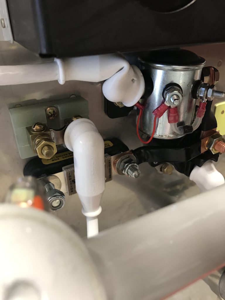
 Where else should we begin but at the beginning? I started by match-drilling the aft left side baffle, and also adding a heavy 1/8″ angle to provide some additional support for the oil cooler which will later attach to it. This is a notorious weak spot in the baffle system; as designed by Van’s there’s just too much flex to support an cooler that’s full of oil and being vibrated by turbulent air and the engine. Because the angle interferes with an existing reinforcement angle (at top, with the “U” shaped notch in the middle), I added a piece of 1/8″ stock in addition to the reinforcement angle.
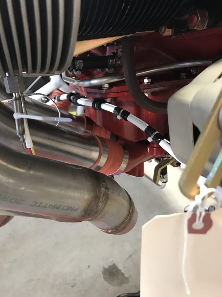
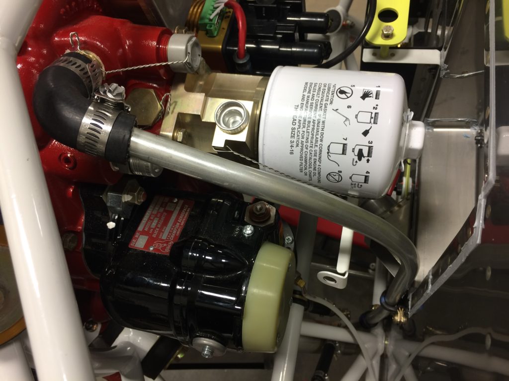
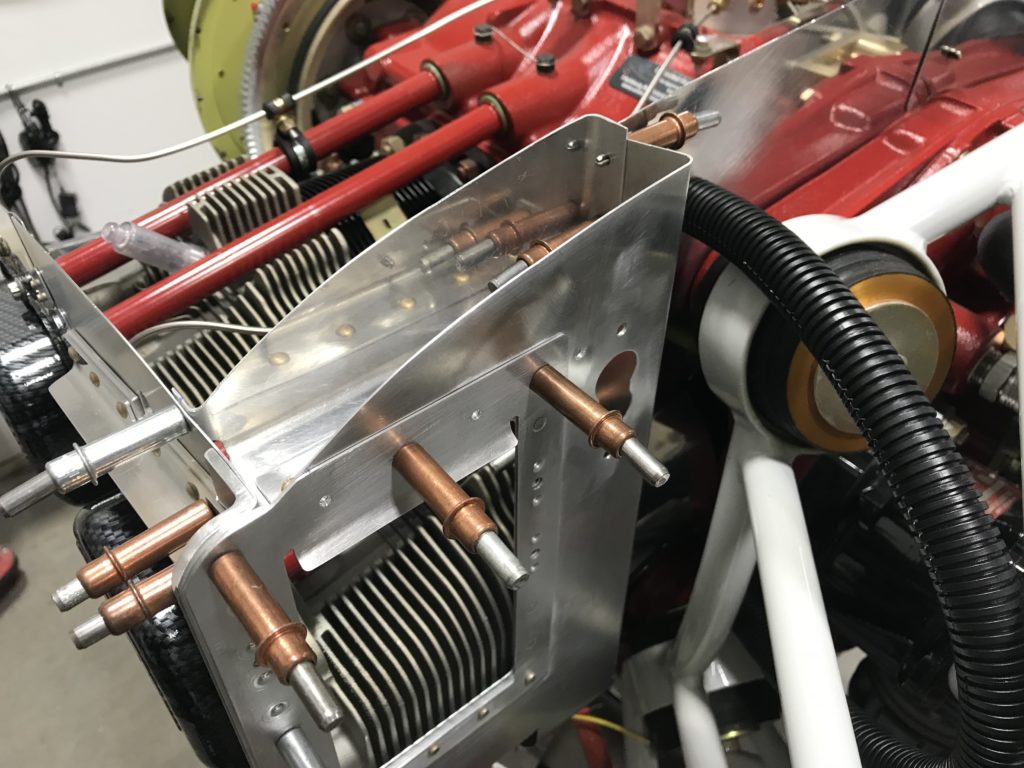
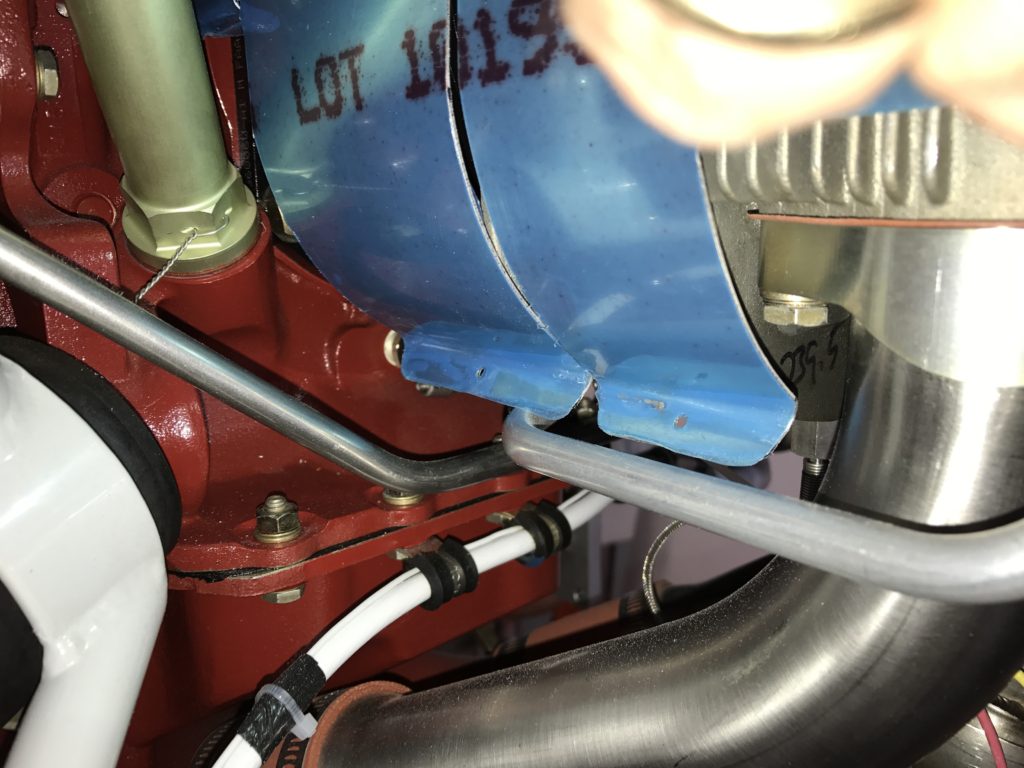 The right rear baffle – behind the #4 cylinder – was a tough fit. The oil return lines are fairly close to the cylinder and getting the baffle flanges to squeeze between the cylinder and return lines was tricky.
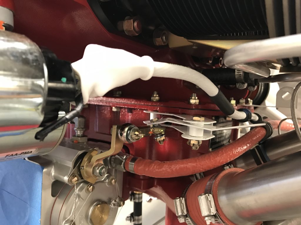
 Fitting the side baffles was reasonably straightforward. I had to file some material away from the valve cover cutouts to make the baffles fit around them. Not a big deal, just a bunch of iterative fit-file-repeat to get things right.
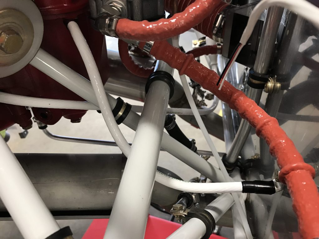
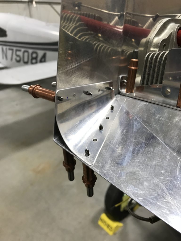
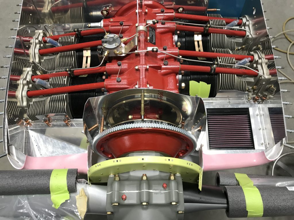
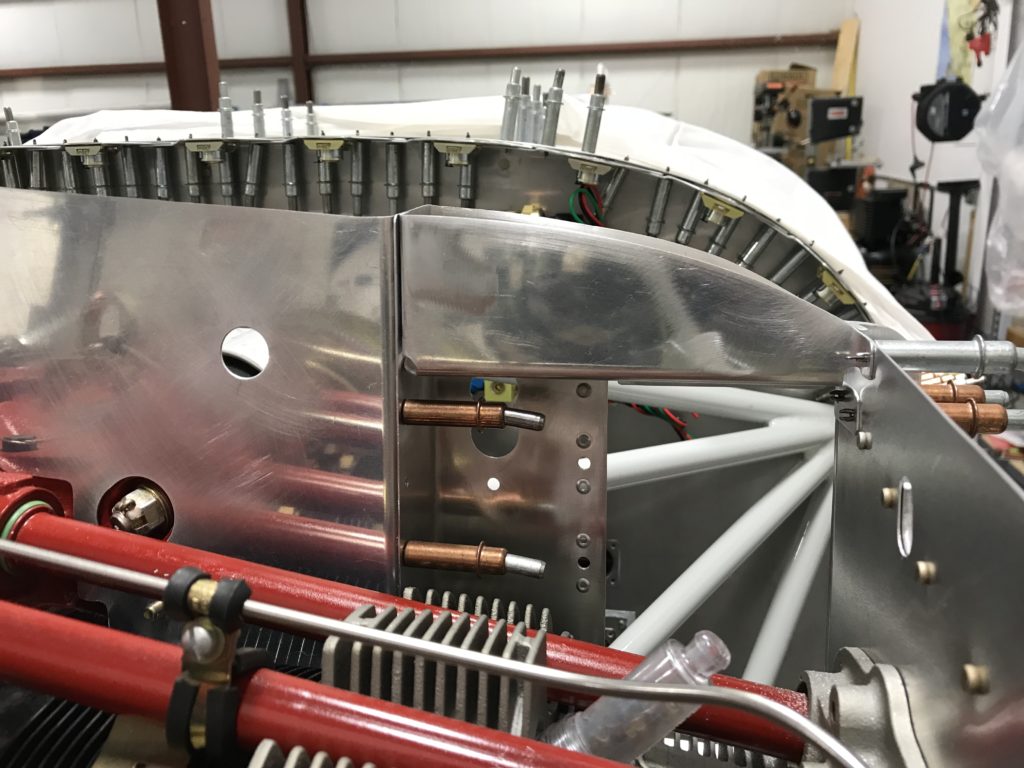
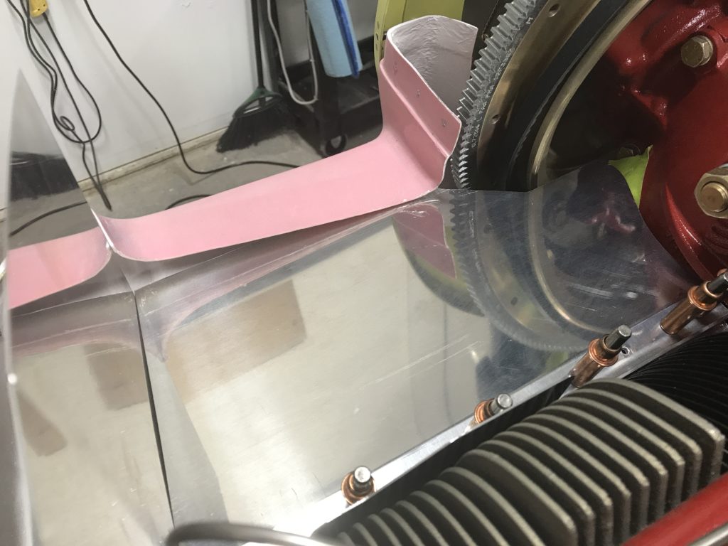 The front baffle ramps are slightly tricky. Van’s instructions call for a diagonal bend from the aft outboard corner (lower left in this pic) to the forward inboard corner (top center in this pic, right next to the starter gear) to close the gap between the ramp and lower cowl lip. This is straightforward on the right side, but the left side is more complex due to the opening that needs to be cut for the horizontal induction filter intake.
 Here’s the horizontal air intake “snorkel” already drilled in place to the fuel injection servo. There’s not much to this, just follow Van’s instructions. The key is to maintain a minimum 1/8″ distance between the inner snorkel surface and any nearby engine components like the starter.
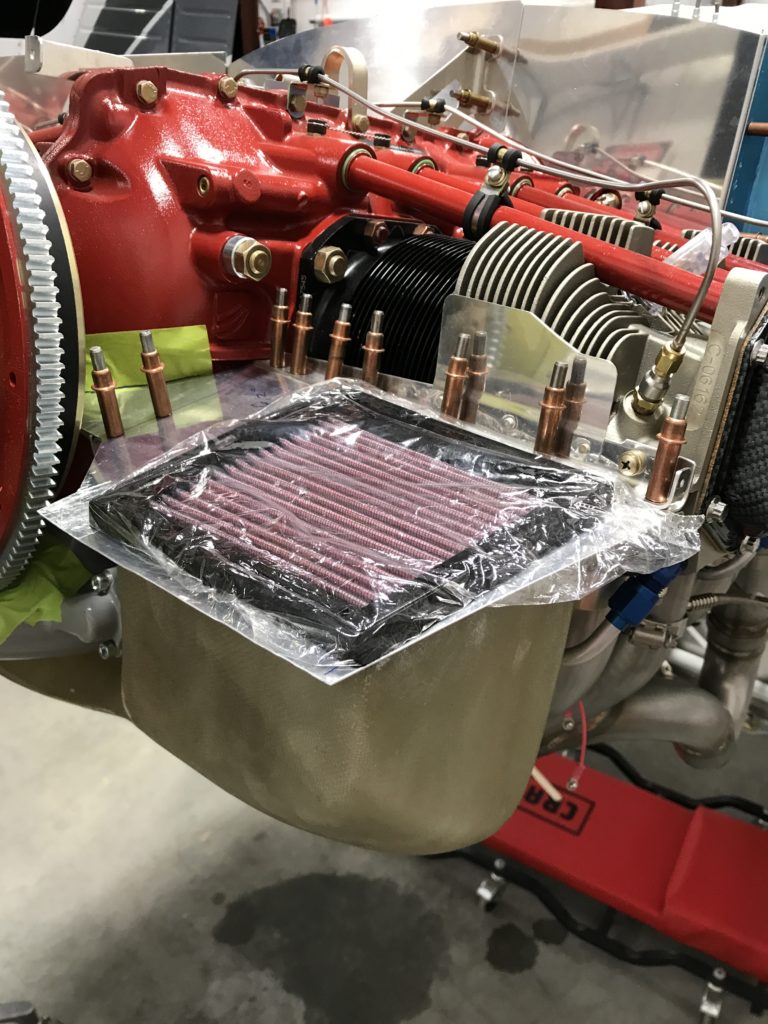
This is my first attempt at fitting the front left ramp; in this pic the filter is actually lying on top of the ramp – when complete, the filter’s top surface will be flush with it. I traced the filter opening on the underside of the ramp using the snorkel as a guide, then cut the opening.
One of the tricky aspects of this is that it’s still necessary to make the diagonal bend it the ramp that I mentioned earlier to make it fit with the cowl, while also making the ramp bend in such a way that the filter will lie snugly next to it. The filter will twist diagonally (i.e., the inboard and outboard edges won’t be parallel) so it should conform to the filter mounting brackets if the diagonal bend is made from the forward inboard corner to the aft outboard corner of the opening. I spent a fair amount of time on this after making the initial rough cut of the opening, removing lower cowl several times and adjusting the diagonal bend to get the front ramp edge positioned correctly. When necessary, I removed the snorkel and trimmed its upper edge to conform to the ramp.
It took a bit of 3D thinking to work all this out and once I had a good idea of what was supposed to happen, I ended up ordering a replacement front left baffle from Van’s. It was easier just to start over.
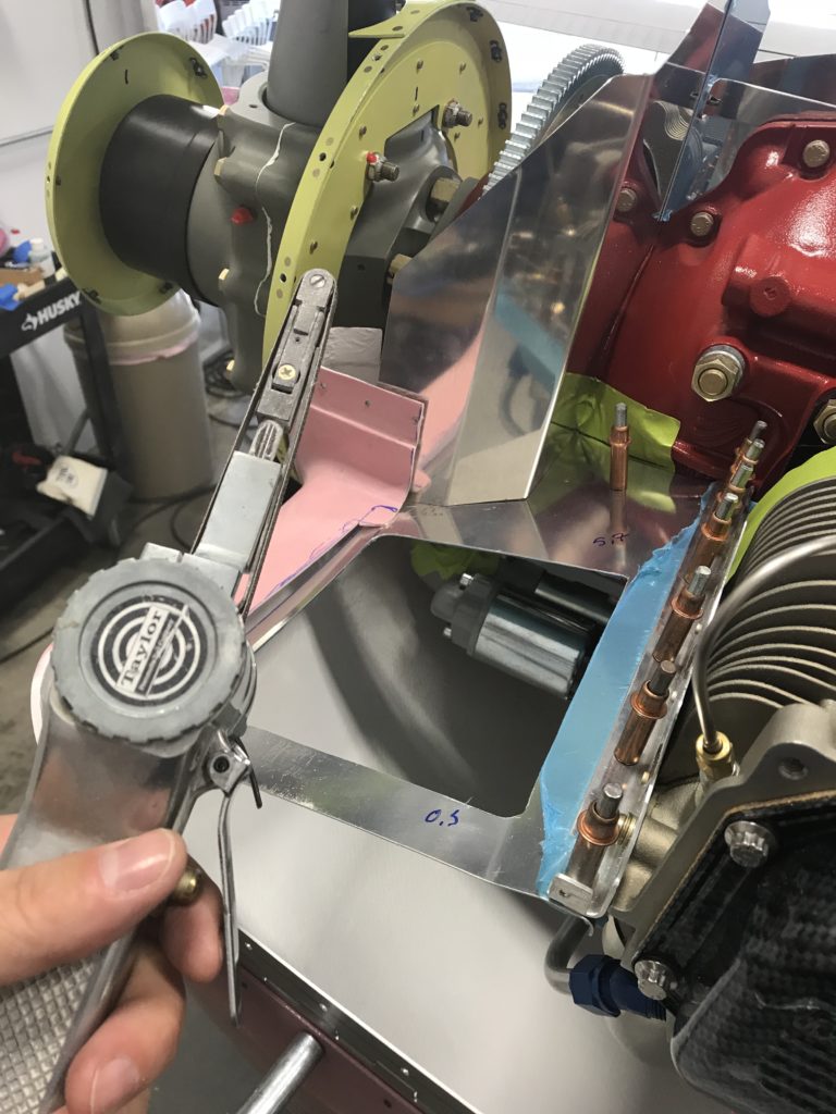 My friend Mike lent me his Taylor air sander for trimming the cowl and ramp. This thing is the berries – it makes short work of tasks that would ordinarily require a lot of filing and sanding. I used it to smooth rough-trimmed edges in the ramp opening and also to remove some of the lower cowl lip to accommodate the ramp’s front edge.
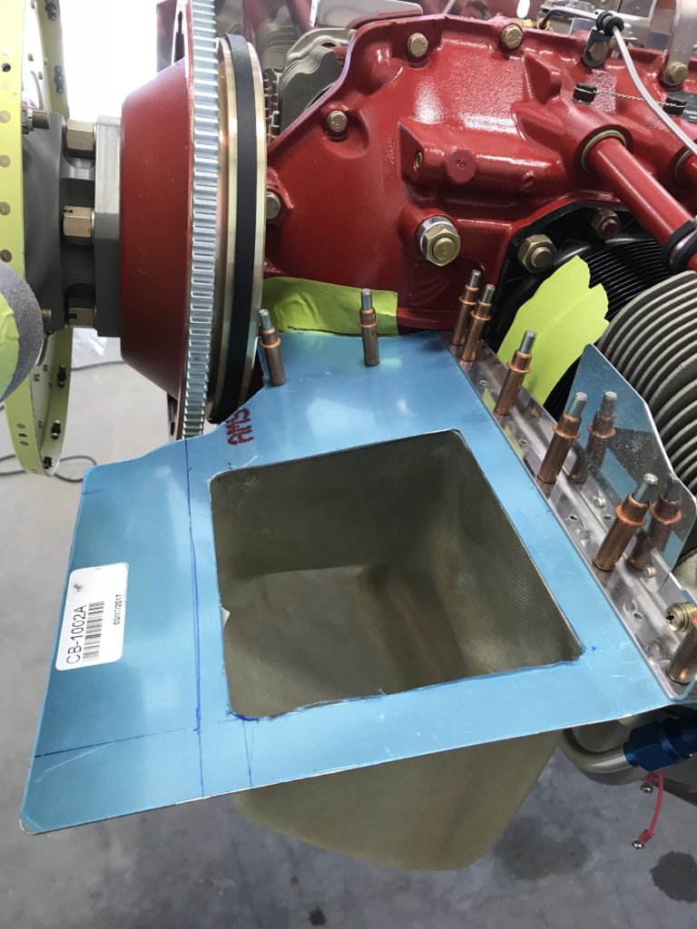
 As you might be able to tell, I had to remove some of the lower cowl intake lip (right in front of the filter) to eliminate interference with the CB-1002A when removing and reinstalling the lower cowl. If you’re working on this area, don’t trim the cowl until you’ve determined the final cut line on the -1002A front edge.
At this point I also marked the outline of the filter flange onto the ramp for final trimming of the filter hole.
 At this point I was getting pretty burned out on the left ramp/filter/snorkel fit process so I decided to bend the CB-1009A flange and make the CB-710J conical gusset that fairs the right intake’s outboard lower corner. Van’s instructions are spot on in this area, so I don’t have much to add except to pay attention to rivet holes common between the gusset, 1009A flange and CB-710A ramp.
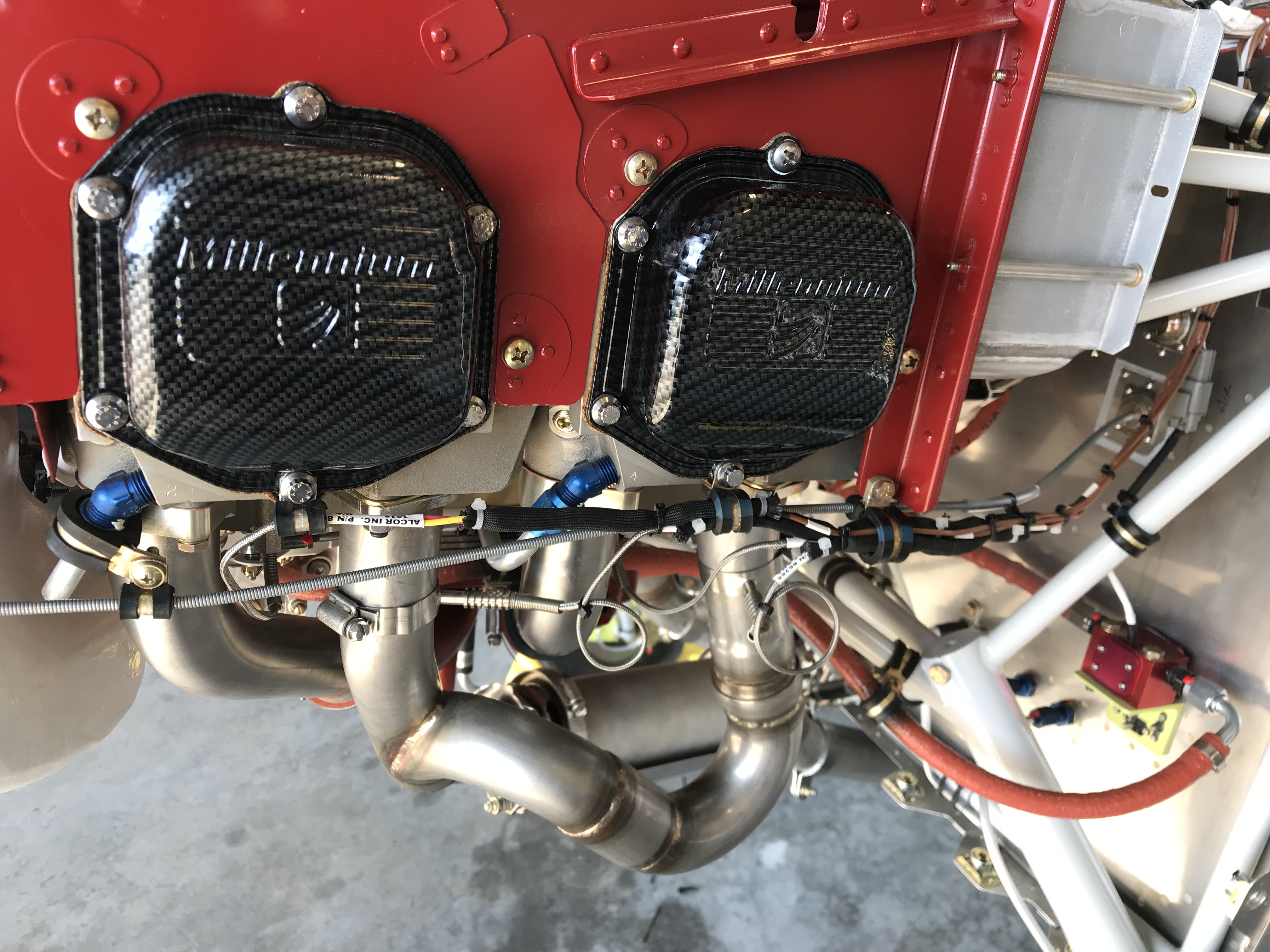
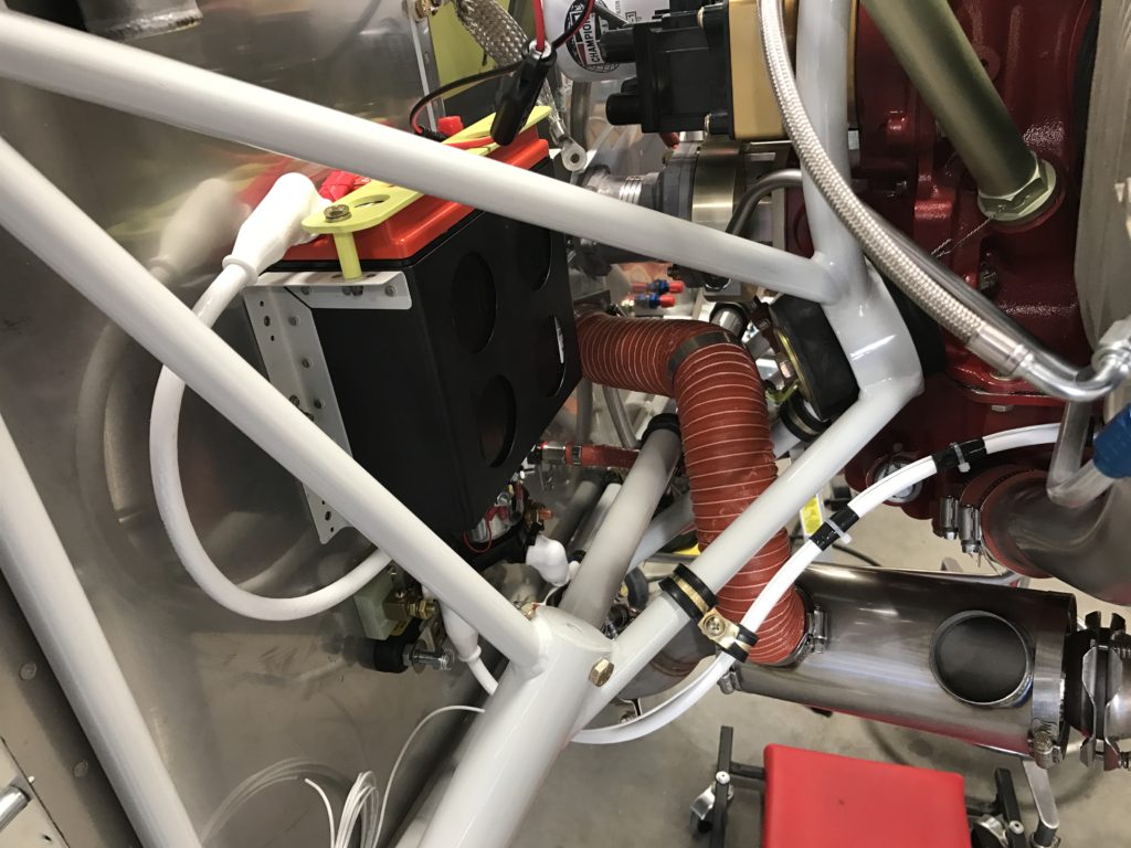
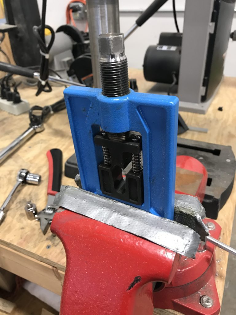
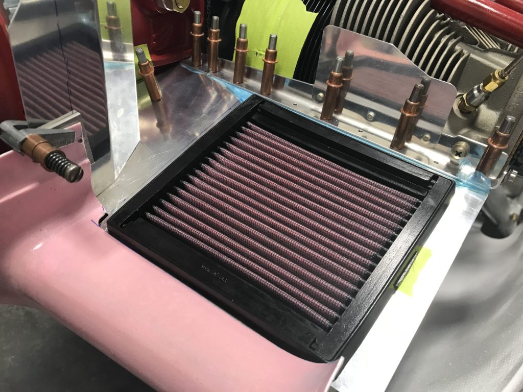
 After that relaxing little gusset diversion, I was ready to hit the snorkel-fitting process again. Here’s the final result – flanges with platenuts that hold the snorkel to the left air ramp assembly and also support the outer edges of the rubber air filter flange.
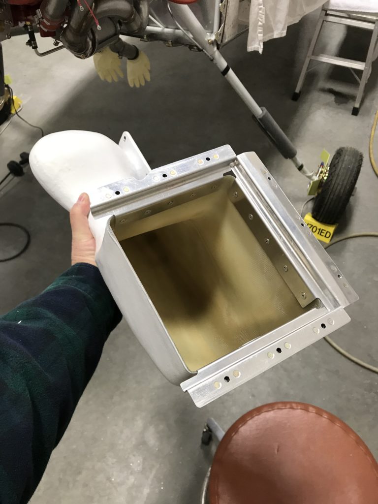
The instructions with Van’s “Filtered Air Box” kit are lacking in detail, so take them as advisory; what you’ll want to have at the end are three flanges that look more or less like what I have here. The rough drawings of these flanges in the instructions don’t really match what you’ll be able to do with the parts provided in the kit. Once again, you just gotta make ’em work.
One additional note – the instructions give you a method to final-trim the snorkel’s upper opening to accommodate the flanges. I had to do some trim-fit-repeat loops to make sure the flanges weren’t pushing the air ramp up and changing its fit to the cowl. I’d recommend not drilling the side flanges to the snorkel til you’re satisfied with the fit.
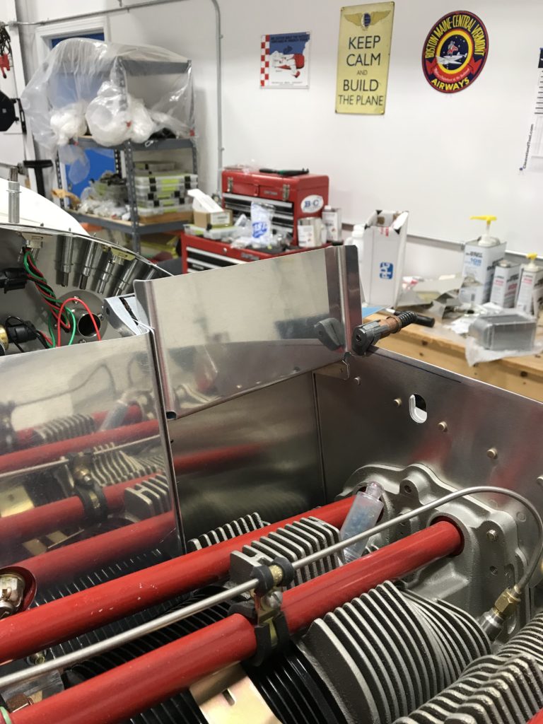
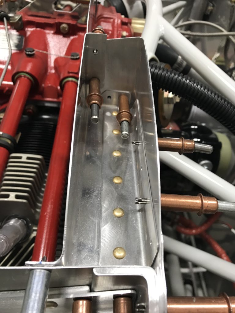
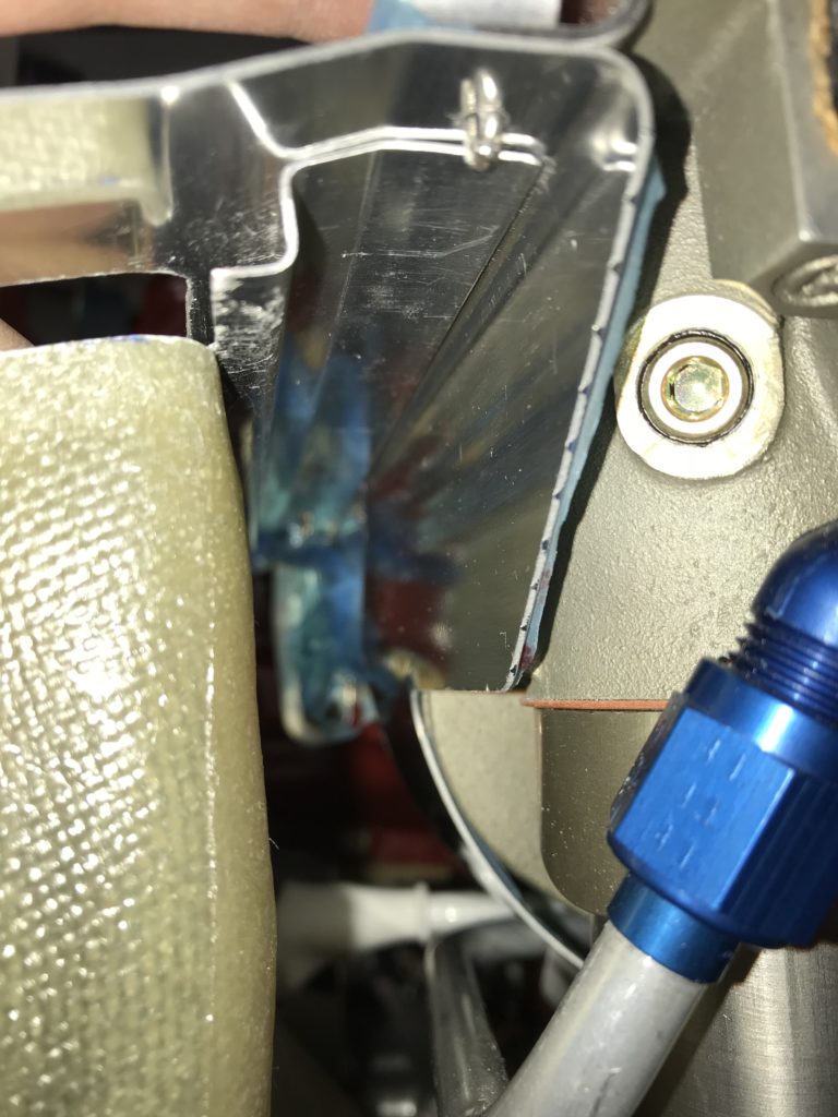 The instructions say that it may be necessary to adjust the bend on the rear mounting flanges. Well, it’s necessary and you’ll have to make a second bend in the flange’s upper surface so that it conforms to the left air ramp as shown in the picture above.
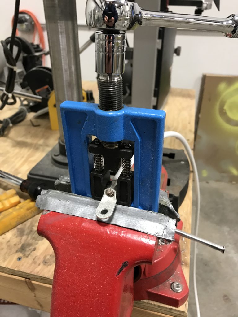
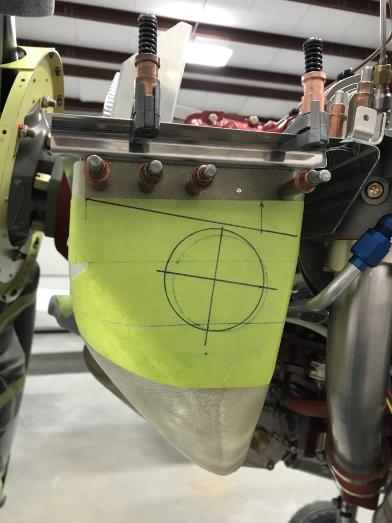 Once the flanges were fitted and drilled to the snorkel, I laid out the alternate air door hole. This accommodates the door’s flange which is riveted to the snorkel. As you can see, the mounting axes of the hole are at an angle so that when the the flange is drilled it’s at the right orientation to accommodate an actuator cable which will be installed later.
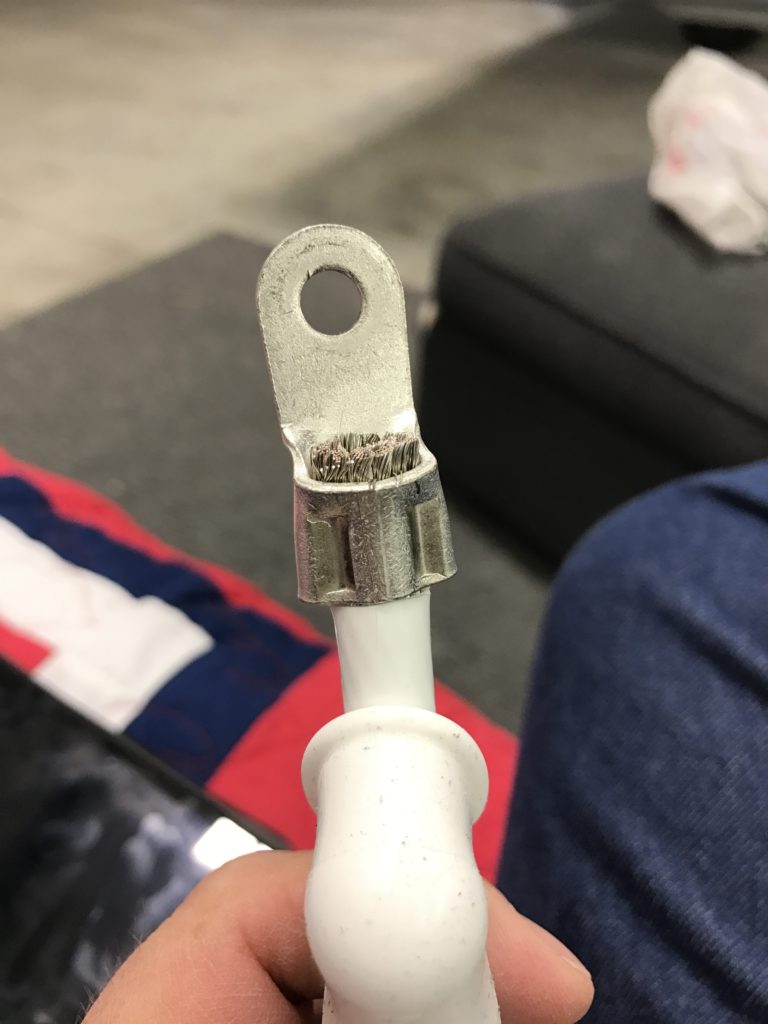
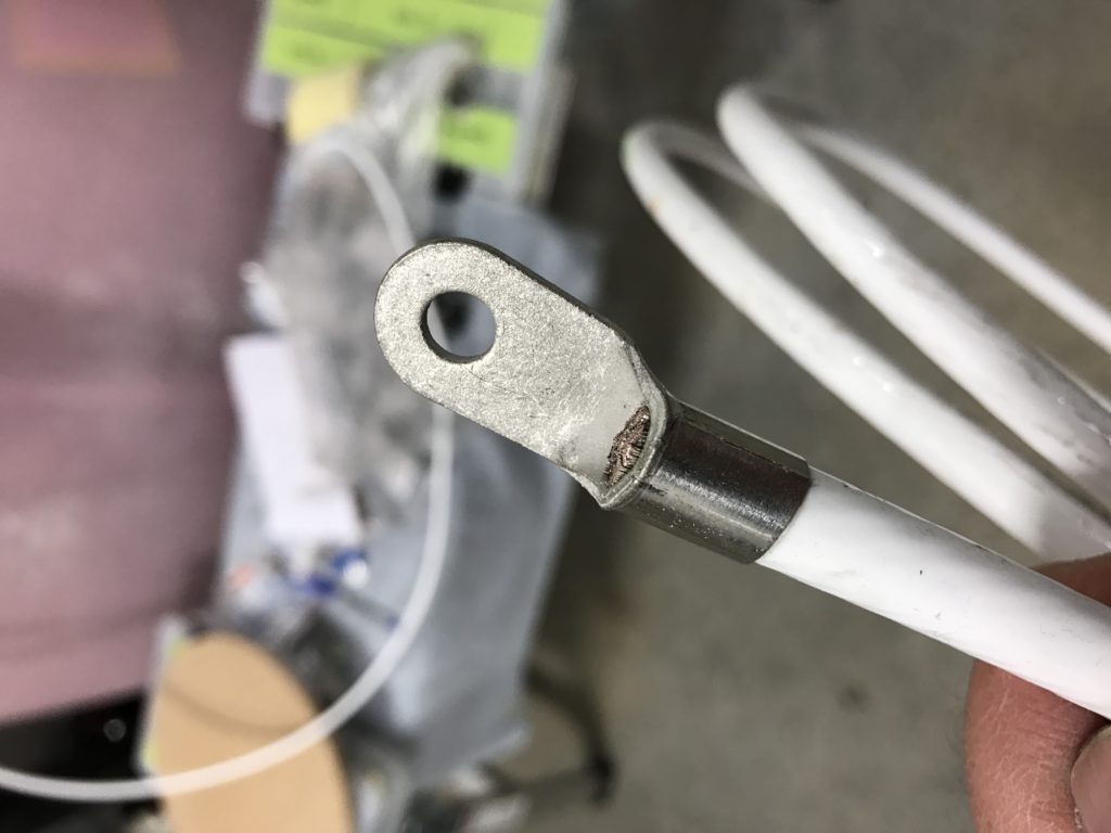
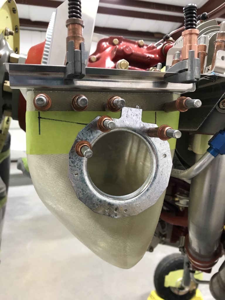 Here’s the flange drilled to the snorkel. Later I made up some epoxy-flax paste to fair around the flange edges and then riveted the flange into place.
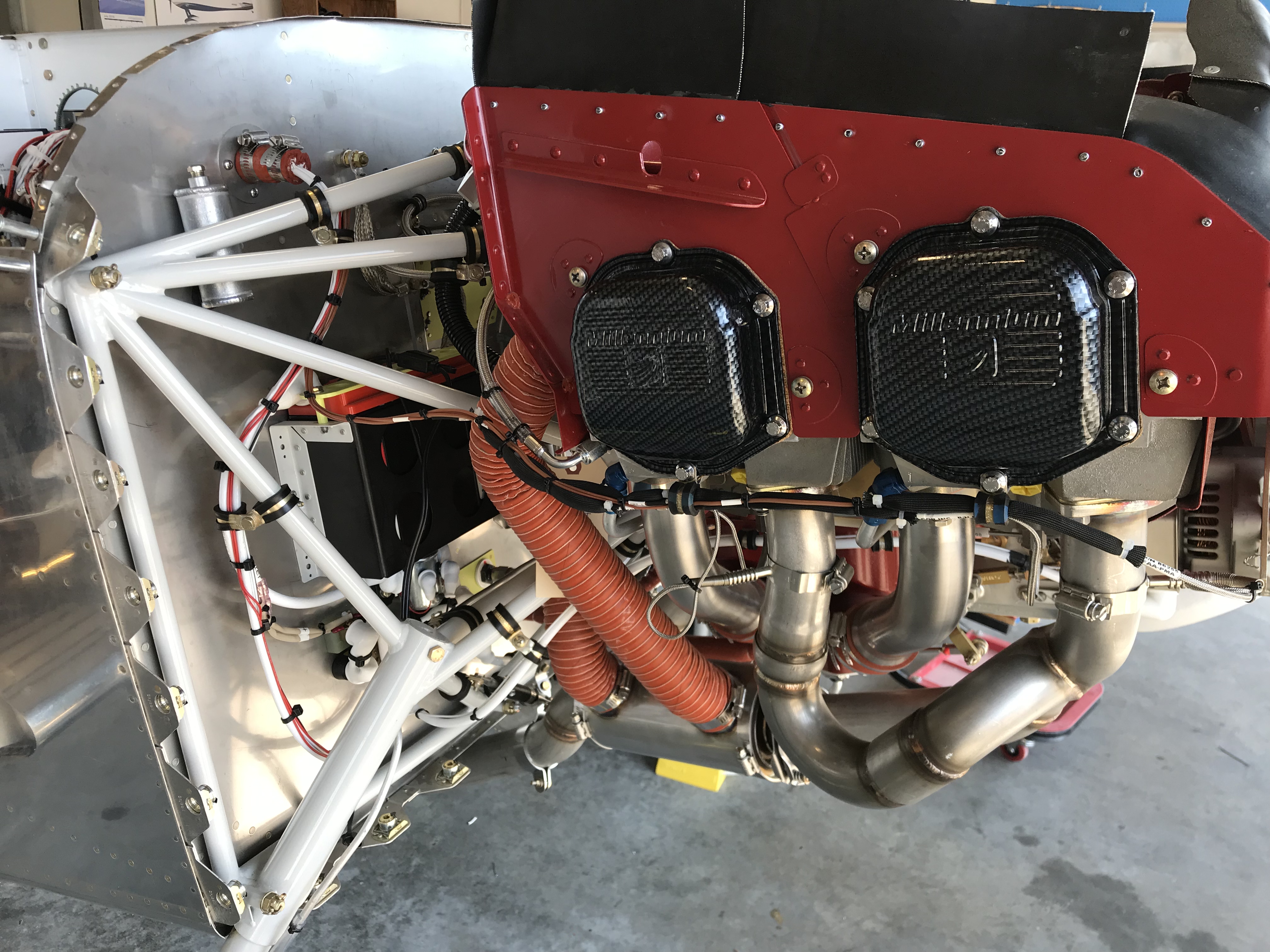
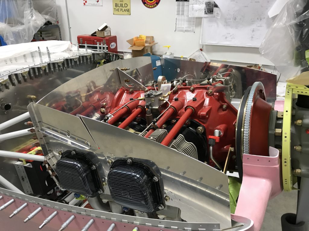
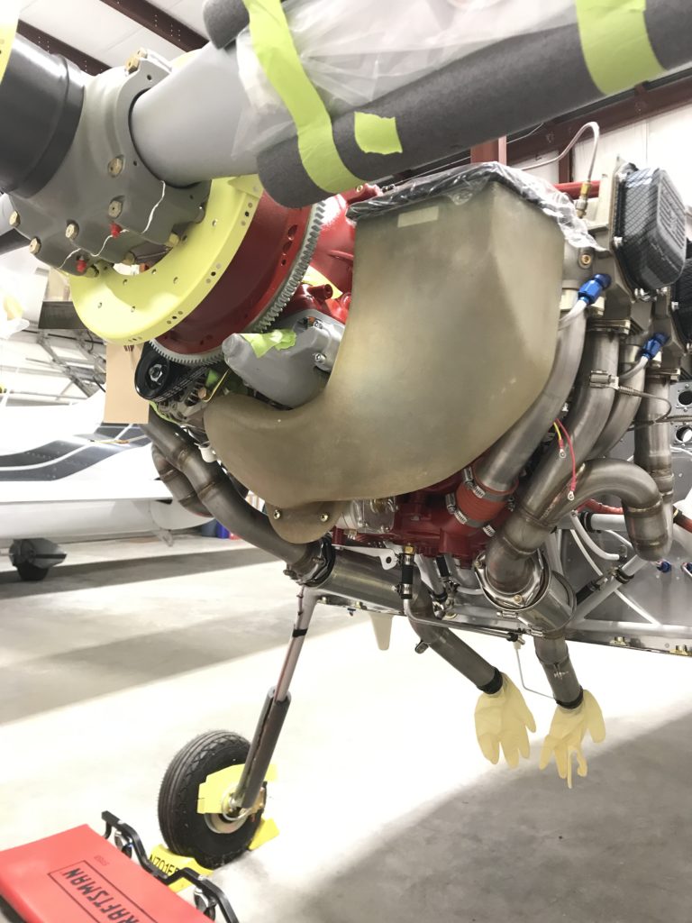
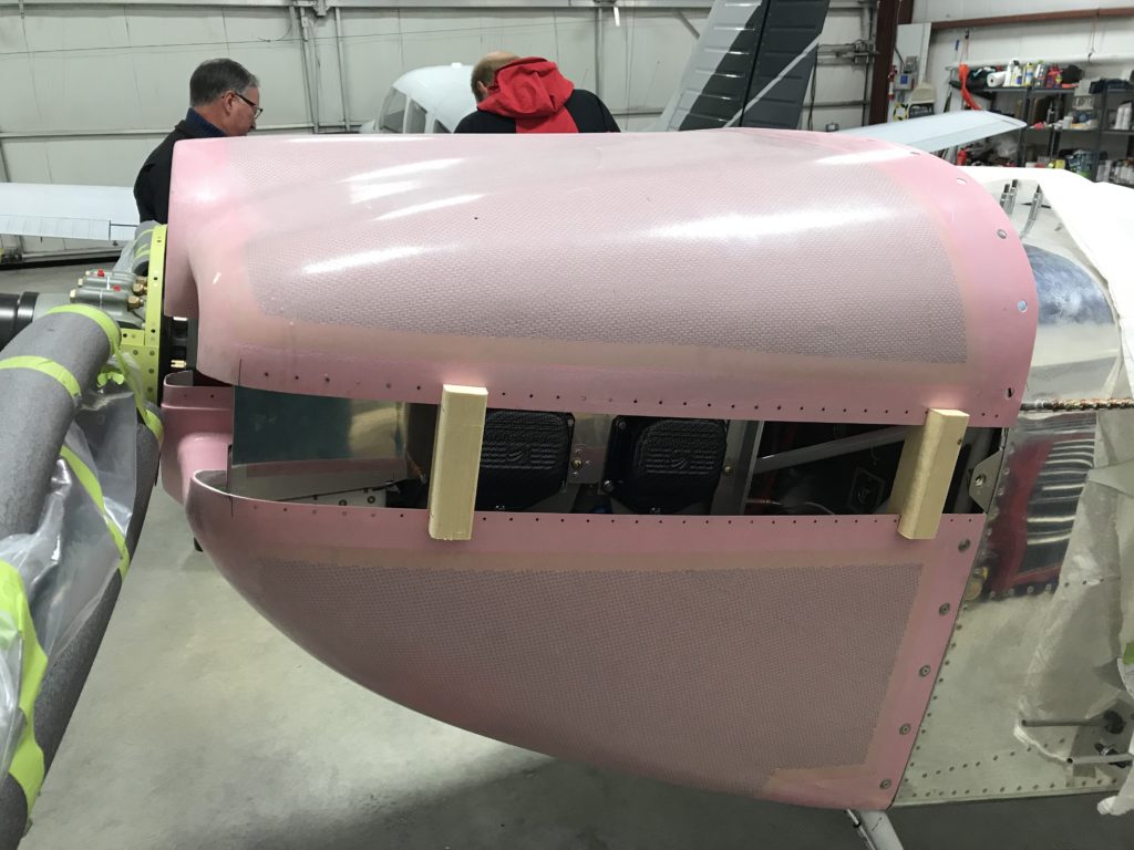
 At this point the baffles, snorkel and filter are starting to look pretty good!
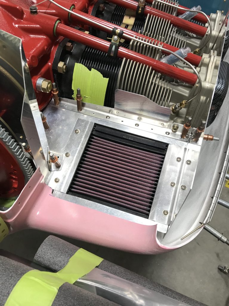
In this pic I’ve fabricated the hold-down brackets which keep the filter in place; the left and right brackets are installed and there’s another one that will go across the back. You can see that the outboard bracket is actually an angle that abuts the CB-1003 cylinder baffle; I had just enough material on the -1002A ramp to accommodate the snorkel flange and bracket, which is why I recommend not trimming the ramp until you’re ready to lay out holes for the screws you see in this picture.
Whew…that was a lot of work. You’re seeing this in one post, but at this point I’m almost three months into the baffle-fitting process; we’re moving again so I haven’t had as much time as I’d like to devote to the project.
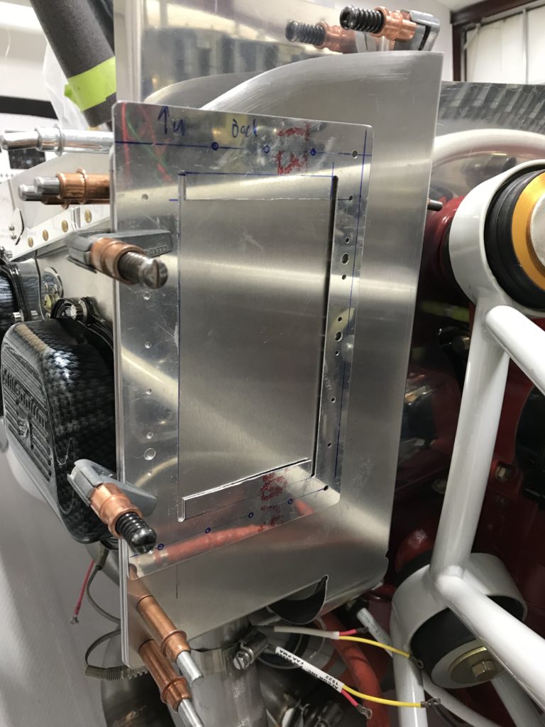
At this point, it’s time to trim the baffle upper edges to conform to the upper cowl (astute readers will note that there’s no post for the cowl yet – that’s on the way when the baffles are finished). I adopted Bruce Hill’s method of laying out the cut lines, which he’s documented on his website. I won’t repeat his instructions here.
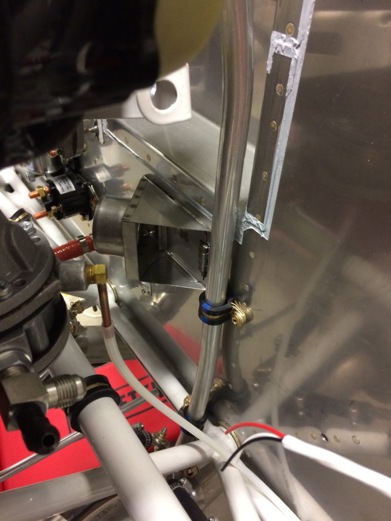
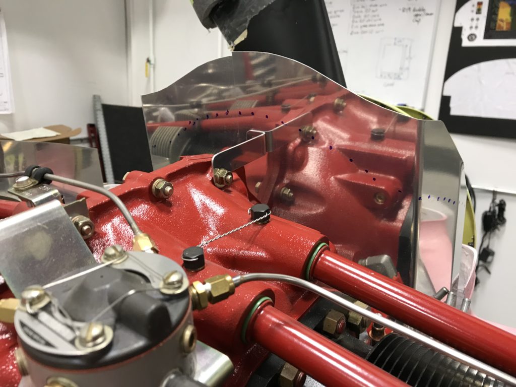
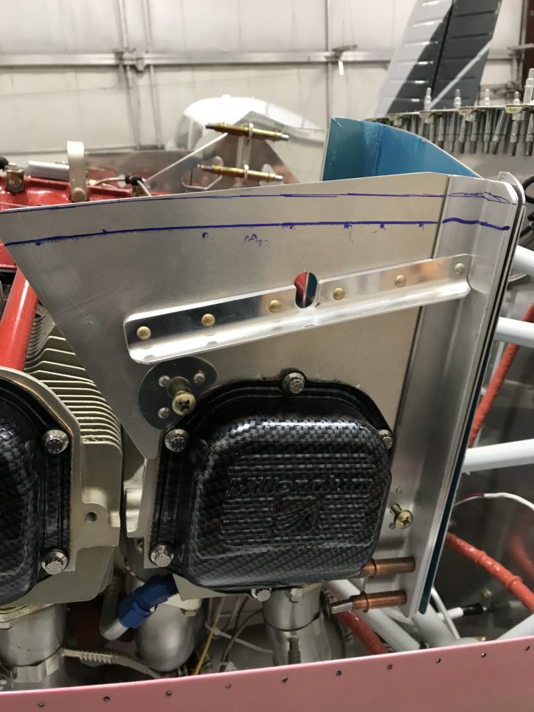 In this pic the heavy blue sharpie line is the reference line laid out using Bruce’s method; it should provide a 1/2″ gap between the baffle and cowl. But this process is kinda wiggly so I’ve marked a thin blue line 1/4″ above the reference line for the initial cut. I pulled all the baffles off the airplane and rough-trimmed to that line.
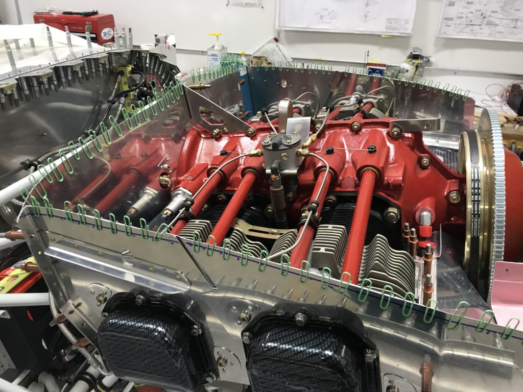
The time-honored process used to mark the final trim line, used by RV builders for decades, is to use paper clips as a cheap way to measure the cowl-to-baffle gap after trimming the baffle edges. Put the clips on the baffle edges, lay the upper cowl in place and gently push it (and the paper clips) down, then remove it. After that it’s simply a matter of measuring down from the upper ends of the clips to set whatever gap you want – in my case, I went for the minimum 3/8″ gap recommended by Van’s just to reduce the chance of any air leaks later on.
In the picture above I’ve made the first cut and have placed almost 100 paper clips on the baffles and am about to cleco the top cowl in place. I don’t have any pics of the process, but after repeating the paper-clip measurement loop twice I had what I think is a nice gap along the side and rear baffles.
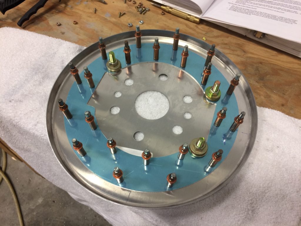
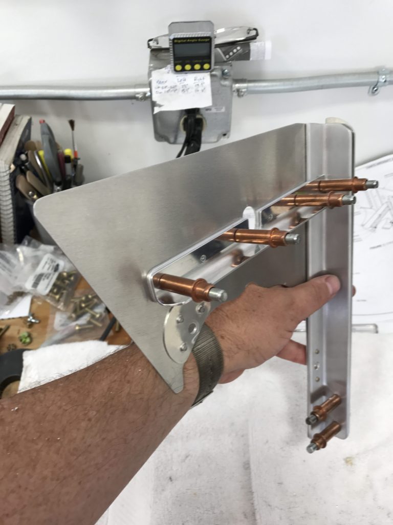
 As I mentioned before, one of the few weak parts of the baffle kit is Van’s design for the oil cooler mount. The pic above is the Van’s-supplied oil cooler brace being fitted to the baffles.
 Adding the heavy support angle I mentioned earlier made it necessary to modify Van’s oil cooler bracket to provide a little more space on its outboard edge, otherwise the bracket’s rivet and bolt holes would be too close for comfort to the angle web. I couldn’t really make the kit-supplied bracket fit to my satisfaction, so I made another one from scratch and used the original as a template to match-drill holes for rivets and oil cooler mounting bolts.
I played with the location of this bracket a bit, trying to get it as high on the baffle as possible to maximize cooling flow while providing sufficient edge distance for the rivets that hold the whole thing together.
Here’s the final opening. As you can see, I was able to keep a fair bit of the mounting hole above the cylinder. Cooler oil temps = happy engine on hot days.
Here ‘ve rough-trimmed the brace to accommodate another round of paper-clip gap measurement, and I’ve also match-drilled it to the cooler mounting bracket and support flange. You’ll see that I’ve also laid out and drilled holes for the ignition harness gasket (the figure-eight shaped hole in the center of the picture).
As delivered by Van’s, the oil cooler brace’s rear mounting flange angles down, which takes away valuable space on the rear baffle that could be used to move the oil cooler higher. Taking a cue again from Bruce Hill, I cut off the original flange and used some spare angle stock to fabricate a replacement on the brace’s upper side which picks up rivets on the mounting bracket upper edge.
 Here’s the brace trimmed and ready for riveting. When I install the oil cooler there will be an additional stainless steel brace that attaches to the #4 cylinder’s upper valve cover screw hole and one of the inboard oil filter bolts. This should provide some additional resistance to fatigue cracking of the baffle.
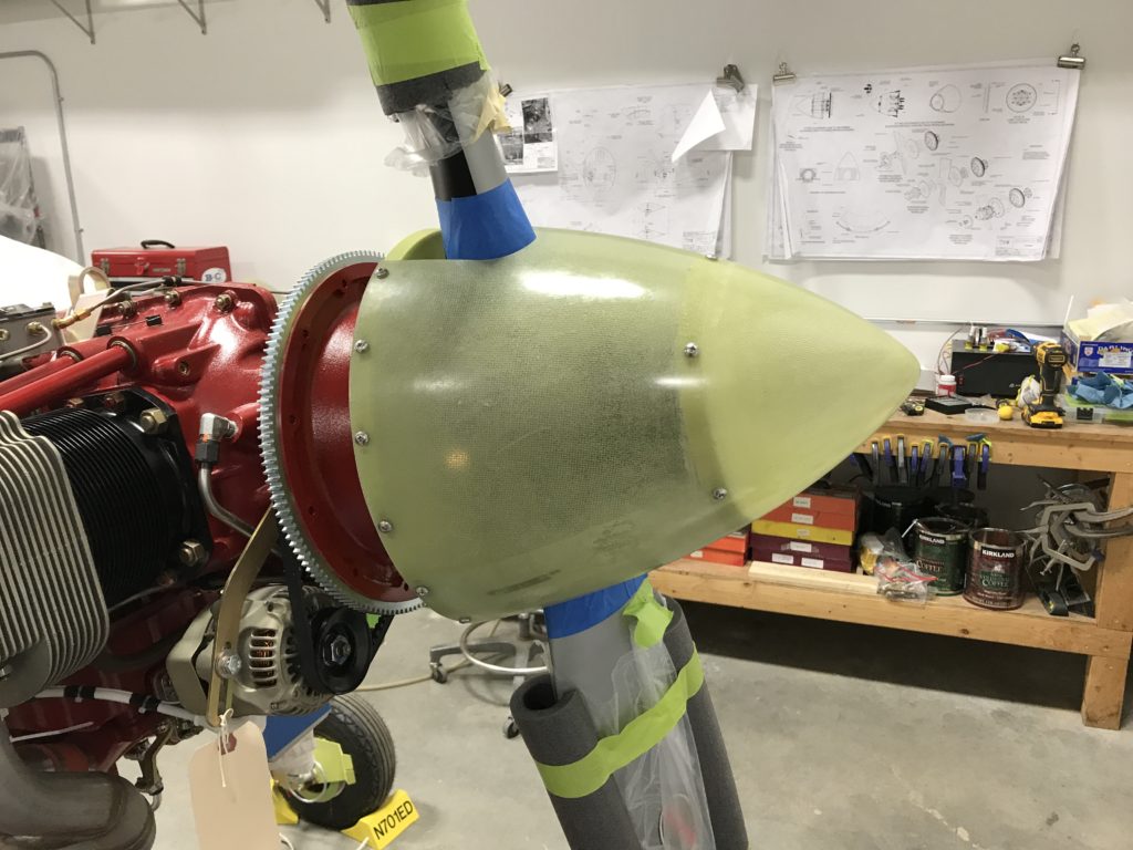
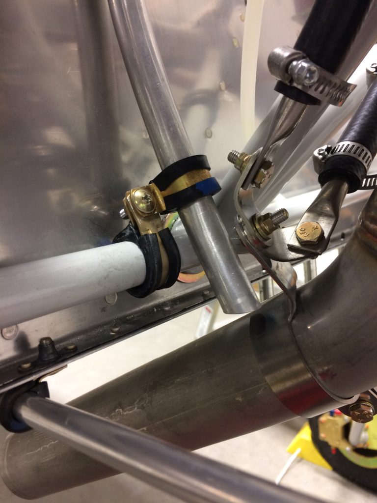
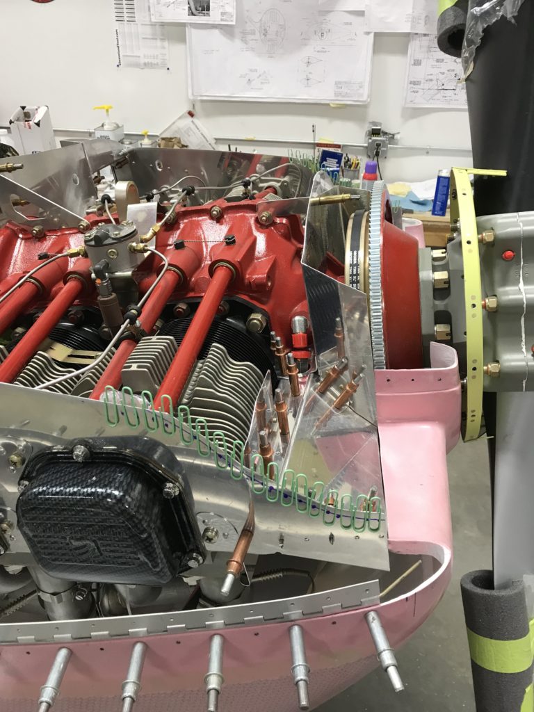
 Just when it seems the baffles are in the outbox, there’s more fitting and trimming to be done. I had previously fitted the front baffles – they surround the crankshaft – to the air ramps, but they must be fitted to the cowl in the same fashion as the side and rear baffles. If you look closely you can see blue sharpie dots where I’ve marked out initial reference lines as I did for the other baffles. A couple of measure-trim-fit-repeat cycles got them fitted to the basic curvature of the upper cowl.
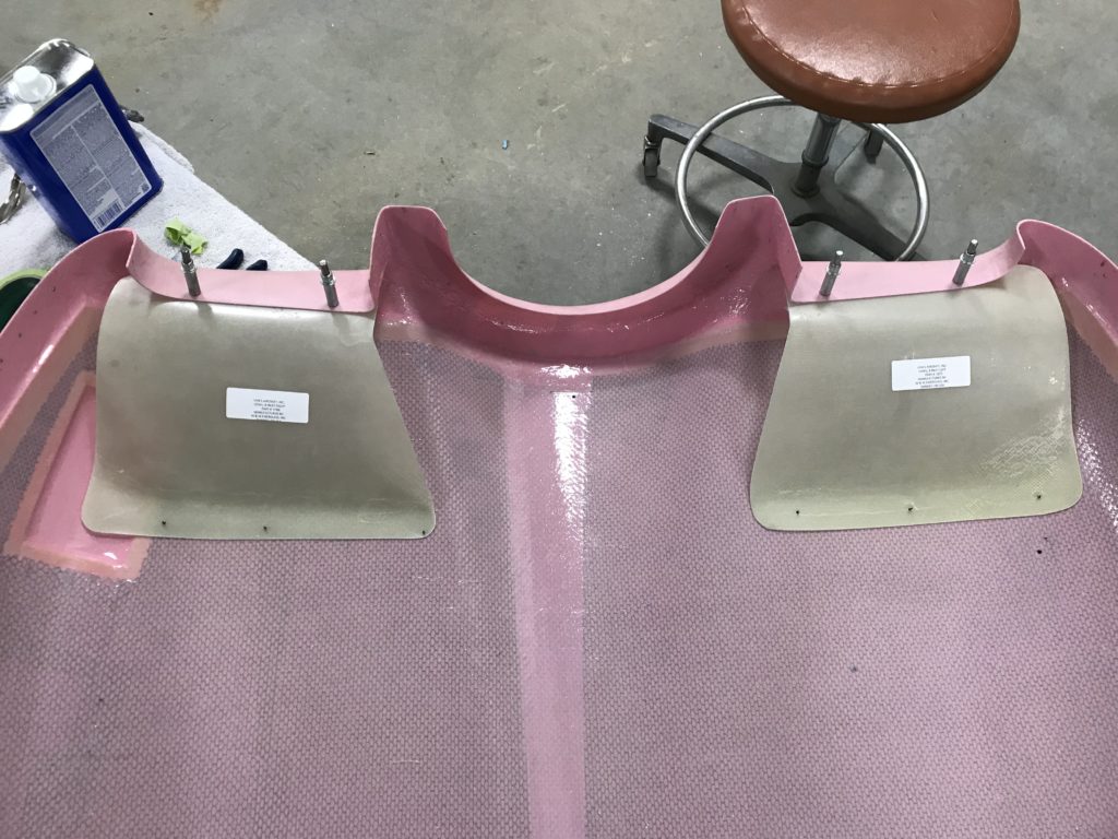
But there’s a complication. These fiberglass ramps must be fiberglassed into the upper cowl to smooth cooling airflow into the engine compartment and as is often the case for Van’s, the instructions don’t say much about how they fit. In this case, the ramps will affect the fit of side baffles for cylinders #1 and #3, so they should be in place so those baffles can be trimmed to fit.
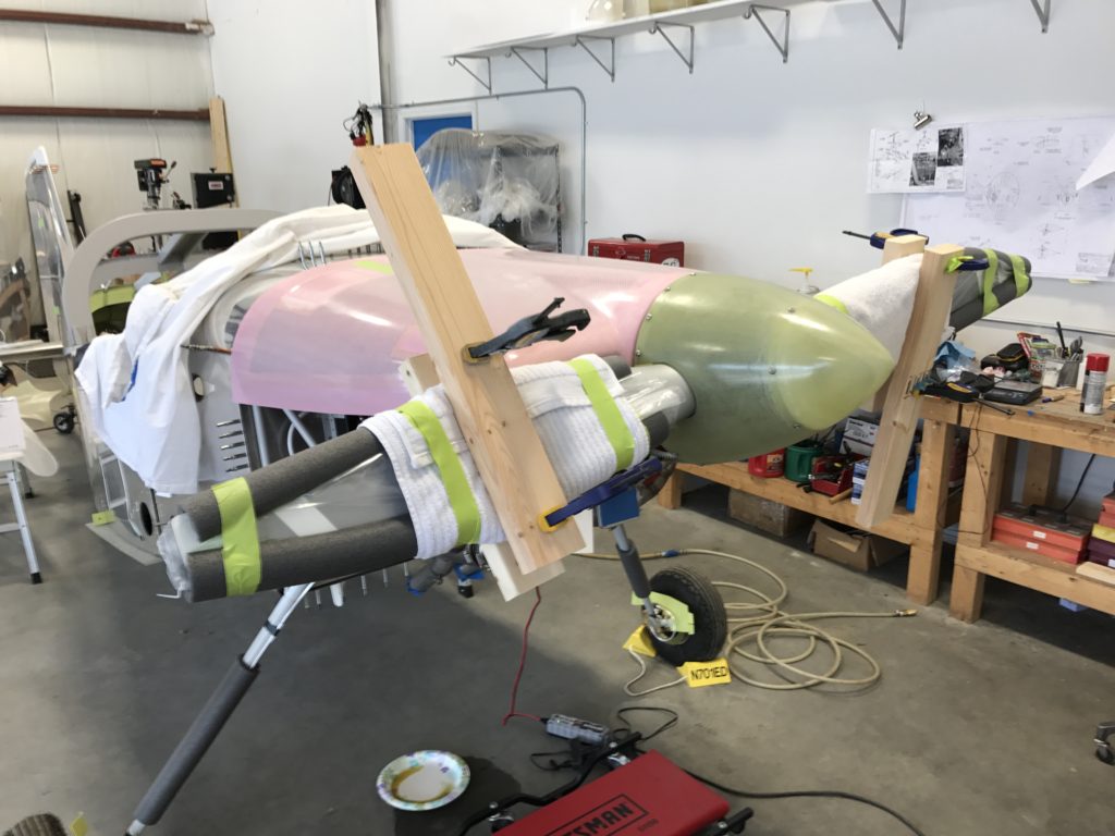
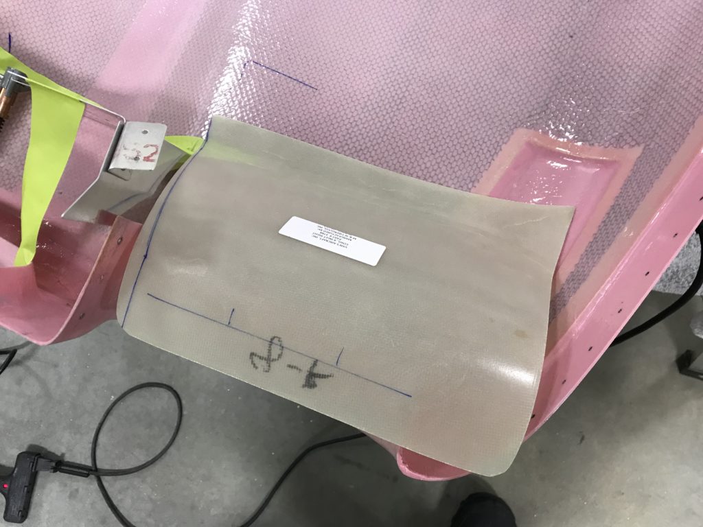
The ramps must attach to the cowl inlet and upper surface and also have a gap between their inboard edges and the center baffles. Here I’ve removed the baffles from the engine and taped them in place to get an idea of how much to trim the inboard edges of each ramp.
I tend to overthink issues like these, but in this case I just roughed out cuts on the inboard ramp edges to accommodate the center baffles, slid the ramps til they felt about right on the cowl, then drilled them into place. The cleco holes will be filled later with epoxy/flox. The left ramp (right side in this picture) didn’t fit too well along its aft edge but a little reshaping, helped by my heat gun, took care of that nicely.
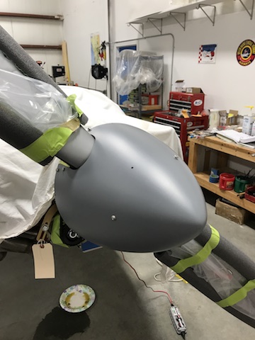
 Ok, I think this really is the last bit of baffle fitting that needs to be done. I broke out the wooden blocks and paperclips – a couple of passes and I was done.
More to follow as I rivet the baffles together then paint and install them.