Back to the wings

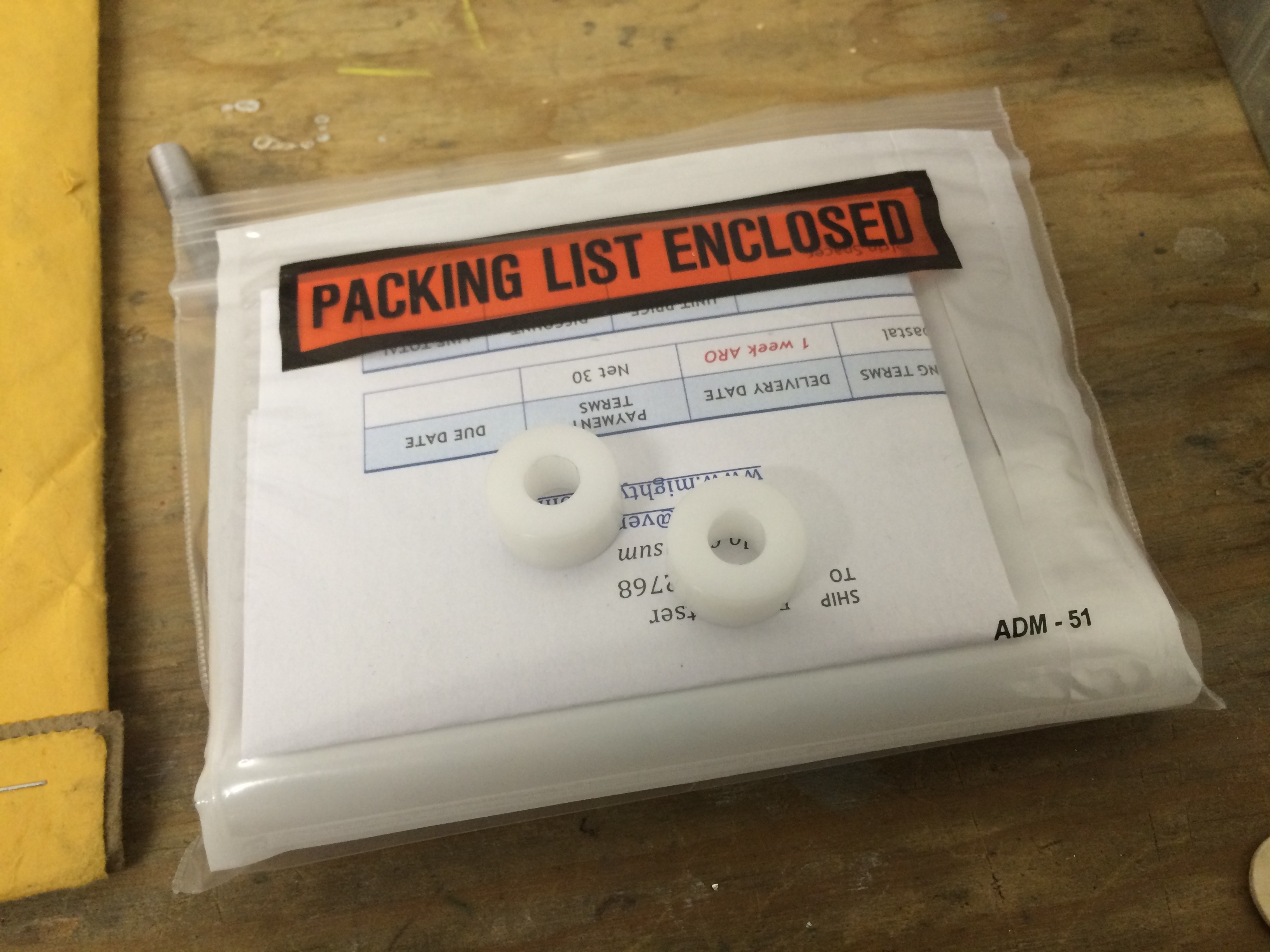
I’m working on preparing the wings for final installation, and one task that’s easier to perform now is installation of the Garmin GSA-28 autopilot roll servo. Nothing too tricky here, the G3x installation manual covers the process nicely. I’ve had this servo sitting around for a couple of years and it took a bit of searching to find the necessary parts.

Roll servo mostly installed
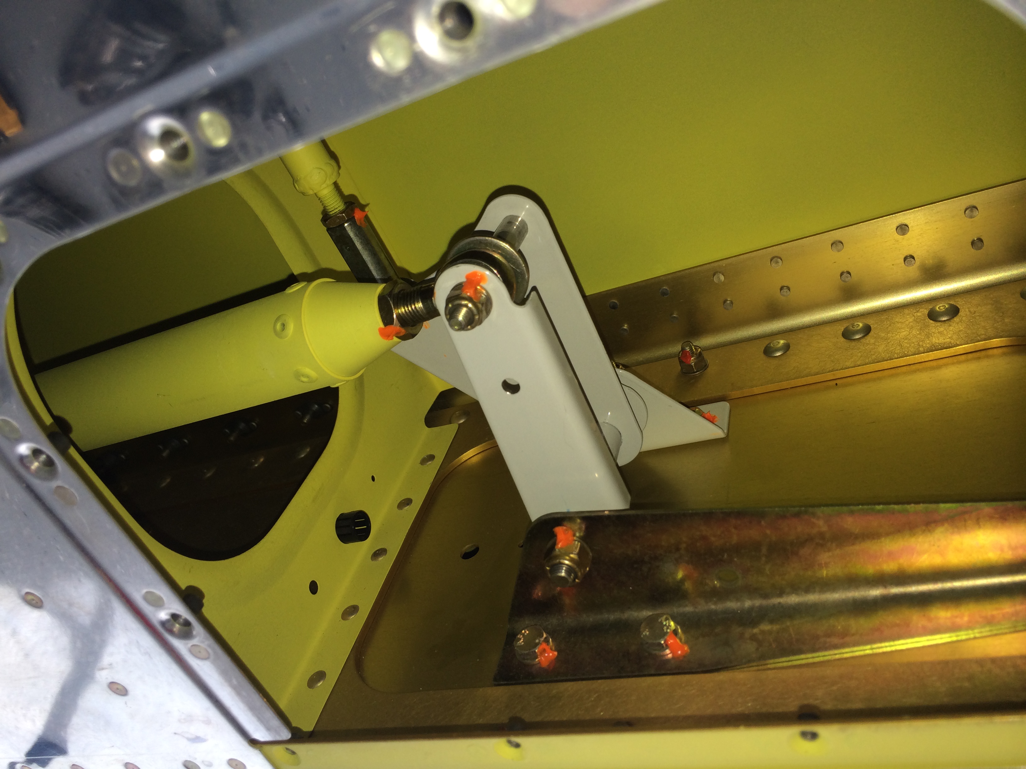
One gotcha…in the past, Garmin claimed that their servo was compatible with mounting brackets from other manufacturers but that turned out not to be the case. I had originally installed an Advanced/Dynon servo bracket, because way back when I built the wings I was planning to use their avionics.

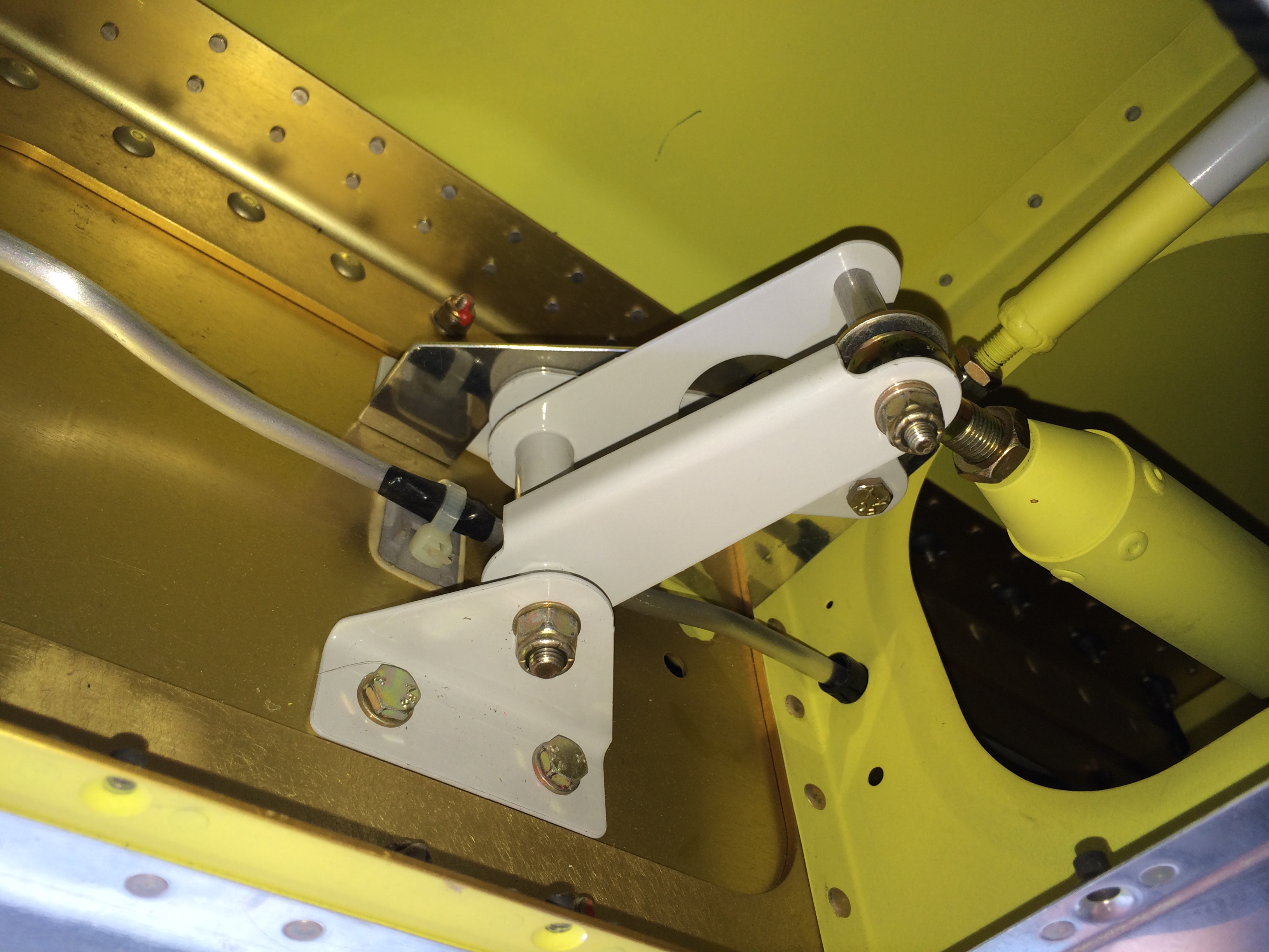
Turns out that the Garmin servo *isn’t* compatible with Dynon’s brackets, so I had to swap it for the one from the GSA-28 install kit. This won’t be a big deal for anyone who’s installing a servo from scratch, but if you’re swapping from another manufacturer, be prepared for a little extra work.

Trimming the starboard stabilizing ailertooters

I have an unfortunate tendency to communicate in movie quotes, so bonus points to you if you can identify the “starboard stabilizing ailertooter” reference without using Google, Bing or some other internet search megalith.

No, the Mighty RV doesn’t have ailertooters but it does have ailerons and that’s what prompted the title. One of the last bits of cockpit work is installing the aileron trim motor; I fitted the bracket way back when I was building the fuselage center section and all that was left was to install the motor and connect it to the flight controls.

Aileron trim installed

I didn’t take any in-process pictures, so all you get to see is the final product. The trim motor is under the square white bracket in the lower center of this picture. It drives a lever that’s connected to the control sticks with springs which are adjusted to be in just enough tension that the motor can move the sticks but not significantly affect roll control feel.

A minor modification

One leftover task from fitting the wings was installing the control stops that limit aileron travel. The plans call for riveting aluminum blocks to the inboard aileron hinge brackets on each wing, and these blocks serve as stops hitting against the steel hinge points bolted to each aileron.

But other builders have a more elegant solution. Turns out a small Delrin spacer, fitted where an aluminum spacer normally goes on those steel hinge points, make a perfect control stop. All that’s needed is some Delrin rod stock of the appropriate diameter, cut to the appropriate width, with a 5/16″ hole drilled in the center to accommodate an aluminum bushing to protect the spacer from wear. When the aileron is at its maximum up travel, the Delrin spacer hits against the top of the aileron hinge bracket.

To me this is a much better solution than having the steel hinge point banging against an aluminum block. Some trial and error is required to find the right spacer diameter – the larger the spacer diameter, the smaller the aileron travel – but checking out other builders’ websites who’ve done this, 3/4″ seems to be a common diameter and that size worked for me as well.

Aileron control stopsBecause I’m an obsessive-compulsive engineer, the spacers had to be precise. As I am wont to do, I threw money at the problem and had a local machine shop bore the holes in the middle of each spacer.  Joe at Coastal Milling Works in Medford MA is happy to take on small milling and machining jobs for a very reasonable cost. After spending too much time trying to center-drill some test spacers, I decided to hand the job to Joe and he handed me back ten perfectly-drilled spacers. If you’re in the Boston area and need some small machining work done for your project, go to Coastal – you’ll be glad you did.

Spacer assembledHere’s the finished spacer, and it’ll go just to the left of the rod-end bearing and washer in the picture above. This little diversion came out very well…much better than the plans aileron stops.

I have a few extra spacers…if you’re contemplating this approach and are interested, let me know.

Rigging the ailerons

Next up on the list of things to be done is rigging the ailerons and aileron pushrods to the control sticks. There’s nothing too difficult here, but like a lot of other tasks at this stage, there’s a lot of tweaking and adjusting involved.

There are two pushrods for each aileron, one from the control stick to a bellcrank in the wing, and another from the bellcrank to the aileron itself. I had already adjusted both bellcrank-to-aileron pushrods when I built the wings, but I wanted to recheck them anyway. So I dug out the bellcrank jig and the fixtures I made to hold the ailerons in trail.

Here’s the fixture that establishes where the trailing edge of the aileron should be…it’s bolted to two tooling holes in the outboard wing rib –

2014-08-10 12.24.56

And here’s a couple of pieces of wood I screwed together to hold the aileron itself in place on the fixture. You can see the two lines that define where the trailing edge should be…

2014-08-10 12.24.46Since I already had a pretty good idea that the outboard pushrods were correctly set, I just slipped the bellcrank alignment jig into place and verified that everything was still ok.

Bellcrank jig in placeYou can’t see the bellcrank jig very well, but it’s the silver piece of metal above the bellcrank itself. It’s placed over a pushrod bolt, and if the jig’s forward edge rests flush against the spar *and* the aileron is aligned in trail, everything is set – which it is here and in the opposite wing.

Torqued bellcrankWith the ailerons properly in trail, I clamped the control sticks in place so they were vertical (sorry, no pictures) and adjusted the long bellcrank-to-stick pushrods to the proper length. I then went back and torqued all the bellcrank bolts and nuts, as you can see from all the Torque-Seal in the picture.

It was kinda neat to move the control sticks and see the ailerons move…before the wings come off again I may have to throw a seat in the cockpit and play pilot for a little while!

Declaring the ailerons complete

I spent most of my shop time during the last week installing the left aileron’s brackets , and getting both ailerons correctly fitted on the wing hinge brackets. As other builders have also experienced, the aileron hinge brackets on my wings had a slight list and I was concerned that this might interfere with aileron movement. But I was able to adjust the inboard/outboard position of the ailerons by adjusting spacers and washers on the aileron hinges – so there was no problem. Very cool!

Ailerons complete!

With that, I’m declaring the ailerons complete – for now.

Flat surface

The last major hurdle in the never-ending aileron saga was to put the left aileron on a flat surface, pull the blind rivets that secure the spar bottom and skins, and squeeze the end rib rivets. When I did this before I used an old hollow-core door, tweaked it with shims until it was flat, then laid the aileron on it and weighted it down with two heavy pieces of MDF. Worked ok, but it was a little too wiggly for my taste. But where else would I find a flat surface?

Well, it turns out that we just finished having our kitchen remodeled, and those new granite countertops looked like they would fill the bill. So I pulled out the trusty SmartLevel, checked ’em, and sure enough they were flat to within 0.1 degrees in all directions. For $8,000, they damn well ought to be.

So after breakfast today I cleaned all the kitchen crap off of those countertops and turned ’em into my temporary workbench. I plopped that aileron on the bar countertop, weighted it down, ran an air hose up the stairs from the garage through the den to the kitchen, grabbed my pop-riveting tool and pneumatic squeezer, and went to work.

Dave's $8,000 workbench

Man, those countertops worked like a champ – that aileron came out with no more than 0.1 degree of twist. I did as many rivets as I could up there – enough to lock the structure in place – then finished everything else up downstairs in the shop.

Back from another trip

Just got back from another trip yesterday. Got to work this morning riveting the upper spar to the nose and main aileron skins. Managed to do it myself this time, after good practice on the flaps. Came out well, I’m pretty psyched. Once that was done, I squeezed all the nose rib rivets I could reach.

A lot done

Got the aileron nose ribs, spars, reinforcement plates, platenuts and counterweight all riveted together today. Also clecoed the entire aileron assembly together in preparation for riveting, and mounted it in the 2″x4″ uprights I used previously to hold the aileron.

Al Jazeera aileron counterweight

The only remaining tasks before final assembly were to match-drill, countersink and prime the counterweight pipe, and assemble the spar/counterweight structure. You’ll find the details on this process in the previous entries on this page, so I’m not gonna repeat them here.

I was a little surprised to see the following text on the replacement counterweight pipe that Van’s delivered…click here for the full-size picture. Be patient, the original pic is 1+ megaabytes.

Al Jazeera aileron counterweight

Dusted off all those left aileron parts

With the with flaps done, I dusted off all those left aileron parts and jumped back into finishing it up. First order of business was to do the final bend on the trailing edge. I used the bending brake I had made previously, but wasn’t getting that nice 3/16″ radius called for in the plans.

So I started experimenting with my hand seamer (no jokes, please). Some other builders have used them to do the final trailing edge bend, but I was wary about the seamer edges putting crimps in the aileron skin. So I hit on the idea of taping strips of 0.025″ alclad to the seamer’s jaws to distributed the seamer’s clamping force a little more evenly.

Modified hand seamer

That worked like a champ, and with the dowels still taped in place, I was able to get the bend radius right where I wanted it.

Bent left aileron