A happy New Years at the ThermosWorks

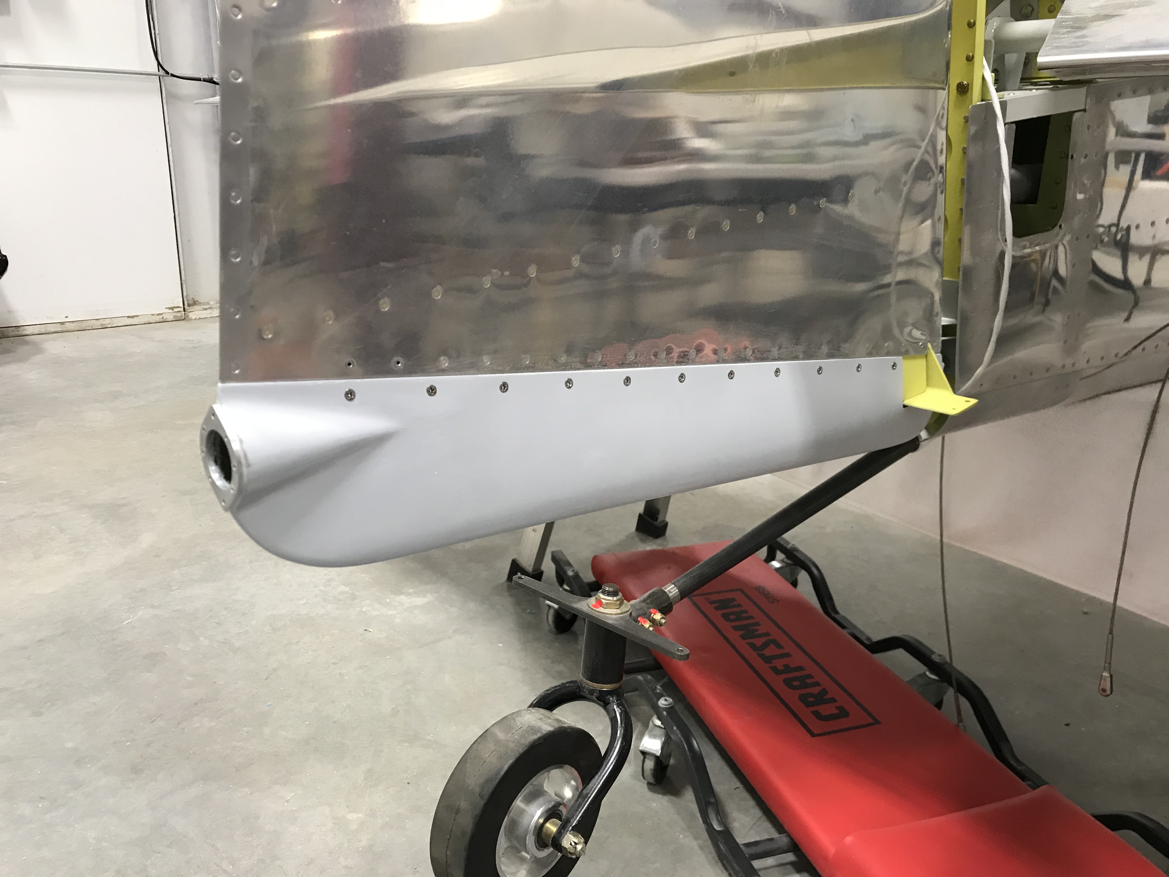
After more than 12 years, the rudder and elevators are mounted to the empennage and they’re moving freely without binding. Took a lot of fiddling with washers and spacers, and some expert help from my Tech Counselor (thanks Bob!) to make that happen, but it’s done.

Here’s a short demo of today’s work…

More fiberglass work on the tail

Just when I thought I was done with fiberglass work on the empennage, a problem with the tail strobe/nav light proved me wrong.

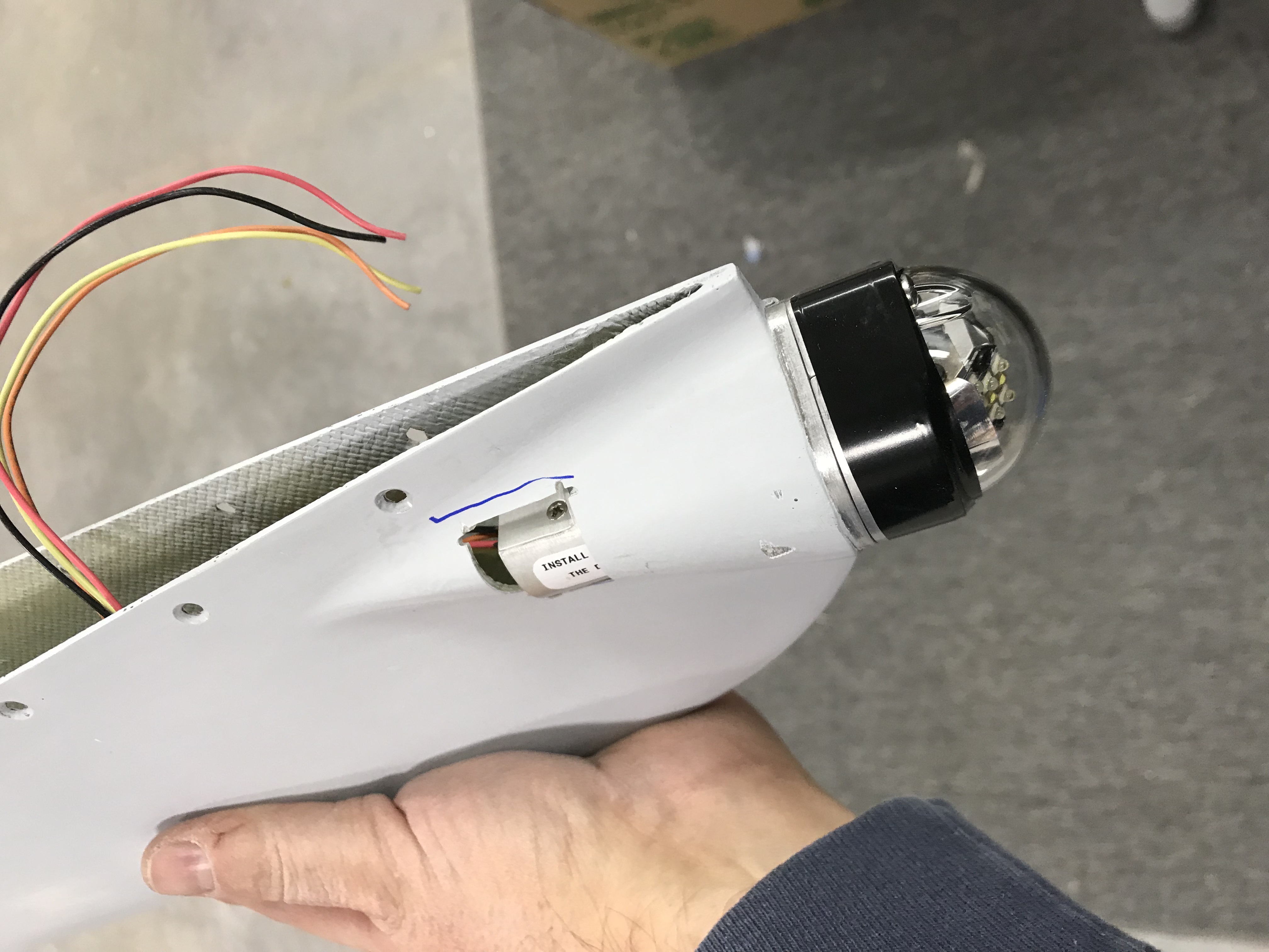
I’m using Whelen’s LED nav lights and the tail light is just a little wider than the lower rudder cap can accommodate. Time to get out the Dremel saw and do some surgery…

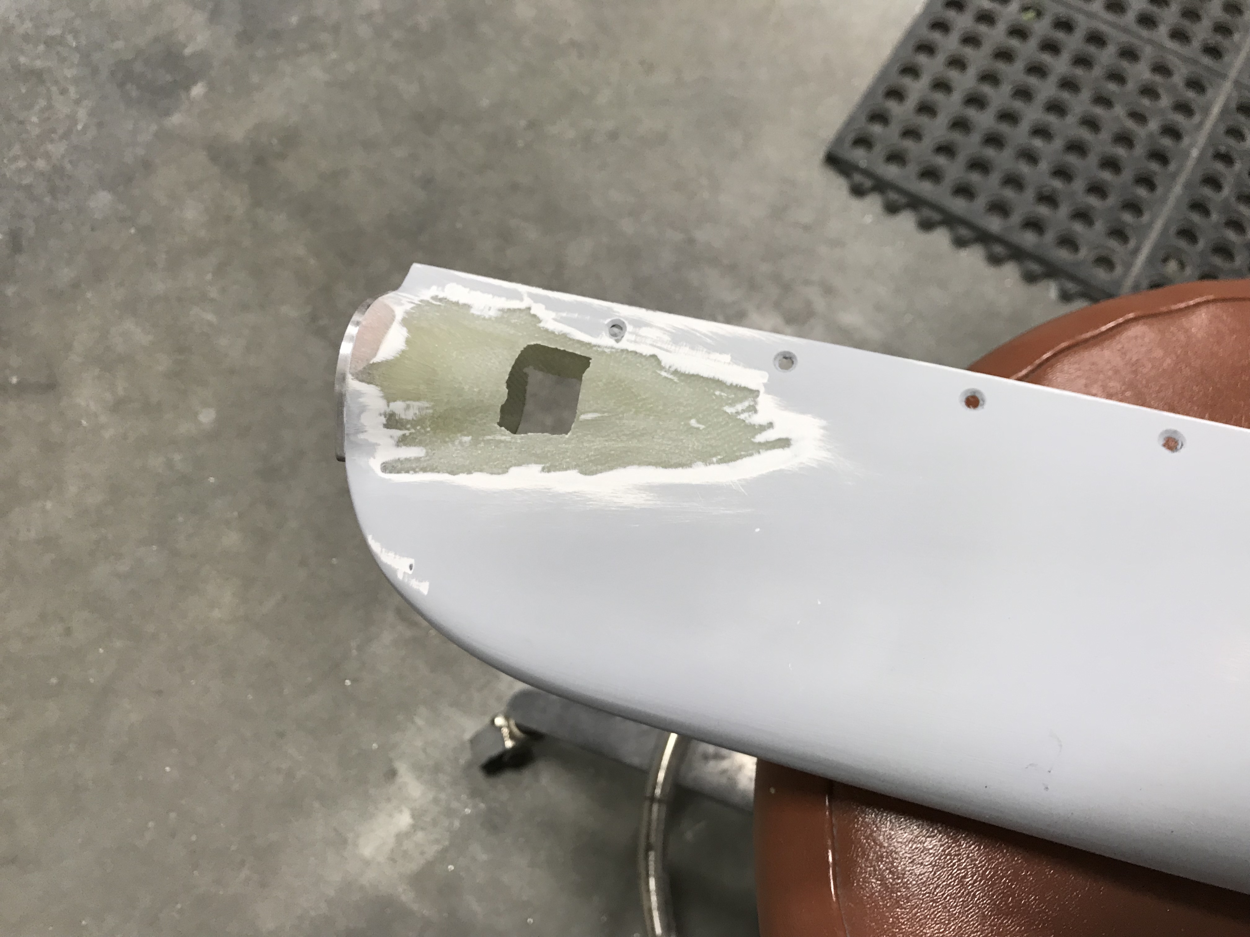
Butchering the lower rudder cap

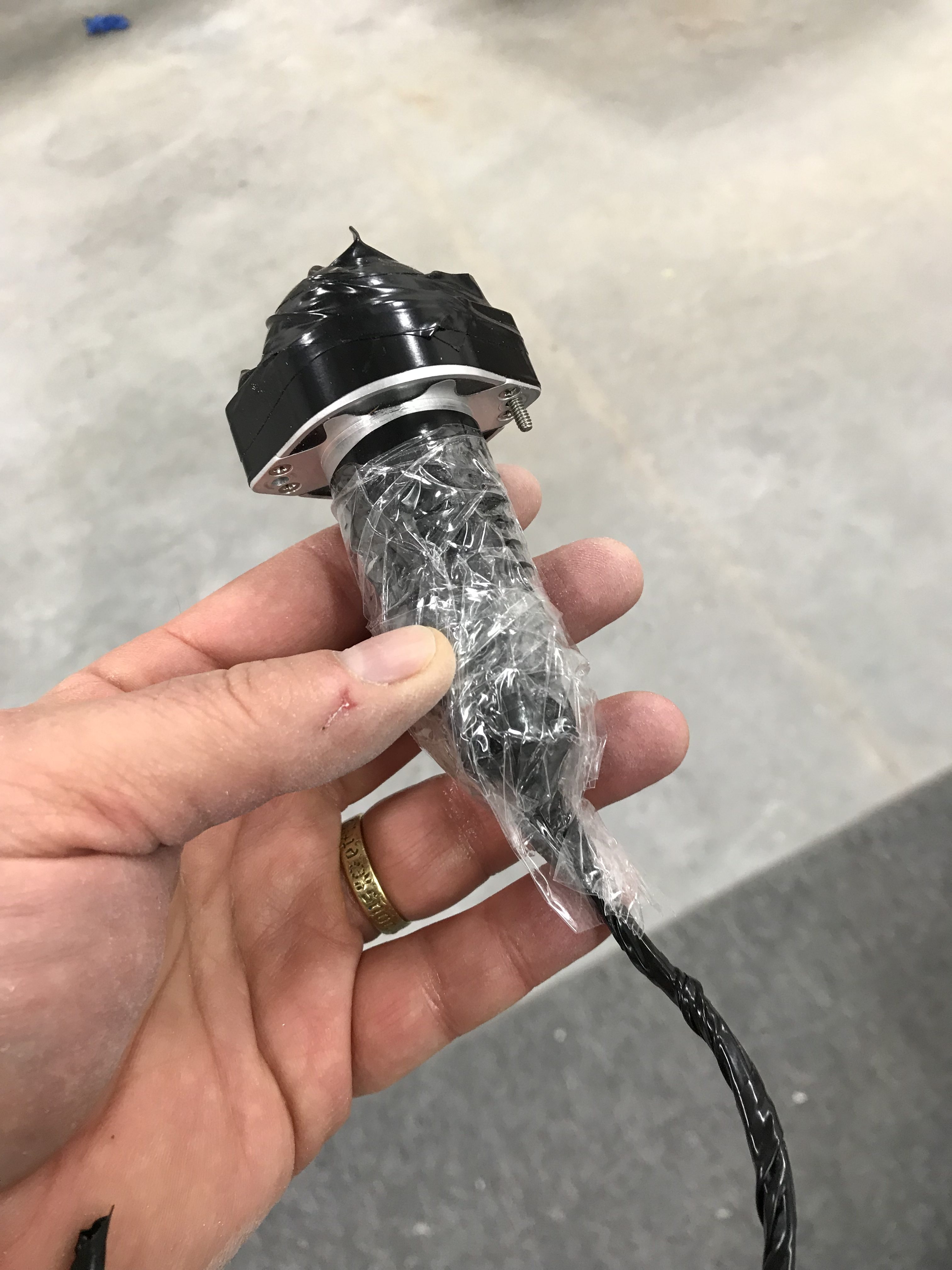
I did a rough cut to accommodate the electronics end of the light, then wrapped the light in packing tape as a release agent for the fiberglass I laid into the cutout area.

A bit of sanding around the cutout and I was ready for BID and resin.

The end result…a nicely-faired tail light! I didn’t capture a picture of the modified fairing but the change is barely perceptible from the original installation.

A few tips

I’m awaiting delivery of the avionics harness from Approach Fast Stack so I decided to tackle a task I’ve been avoiding for more than 13 years – fitting fiberglass tips to the horizontal stabilizer, elevators, vertical stabilizer and rudder. I’ve said before that I hate working with fiberglass and that’s still the case.

Van’s ships the elevator tips with no front end and recommends fairing over the counterweight with an epoxy/flox fill, essentially making it non removable. I decided to add a thin fiberglass layer over but not attached to the counterweight so that I can remove the tip later on if necessary.

Tip prep was simply sanding down the front surfaces to give the layup something to bond do.
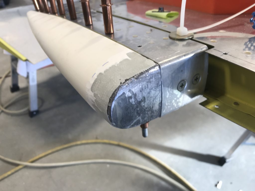
Elevator tip prepped

I laid up 3-4 layers of 9 oz BID cloth over the counterweights and front of the tip. Before doing that I covered the elevator and counterweight with clear packing tape as a mold release.
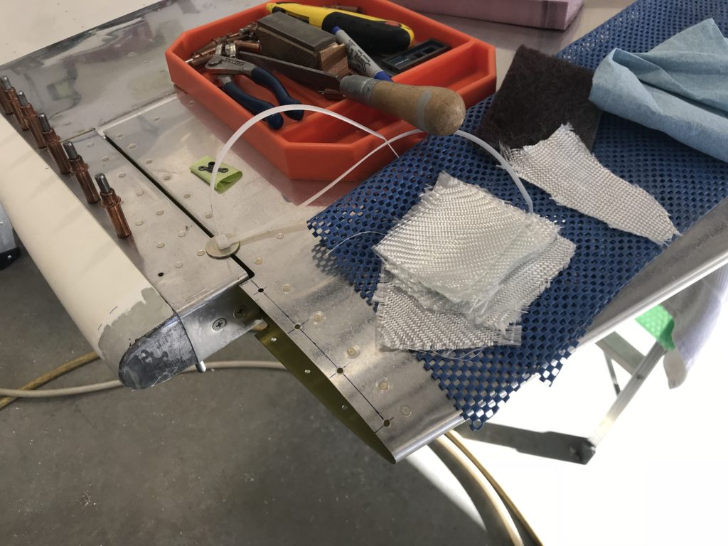
Fiberglass ready to apply

The layup initially looked too thick but when I sanded it down to match the elevator and HS tip there wasn’t much left – but there really doesn’t need to be.
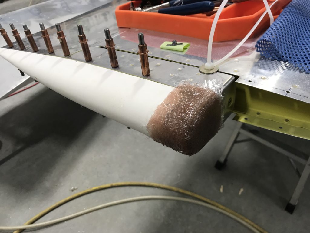
Initial fiberglass layups

Here’s the inside of the tip after removal..it conformed pretty nicely but I had some voids in the cloth that required some additional epoxy to fill.
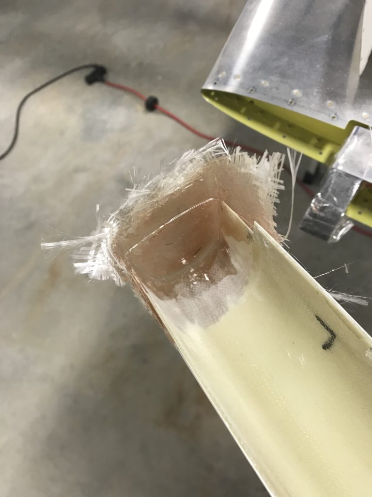
Interior of tip after removal

After sanding and before priming…looks good!
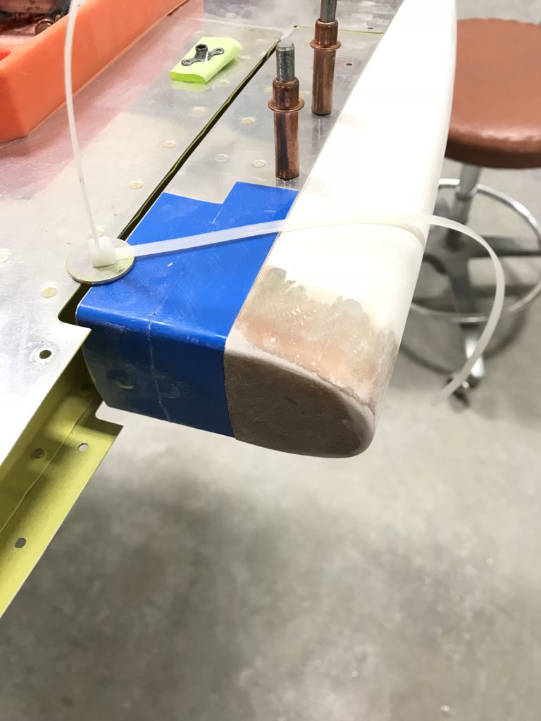
Finish-sanded tip

The HS tips come without a back end and there’s no requirement to add one but they look better and more “finished” if they’re closed – so that’s what I did, using the foam technique in Section 5 of the instructions and and a sheet of pink foam insulation from the aircraft construction department at Home Depot.
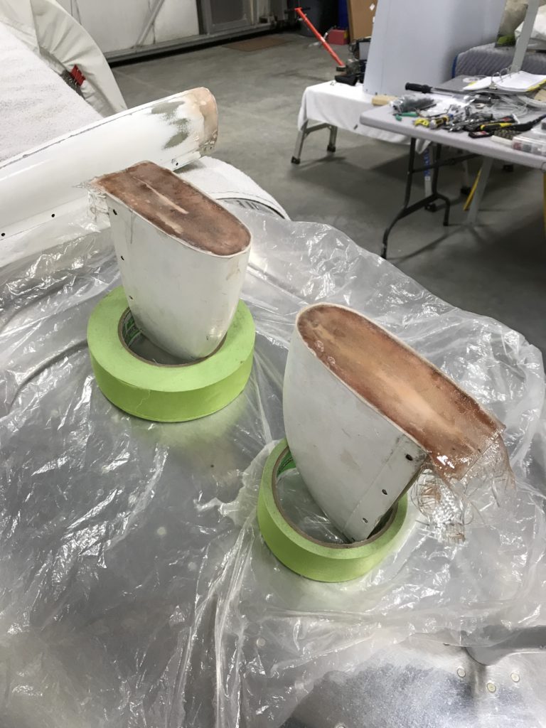
HS tips covered

The same foam closeout technique was used on the VS tip…already done in the pic below.

The rudder upper fairing was a really poor fit, a common complaint with previous versions of fiberglass parts shipped by Van’s. I had to build up the front end with balsa and fiberglass, and apply epoxy and microbaloons to fill gaps on either side.
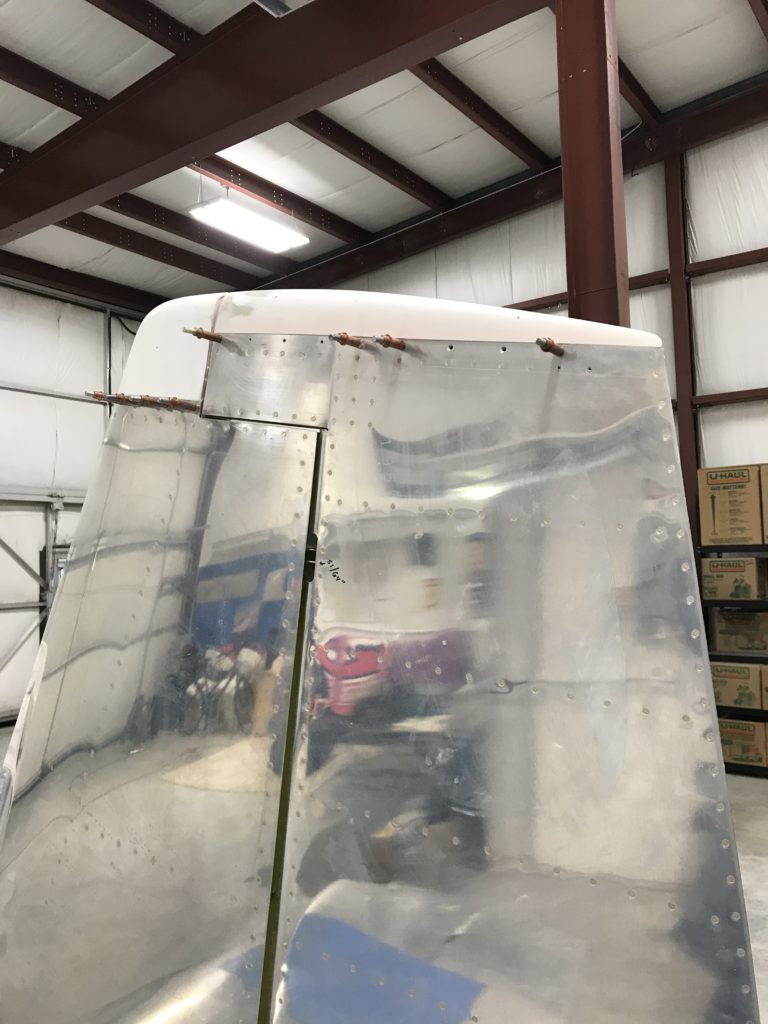
Upper VS and rudder tips

Surprisingly, the rudder lower end cap fit pretty well when trimmed to the scribe marks applied by Van’s. I decided to make it removable by adding #6 platenuts to fairing attach points on the rudder.
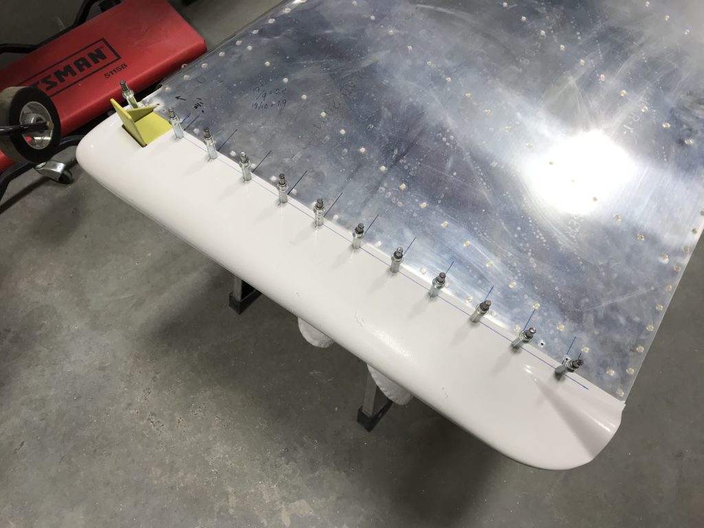
Lower rudder cap

The lower end cap looks good now, but pop-riveting the nav/strobe light attach plate caused the fairing to crack (shit!) so I had to mix up some epoxy and flox for a fix.
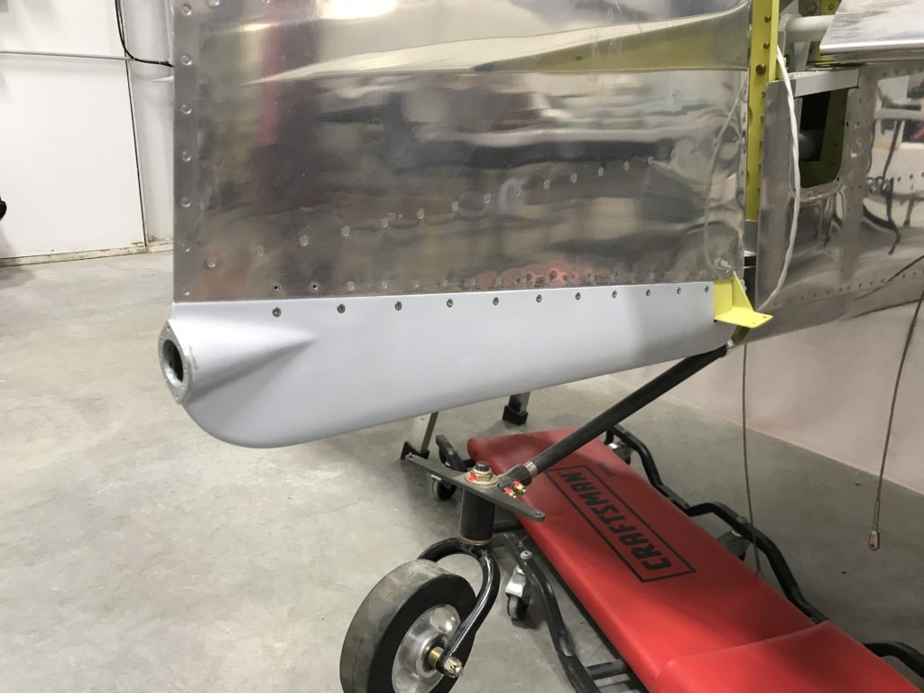
Lower rudder tip fitted

Here are all the emp tips sealed and primed with K36 primer to protect them until time for paint.
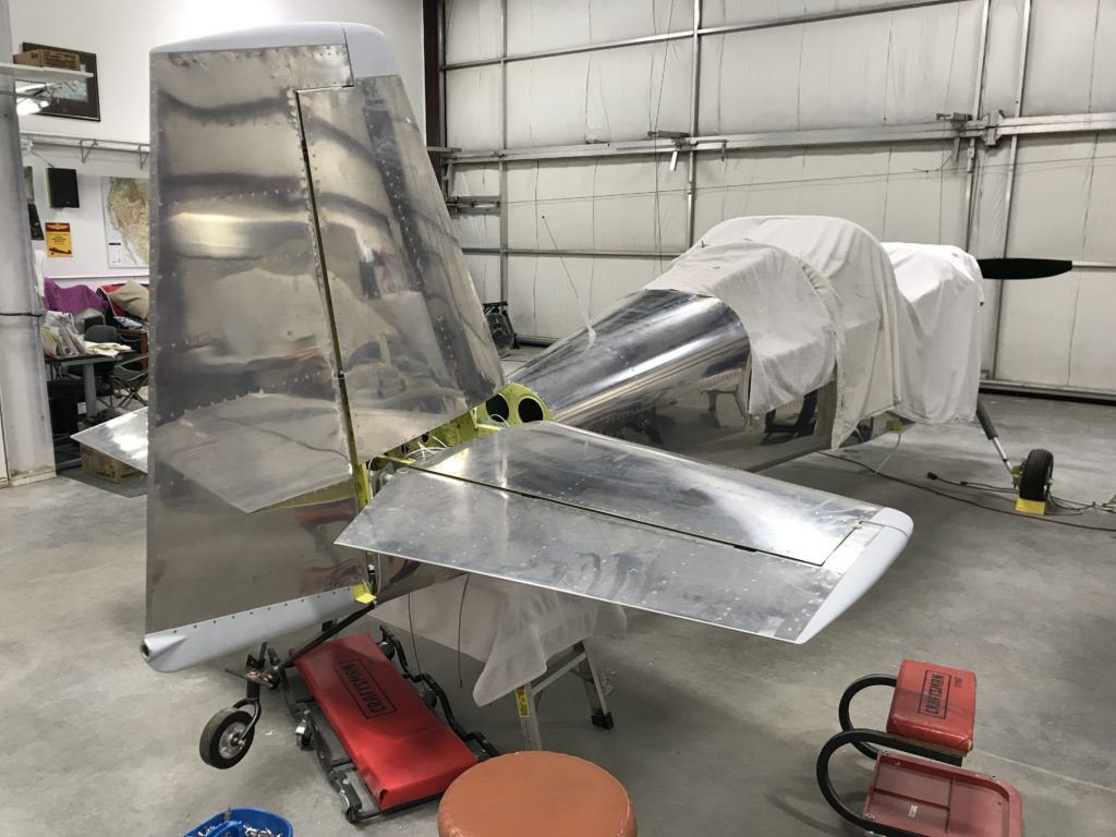
"Finished" emp tips


Rudder cables and ELT mounts

Over the course of this week I’ve been at the hangar a few times to take care of random stuff prior to mounting the wings.

Before we moved the fuse to the hangar, I installed and secured the rudder/tailwheel steering cables to the tailcone. It would have been good to check the plans and see which end of the cables attach to the rudder control horn (the two ends of the cable aren’t the same), but I neglected to do that.  Compounding that mistake, I had already fished the cables through several holes in the tailcone and aft fuse and installed snap-in plastic grommets in those holes that make it impossible to remove the rudder cable once they’re installed. As an extra bonus, the grommets can be installed with access to one side of a hole, but access to both sides of the hole is required to remove them – which is a problem in several places in the tailcone and baggage area where panels are already riveted in place that limit access. D’oh!

Other builders have made this mistake and wound up drilling out rivets and removing panels to get at the grommets, but I was determined not to do that. So…I went on a trek to Home Depot (there’s one about five minutes from the hangar – bonus!) and bought a small propane torch and an X-Acto knife.  A red-hot knife slices through plastic pretty easily, and working from one side of the hole, it’s not too hard to slice out the clips that hold the grommets in place. After an hour of heating and cutting, the grommets and the rudder cables were out.  30 minutes later, the rudder cables were installed the right way.

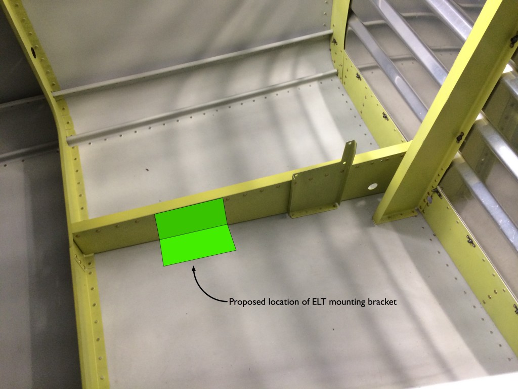
I also started working on the Emergency Locator Transmitter (ELT) mount.  Over the last several months I’ve been working out where to install the ELT and have never been very happy with a lot of the options I’ve seen, including Van’s own ELT/strobe mounting plate which seems far too flexible to ensure that the ELT will work when it’s supposed to.  Many RV builders regard the ELT as a bureaucratic nuisance and don’t care how it’s installed.  They’re certainly free to do as they see fit, but if the device has to be in the airplane, I want it to work as it’s designed to.

My friend Andy mounted his ELT on the horizontal bellcrank rib, which seems like a good place for both longitudinal strength and access for installation, testing and battery changes.  The only downside is that the rib doesn’t have a lot of lateral stiffness, and theoretically the ELT mounting surface should withstand a 100-pound pull in any direction without deflecting more than 0.1 inch.  I came up withe the idea of fabricating an L-shaped reinforcement plate to provides extra stiffness, and had my fellow FAA DER Tom – who’s a structures engineer – run the numbers to make sure my design would be strong enough while not impacting the existing structure.

Proposed ELT mountIt turns out from Tom’s analysis that a piece of 0.040″ 7075-T6 aluminum sheet, bent into the required L-shape, will do the job nicely.  It will be held in place on the vertical flange with ELT mounting bolts and the rivets which also attach the bellcrank stiffener angle, and on the horizontal flange with some AN426-3 rivets.  Easy peasy!  The only downside is that my candy-ass little Harbor Freight bending brake won’t handle 0.040″ 7075 sheet, so I’m gonna have to find someone with the appropriate tools to make the bend.  Stay tuned…

And the leading edge is finished

Got bent!

And the leading edge is finished. Closing the middle and lower sections was a four-handed operation; I squeezed the leading edges together while Ellen inserted clecos. The process was repeated after final-drilling the holes to #30 and deburring them.

Done!

And with the leading edge finished, the rudder is finished. After all the hassle with rivet guns and the tedium of setting trailing edge rivets, I’m pretty happy with the results.

Done!

Gotta have at least one picture of me and a finished product. Look close and you’ll see Ellen in a reflection from the rudder skin.

Learning how to roll and close the rudder leading edge

Get bent!

The next adventure in learning was how to roll and close the rudder leading edge. I bought both 7/8″ and 1″ dowels from Home Depot, not knowing which one would work better. As it turns out, the 1″ dowel is a better choice; following Van’s directions with a smaller diameter dowel leads to a rolled edge that has a lot of curvature toward the front edge, but not enough at the rear edge (next to the spar) to make closing a little easier. I tried moving the dowel a little closer to the spar, but it was tough to get it to stay there. Generally after a couple of bends on each side, the edge was ready for closure.

Trailing edge finished!

Double-flush rivets

I used Van’s recommended procedure for setting the trailing-edge rivets, with a few exceptions. First, I used the pneumatic squeezer to initially set rivets in the sequence recommended by the manual. Then I used the back-rivet set to get the shop heads parallel with the trailing edge. And finally, I used a swivel flush set on the manufactured side make each shop head as flush as possible with the skin. The last two steps were done to groups of four or five rivets at a time – hit one side with the back-rivet set, then flip the rudder and finish up with the flush set.

Trailing edge, left side

And the result? The trailing edge was straight to within 0.04 inches, which beats Van’s requirement of 0.1″. If you sight down the edge you’ll see some very minor pillowing or waves in the edge, but overall I’m satisfied. And there was much rejoicing. Yea.

Trailing edge finished!

Time to get that trailing edge started

Go Jackets!

I couldn’t stand it any more…it was time to get that trailing edge started. I had a 6 oz. cartridge of Proseal sitting around, mixed it up and popped it into the Semco pneumatic dispenser. The Semco gun didn’t work as well as expected, but it worked enough to get the wedge Proseal’d.

A curing wedge

Here’s the trailing edge setting up. The basement is somewhat cold – 55-60 degrees – and I left the trailing edge in this pseudo-jig for five days. We were gone for most of that time.

Almost ready to proseal

Bring on the proseal!

Almost ready to proseal the trailing edge together – here’s the rudder with upper and lower ribs mostly riveted, plus that spiffy wedge with all those beautiful countersunk holes.

New yoke arrives

The new yoke from Avery arrived yesterday afternoon, and was put to use today riveting the left rudder skin to the spar. Much better results this time! I neglected to take any new pictures, so just look at the pictures above of the rudder clecoed together, and imagine that the clecos aren’t there.