Wiring from the tail forward

There isn’t a super-convenient way to route pitch trim and magnetometer wires into the empennage, so I improvised…

Here’s the pitch trim servo wire exiting through a lightening hole in the fuse rear deck.

Routing the pitch trim wire

I liberally applied adhesive zip-tie mounts to the rear deck and glued a small piece of aluminum angle to the rear spar with 3M 4000 marine cement (easier than riveting) to hold another zip tie.

Pitch trim wire over the HS sparThe black material is self-closing anti-chafe wire bundling I found at McMaster-Carr. The plans call for running trim wires along the front of the left elevator and into the trim servo bay. I think this is better than running wire through the existing manual trim cable holes as repeated elevator movement over time slightly twists the cable rather than bending it – much better from a wire fatigue/failure perspective.

Routing pitch trim wire into the elevator

You’ll see in this picture how the trim servo cable is routed into the left elevator and why some support is necessary where the cable crosses the HS rear spar.

Pitch trim servo ready for installation

And here’s the wired trim servo ready to be stuffed into the elevator. It’s slightly tricky to route the cable so it doesn’t interfere with the servo’s jack screw, but I think I’ve managed to get everything done correctly.

A happy New Years at the ThermosWorks

After more than 12 years, the rudder and elevators are mounted to the empennage and they’re moving freely without binding. Took a lot of fiddling with washers and spacers, and some expert help from my Tech Counselor (thanks Bob!) to make that happen, but it’s done.

Here’s a short demo of today’s work…

A few tips

I’m awaiting delivery of the avionics harness from Approach Fast Stack so I decided to tackle a task I’ve been avoiding for more than 13 years – fitting fiberglass tips to the horizontal stabilizer, elevators, vertical stabilizer and rudder. I’ve said before that I hate working with fiberglass and that’s still the case.

Van’s ships the elevator tips with no front end and recommends fairing over the counterweight with an epoxy/flox fill, essentially making it non removable. I decided to add a thin fiberglass layer over but not attached to the counterweight so that I can remove the tip later on if necessary.

Tip prep was simply sanding down the front surfaces to give the layup something to bond do.

Elevator tip prepped

I laid up 3-4 layers of 9 oz BID cloth over the counterweights and front of the tip. Before doing that I covered the elevator and counterweight with clear packing tape as a mold release.

Fiberglass ready to apply

The layup initially looked too thick but when I sanded it down to match the elevator and HS tip there wasn’t much left – but there really doesn’t need to be.

Initial fiberglass layups

Here’s the inside of the tip after removal..it conformed pretty nicely but I had some voids in the cloth that required some additional epoxy to fill.

Interior of tip after removal

After sanding and before priming…looks good!

Finish-sanded tip

The HS tips come without a back end and there’s no requirement to add one but they look better and more “finished” if they’re closed – so that’s what I did, using the foam technique in Section 5 of the instructions and and a sheet of pink foam insulation from the aircraft construction department at Home Depot.

HS tips covered

The same foam closeout technique was used on the VS tip…already done in the pic below.

The rudder upper fairing was a really poor fit, a common complaint with previous versions of fiberglass parts shipped by Van’s. I had to build up the front end with balsa and fiberglass, and apply epoxy and microbaloons to fill gaps on either side.

Upper VS and rudder tips

Surprisingly, the rudder lower end cap fit pretty well when trimmed to the scribe marks applied by Van’s. I decided to make it removable by adding #6 platenuts to fairing attach points on the rudder.

Lower rudder cap

The lower end cap looks good now, but pop-riveting the nav/strobe light attach plate caused the fairing to crack (shit!) so I had to mix up some epoxy and flox for a fix.

Lower rudder tip fitted

Here are all the emp tips sealed and primed with K36 primer to protect them until time for paint.

"Finished" emp tips


The tail end

Over the last month and a half I’ve been slowly working on getting the horizontal and vertical stabilators attached. There’s nothing terribly complex here, but there are some places where access for drilling holes and installing fasteners is tough.

Starting with the horizontal stabilizer, I aligned it with the fuselage per plans and drilled the inboard holes that attach the forward spar. Access isn’t so good here for a regular drill so I used the angle drill and my technique wasn’t great…despite using an undersize drill bit, the holes wound up oversize.

2015-04-04 14.30.48

The outboard holes were easier to drill, but required some extra care to ensure that edge distance was maximized on the stabilizer, fuselage longerons and bulkhead. I drilled these holes initially to #30 to check alignment, then final-drilled them to #12.

2015-04-04 14.41.53

I talked with Vans about how to handle the oversized inboard holes. Their recommendation was to upsize the holes to 0.25″ and use AN4 fasteners. Before I did that, though, I wanted to try a first-oversize close tolerance NAS6604 fastener that’s approximately 1/64″ larger than a norman AN3 fastener. That would preserve 2D edge distance on the hole. I reamed the oversize holes to accommodate the NAS6604 bolt, and the bolts were a perfect fit – problem solved.

2015-04-18 15.57.13

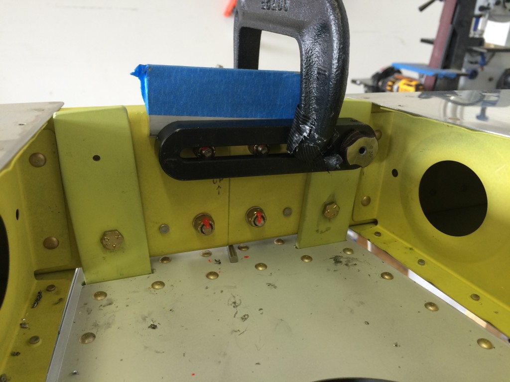
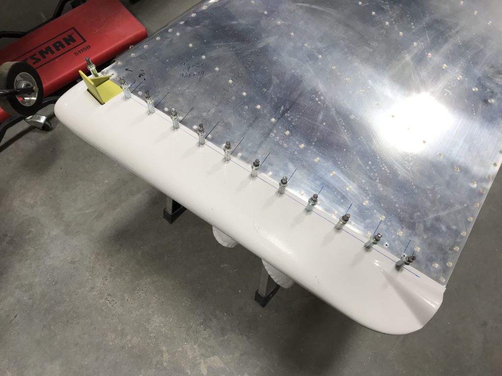
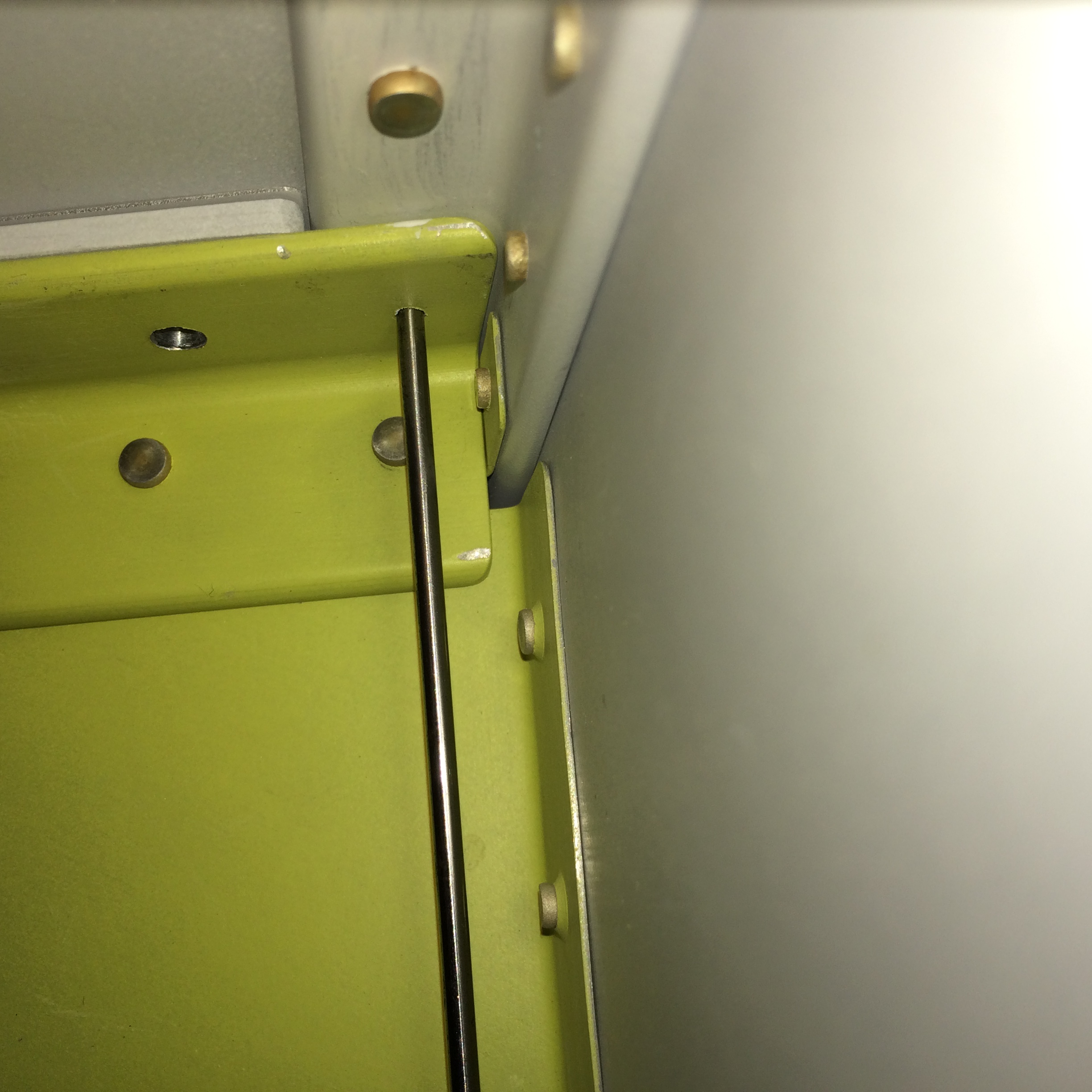
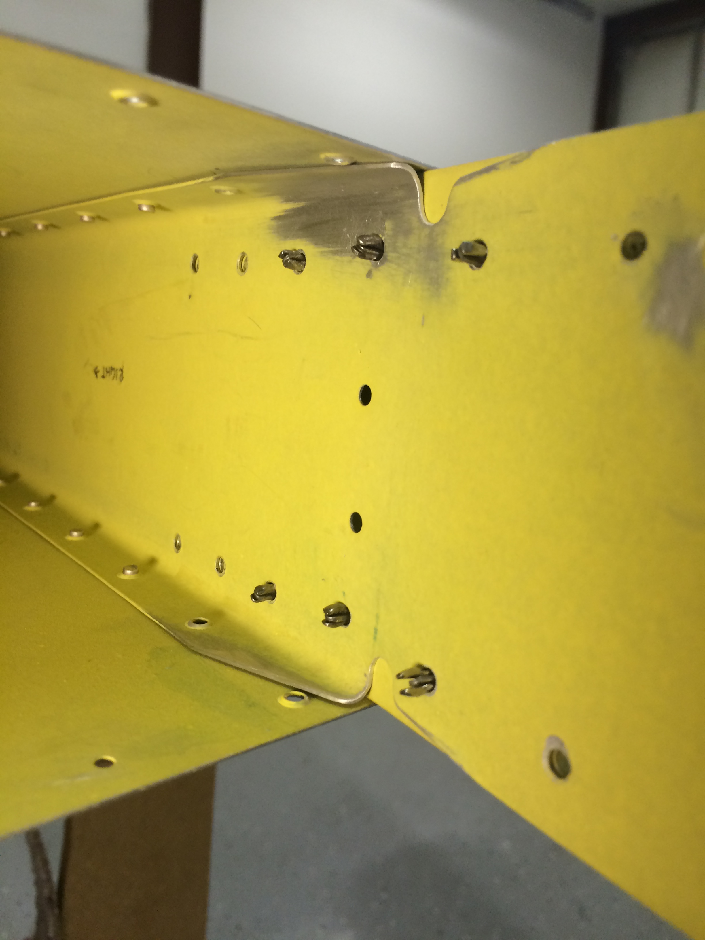
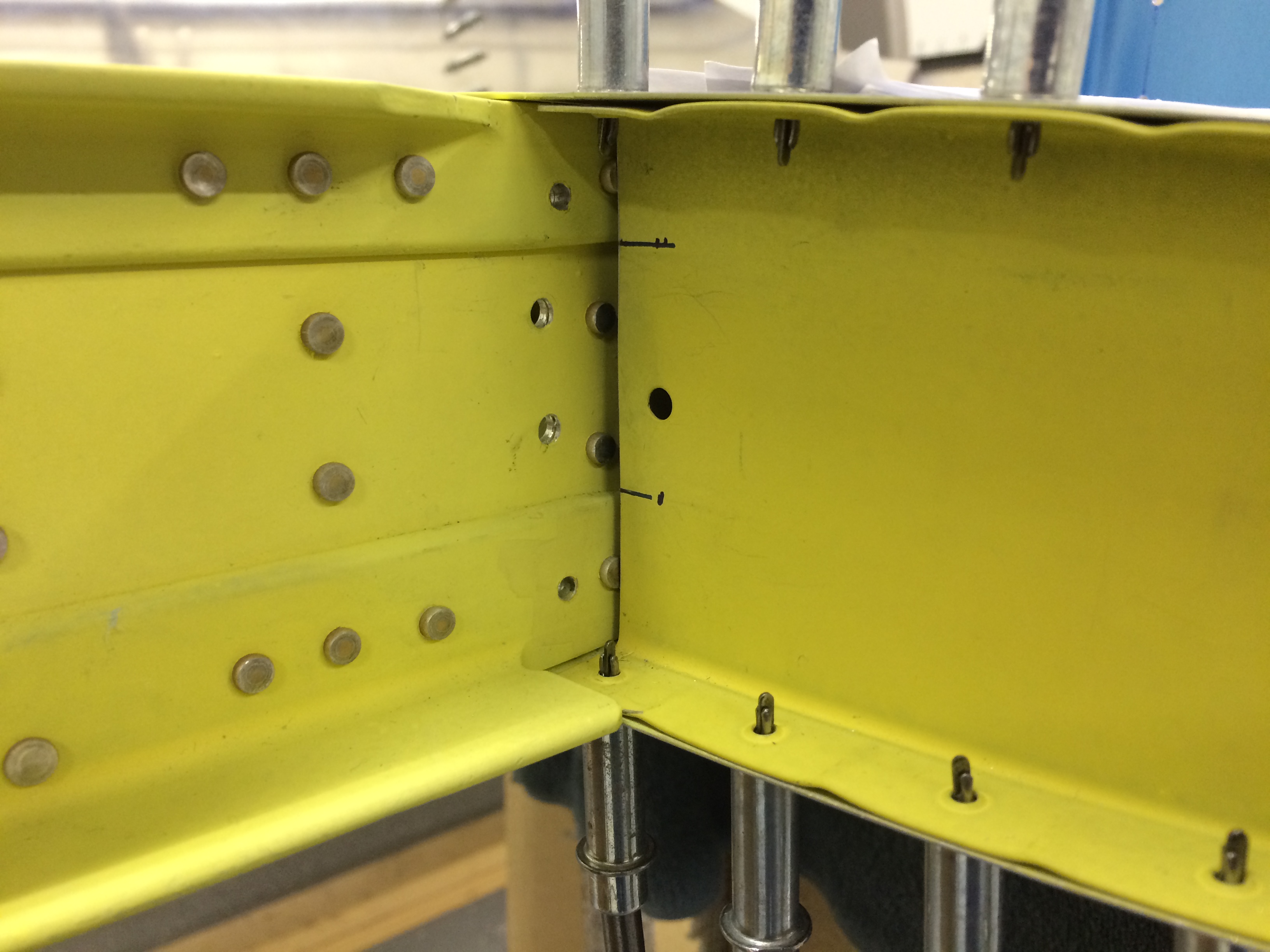
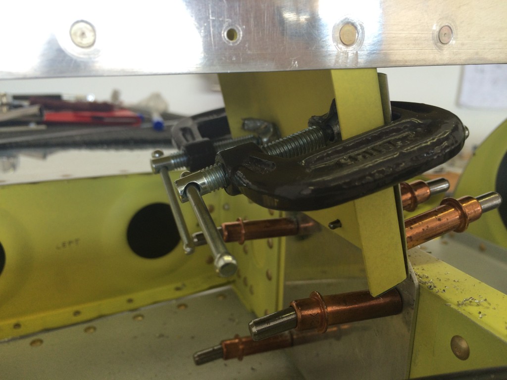
With the forward horizontal stab spar drilled to the fuse, I clamped the rear spar to the fuselage attach bars. If you look carefully, you’ll see the business end of a 3/16″ punch between the rear spar and fuselage aft deck. That 3/16″ gap establishes proper incidence for the horizontal stab relative to the fuselage.

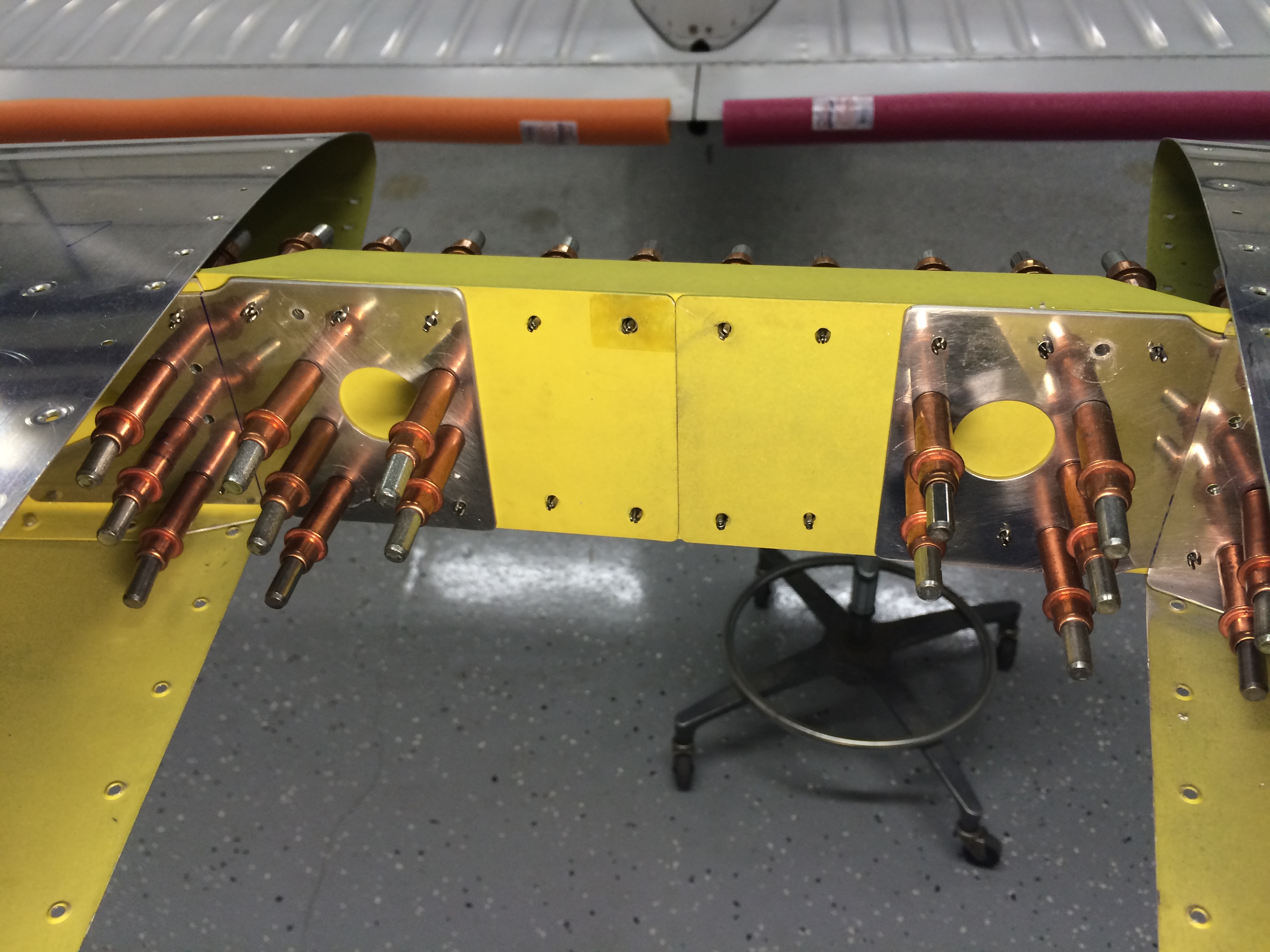
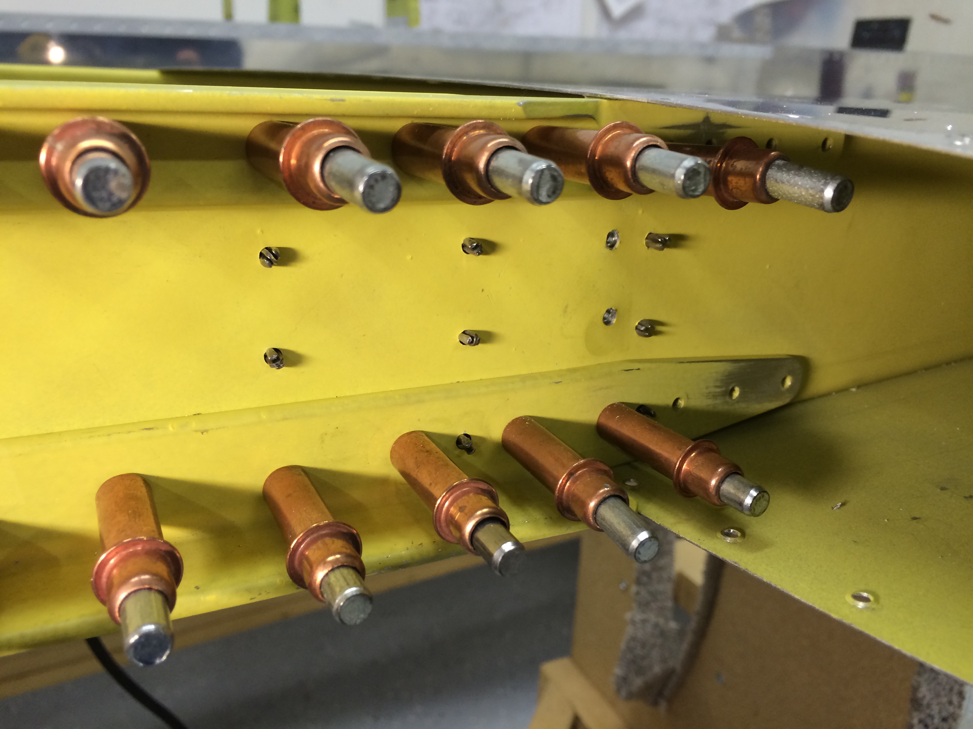
With that gap set, I clamped the fuse bars and rear spar together, and using my Brown Tool drill block, drilled the four #12 holes that hold the assembly together.  I use the drill block whenever I can…it works great for getting nice, clean, straight holes.

2015-04-19 18.20.47

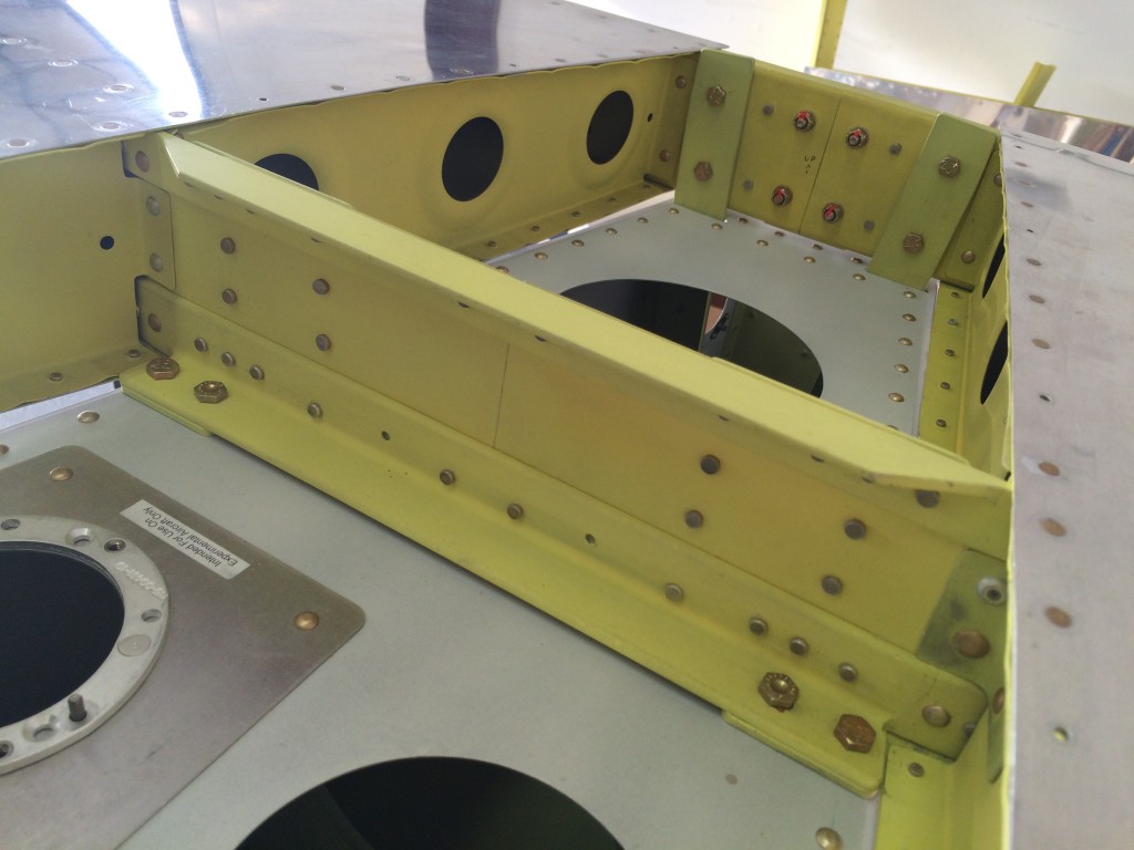
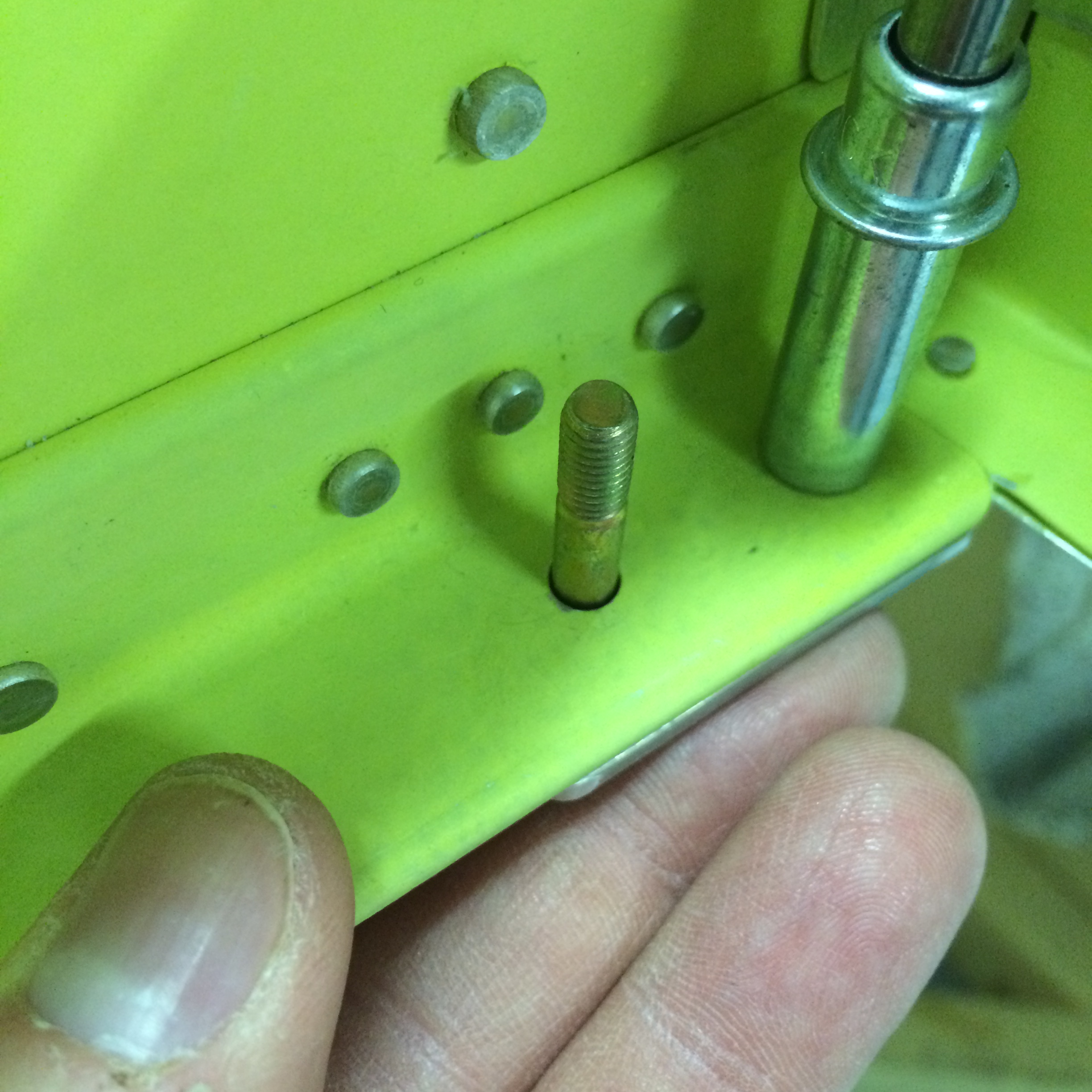
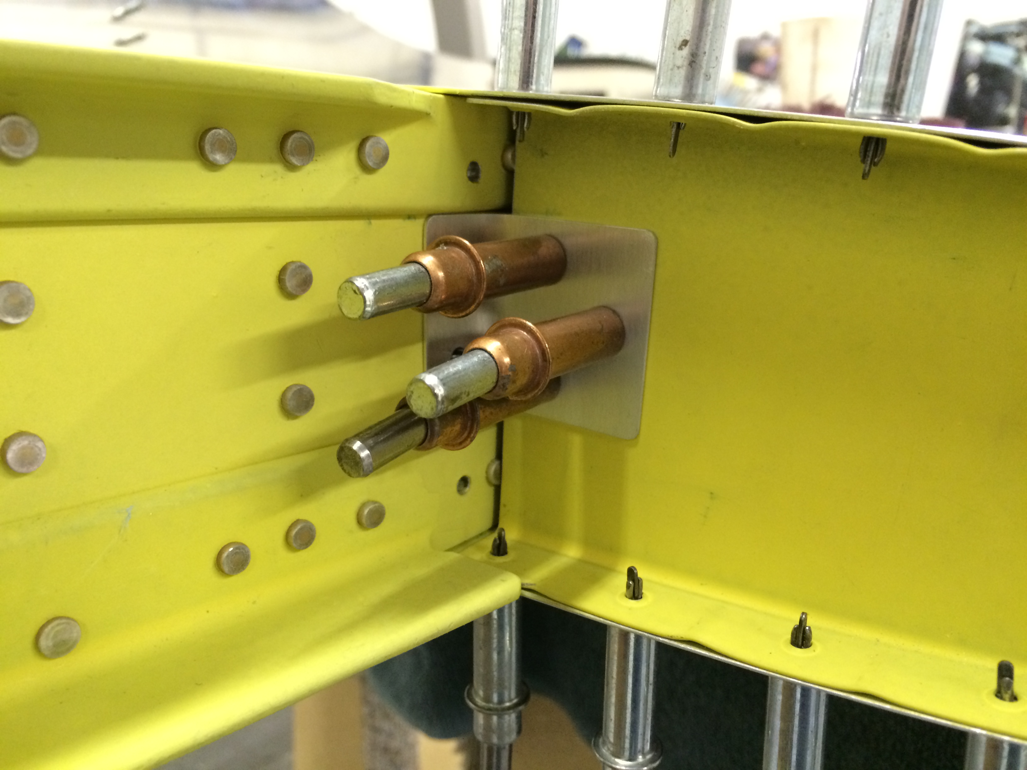
Here’s everything bolted in place. Look carefully and you’ll see the dimpled heads of the NAS6604 bolts on the front spar.

2015-04-19 18.20.22

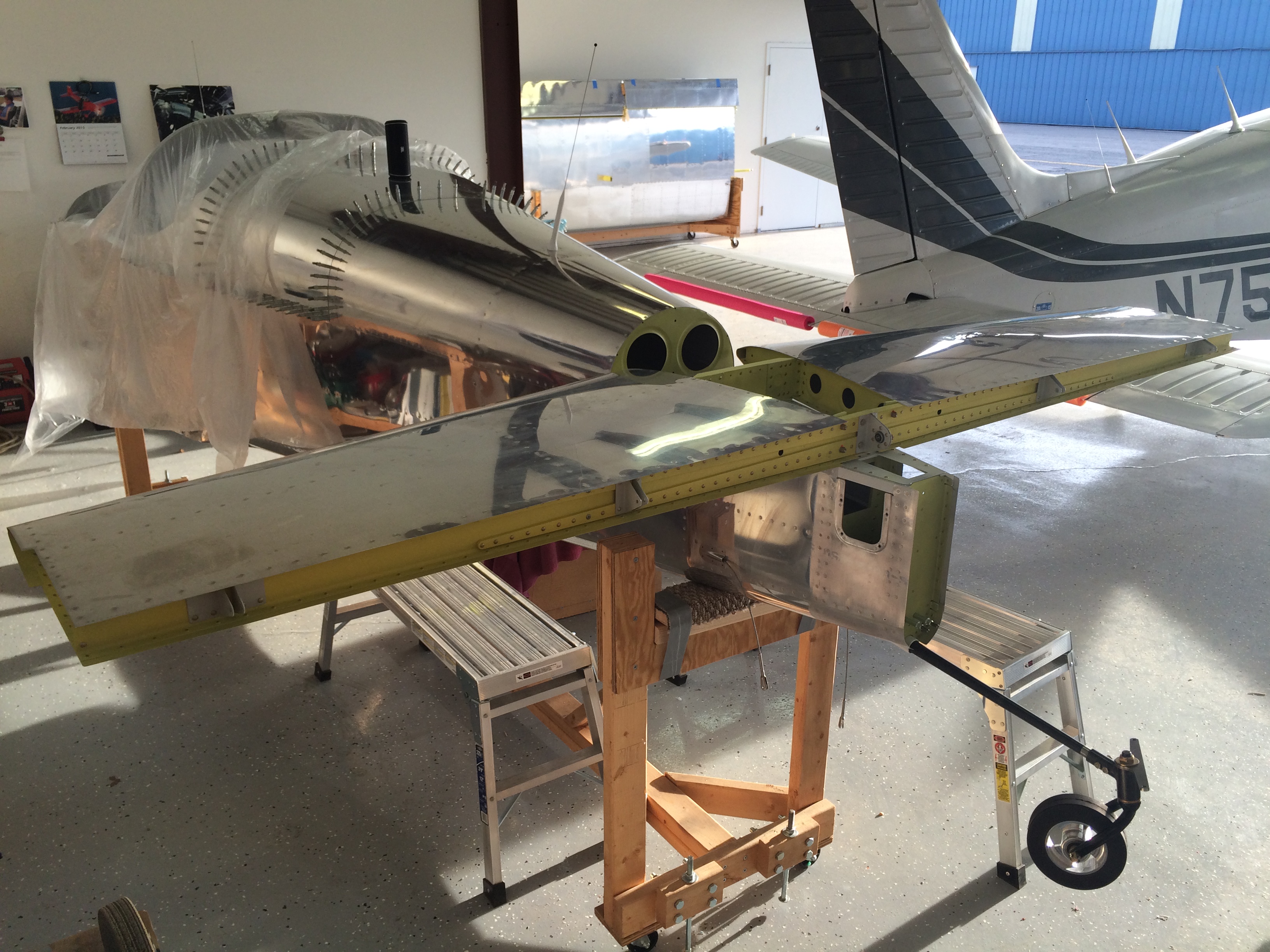
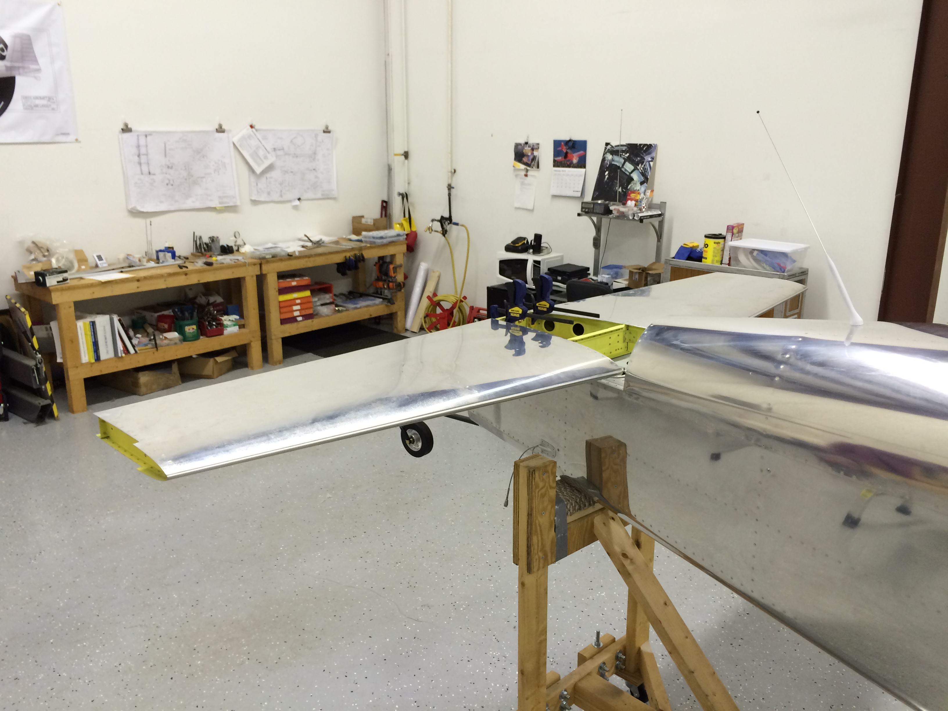
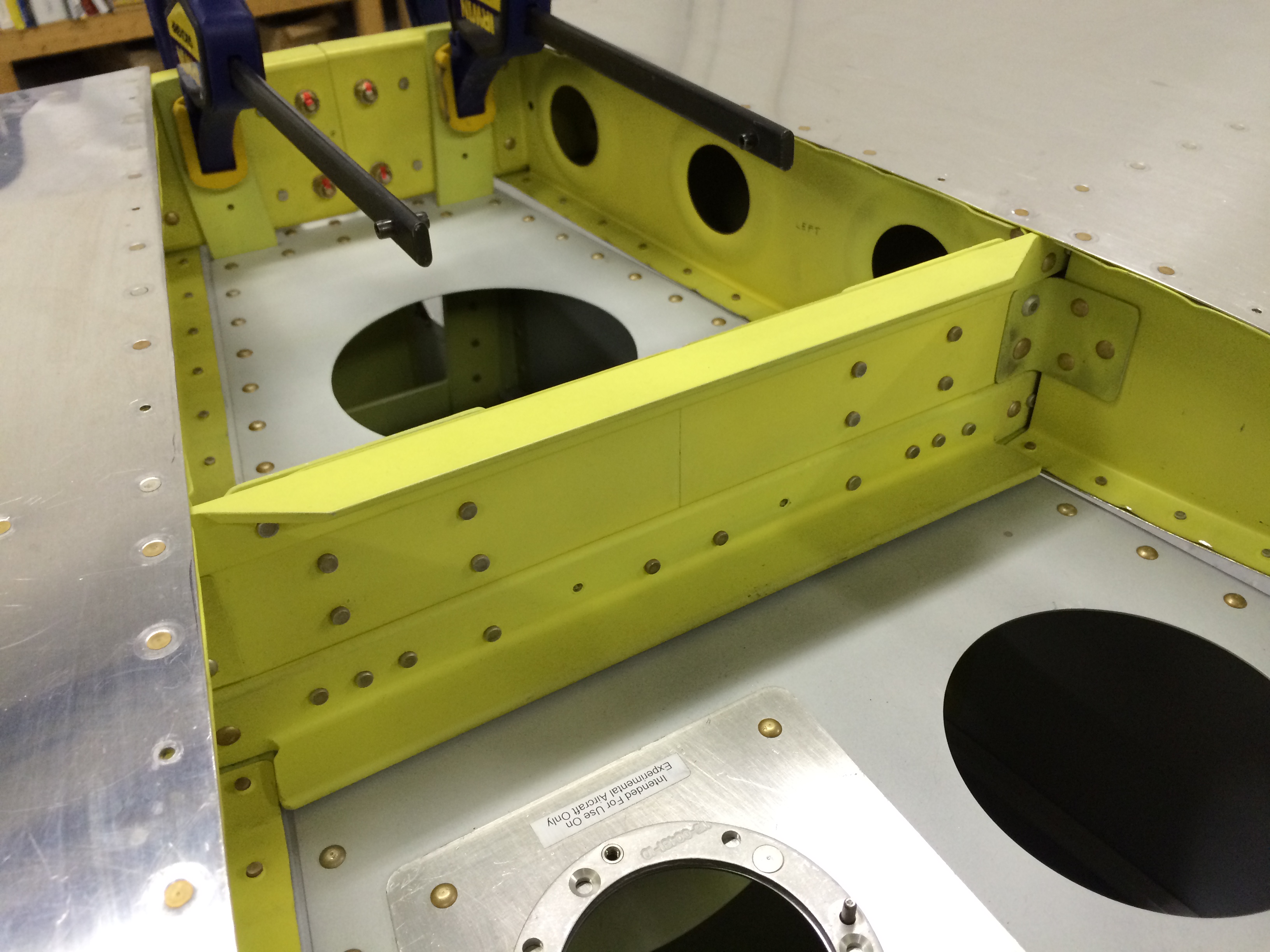
Here’s the HS stab in place. It’s been sitting in storage for ten years…and now it’s part of the airplane. Cool.

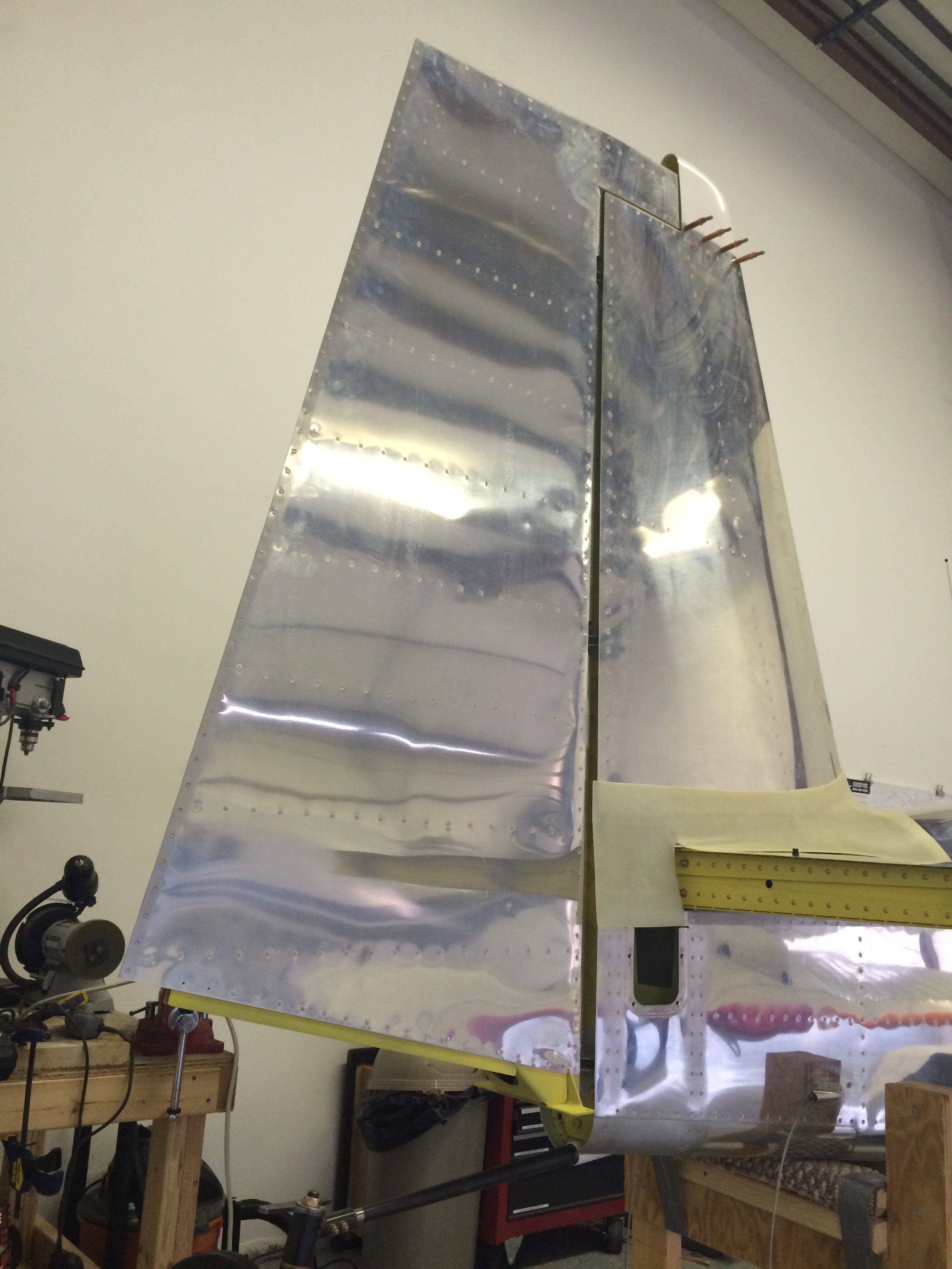
The next step was to attach the vertical stabilizer.  There are several steps in this process, and a couple of them were somewhat tricky. Just getting the vertical stab aligned correctly was a challenge – it was tough to get everything clamped in place firmly enough that the vertical stab didn’t shift while measuring its alignment relative to the horizontal stab.

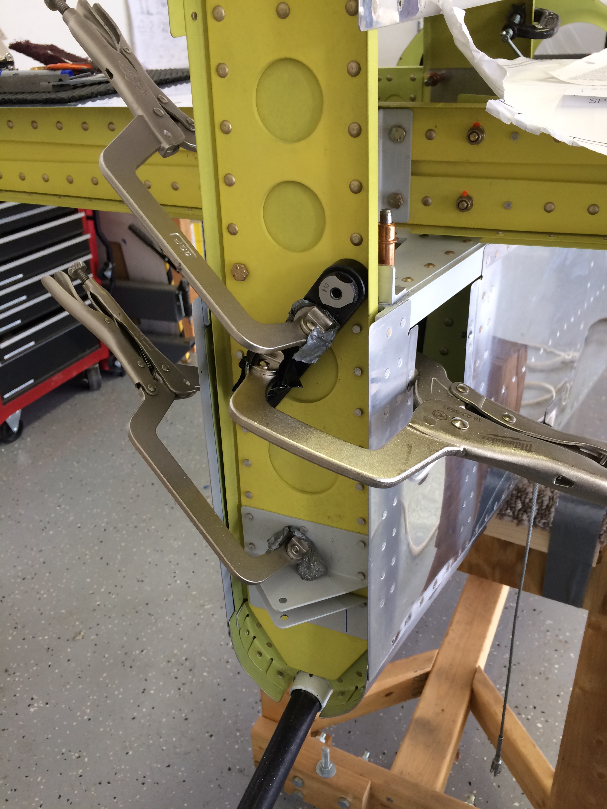
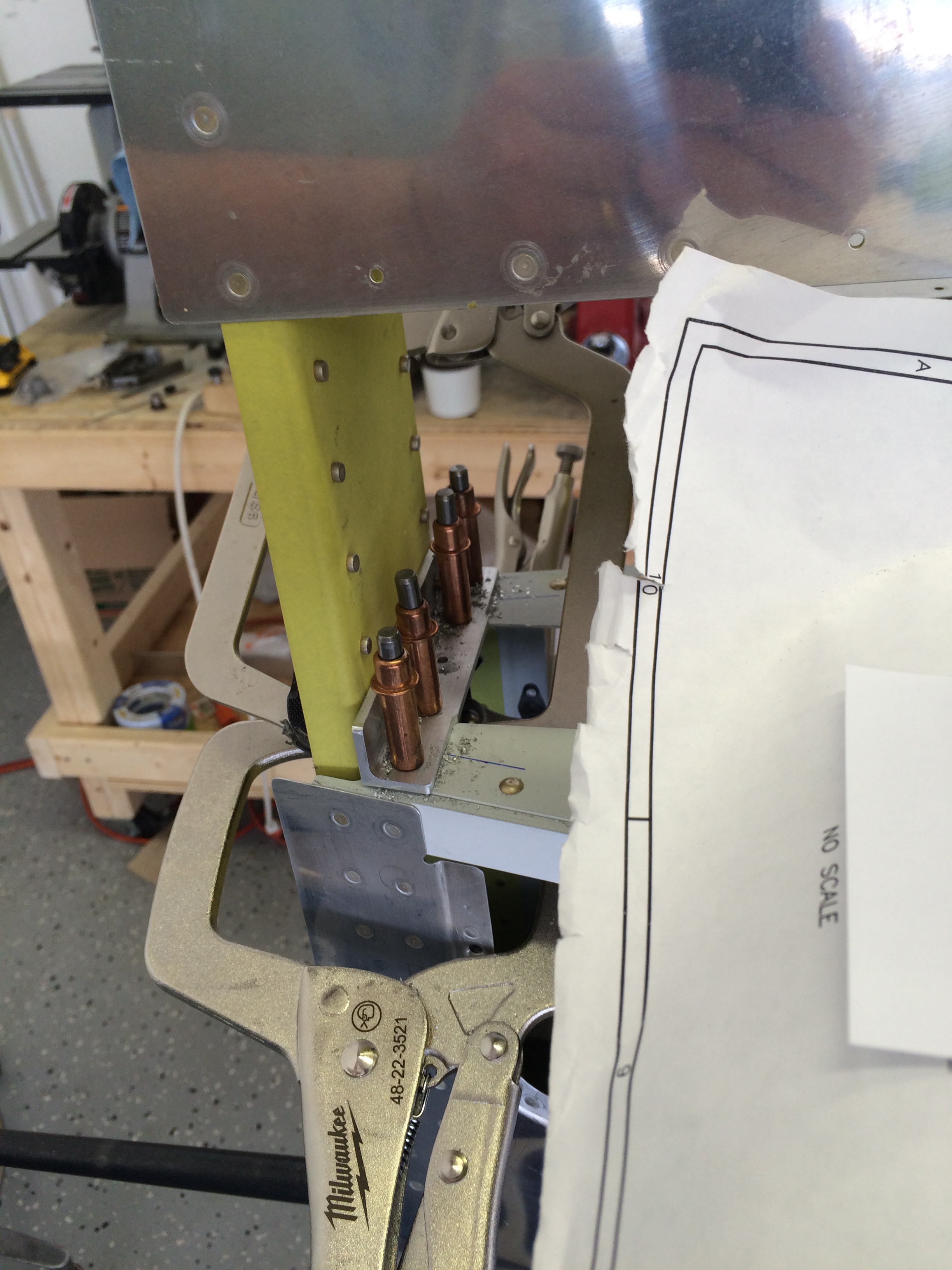
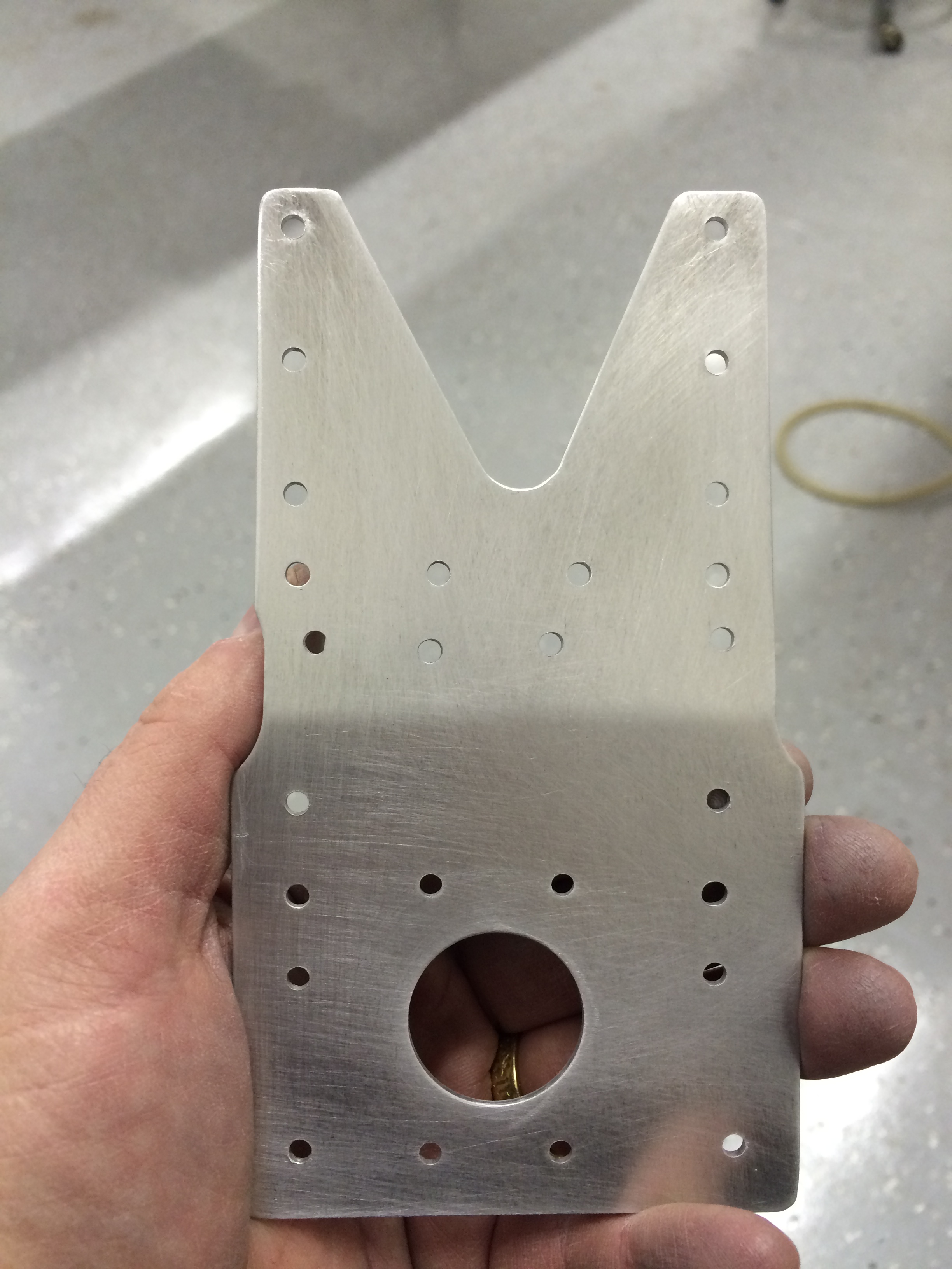
I had already fabricated the upper stab attach bracket and match-drilled it to the fuselage – with the stab aligned I used my trusty drill block and match-drilled the attach bracket to the stab. All those vise-grip clamps I’ve been collecting sure came in handy.

Drilling upper VS attach

Upper VS attach bracket
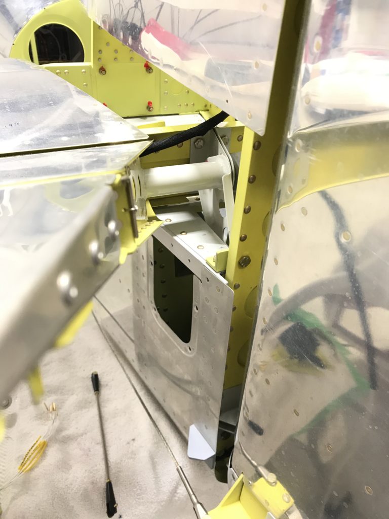
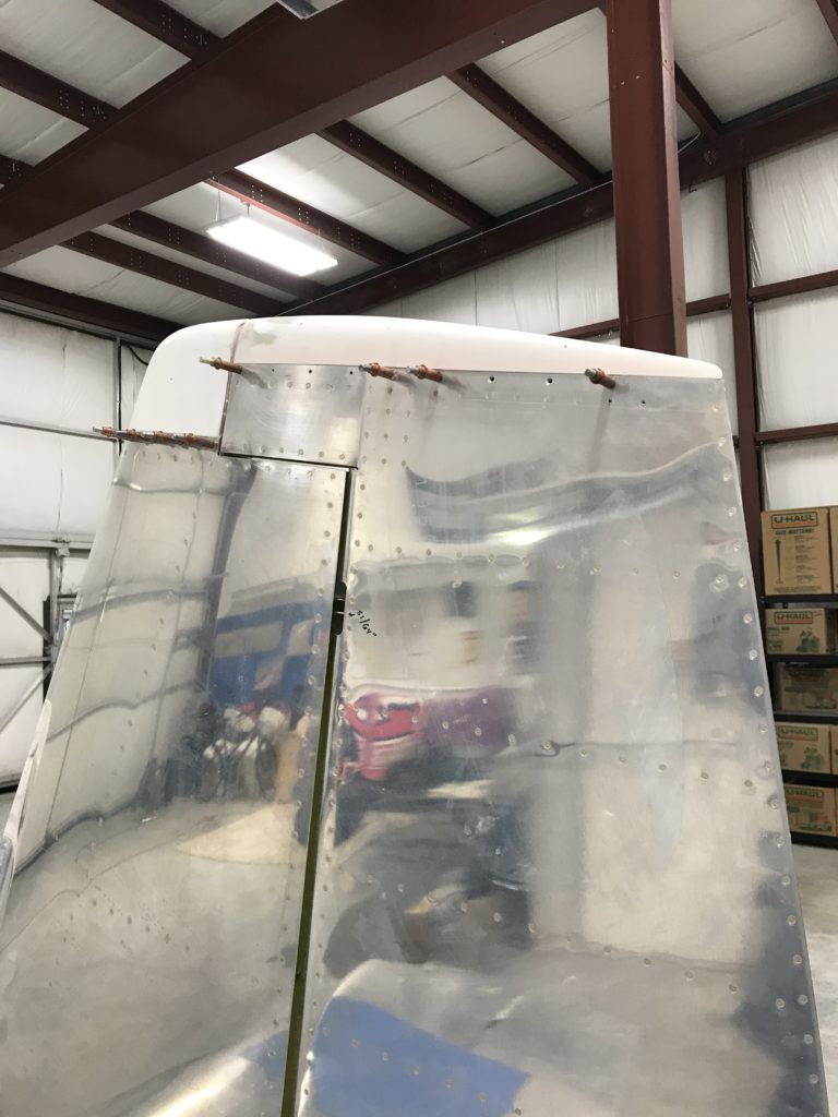
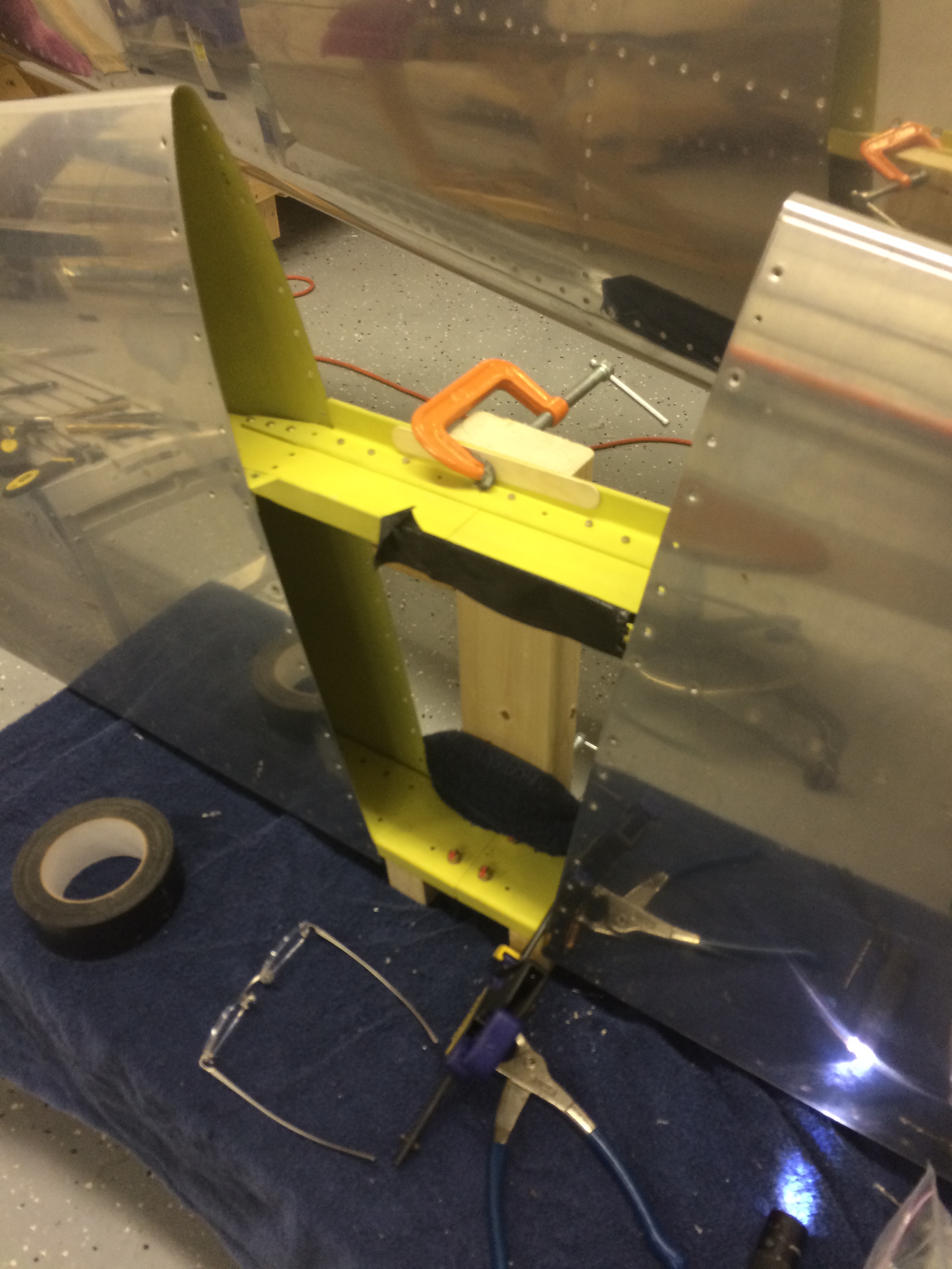
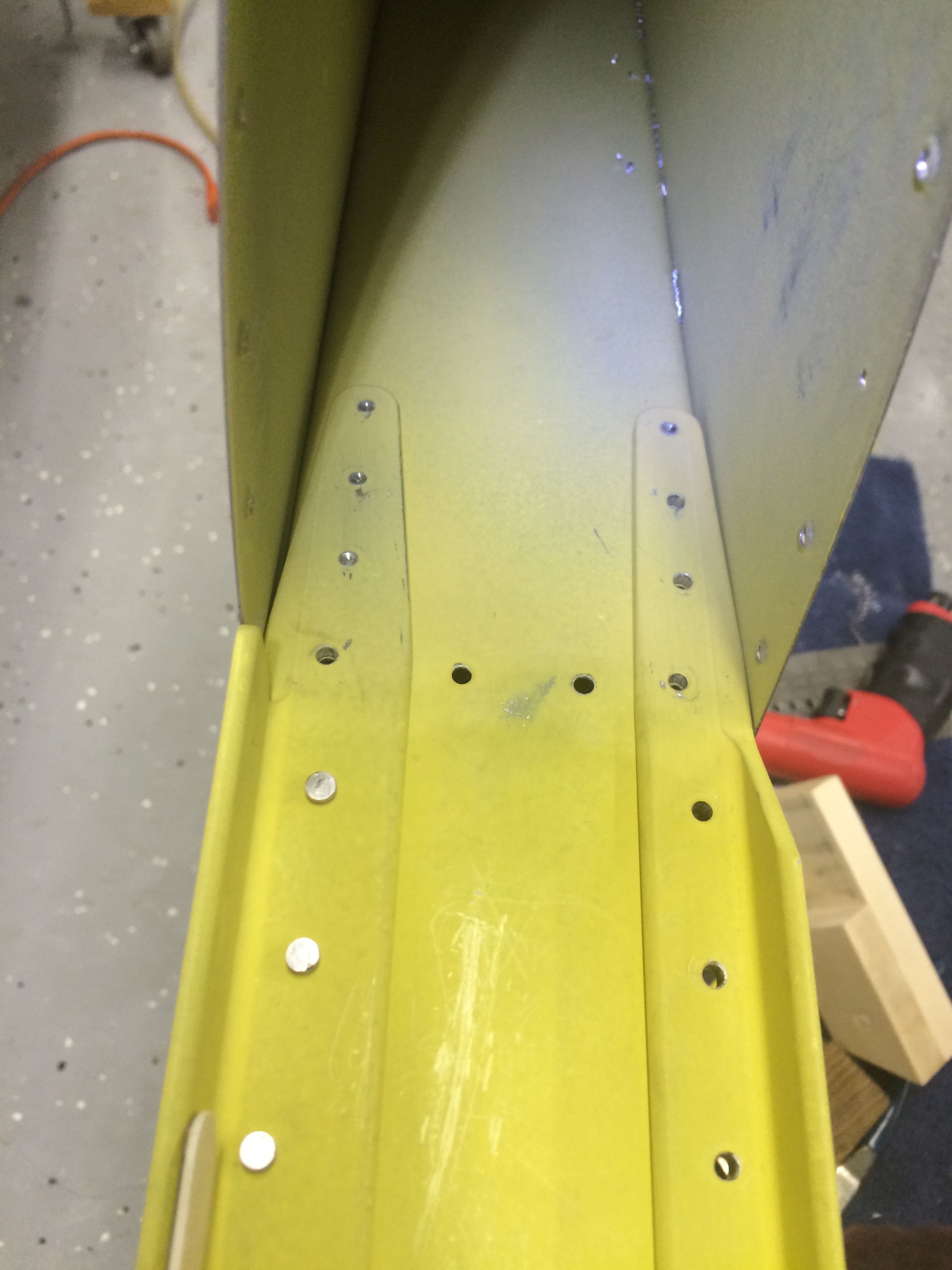
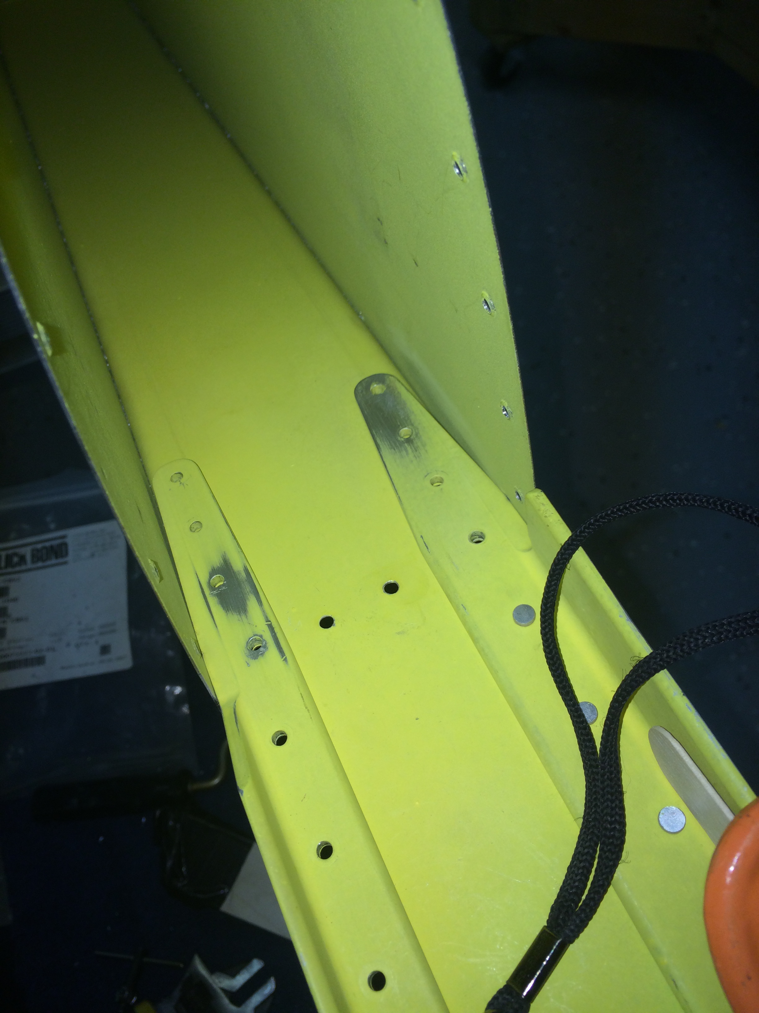
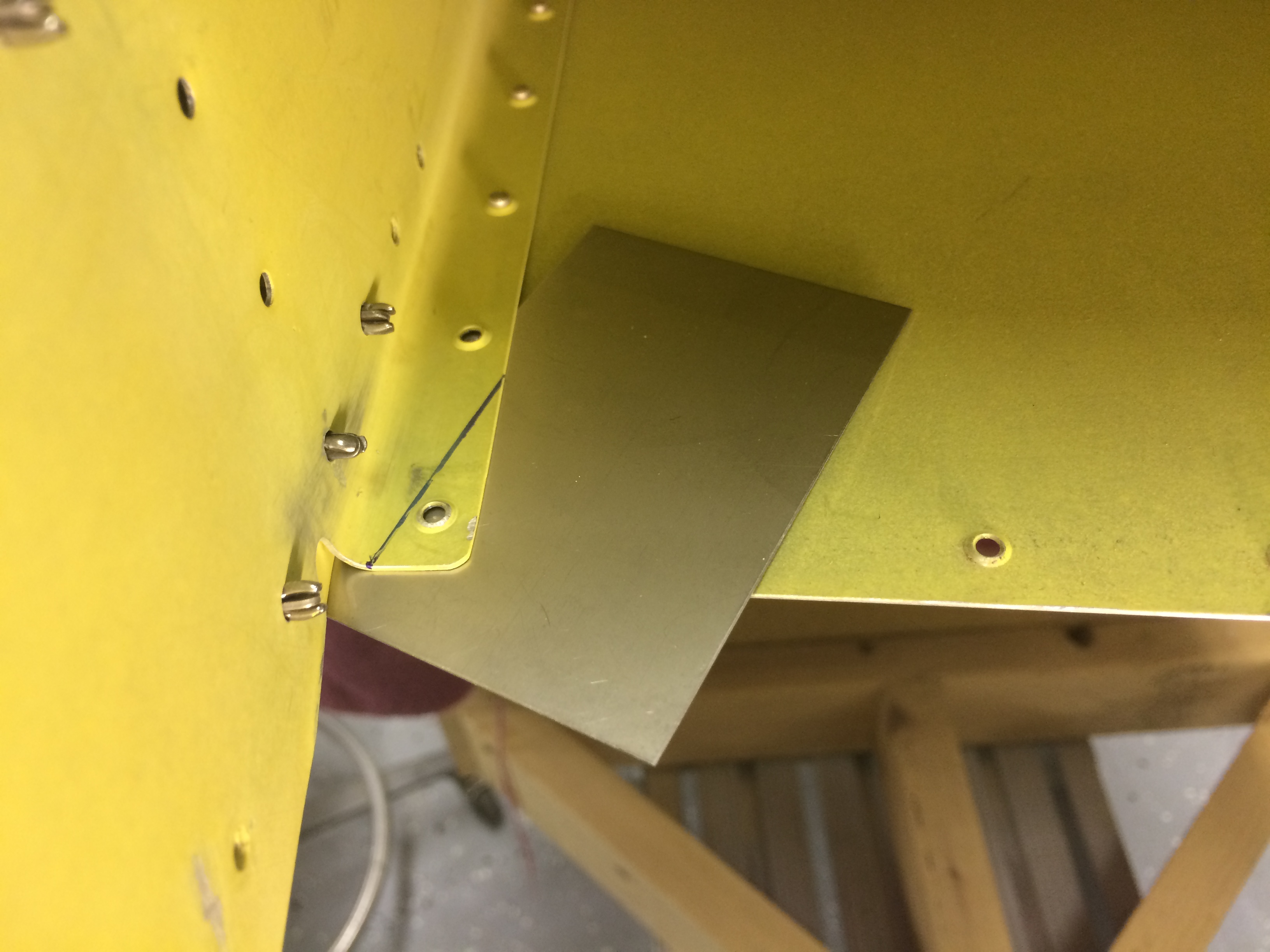
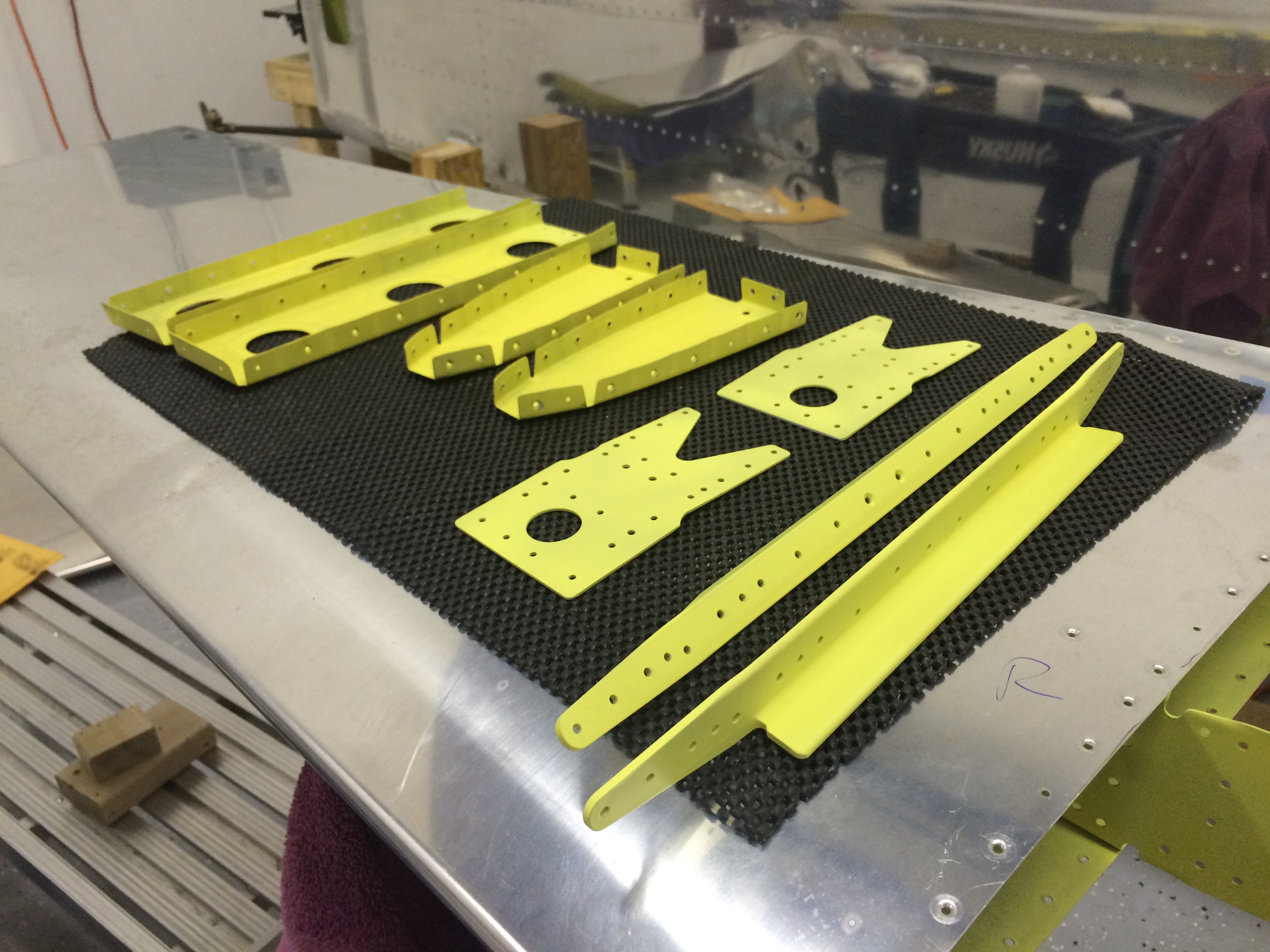
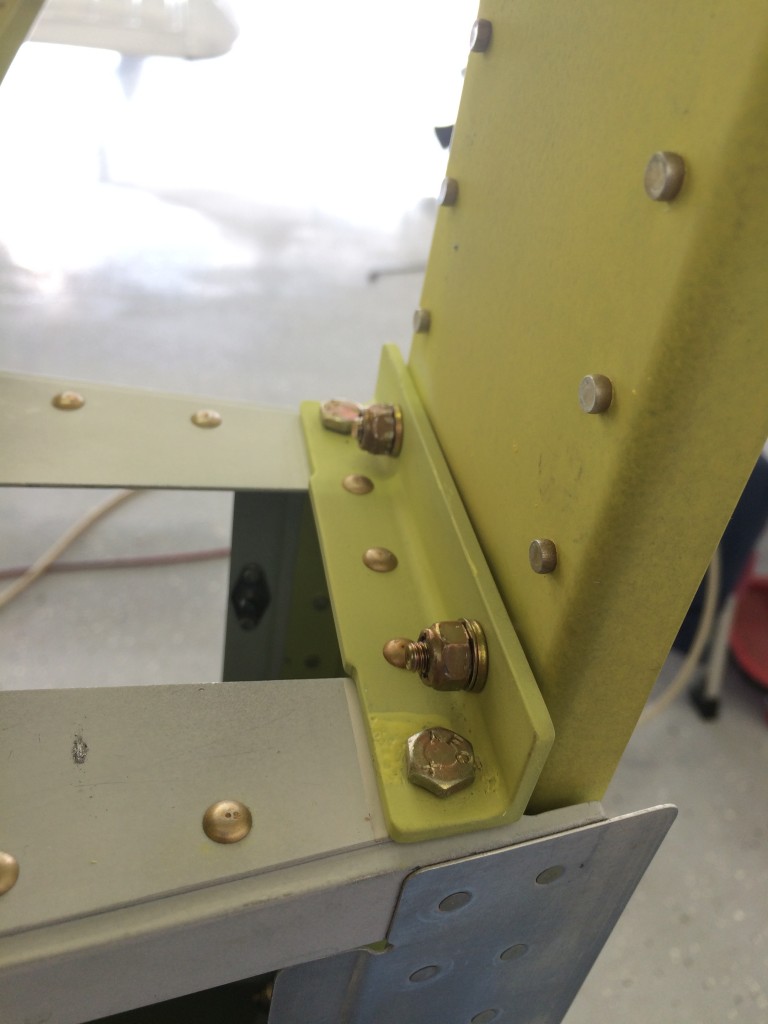
After the upper attach bracket was match-drilled, I fitted the angled attach plate that connects the vertical and horizontal stabilizer forward spars.

Drilling VS front spar 1 
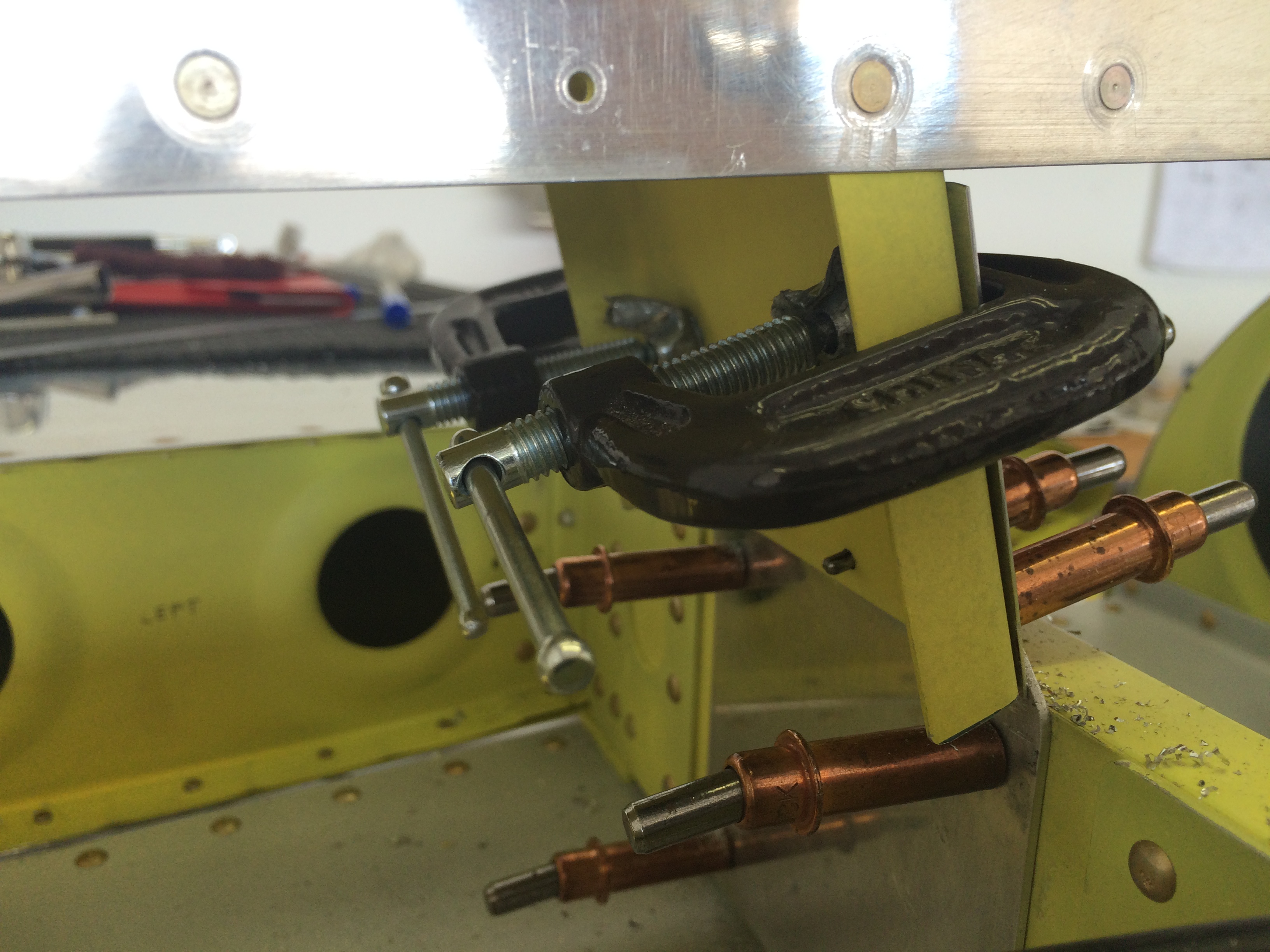
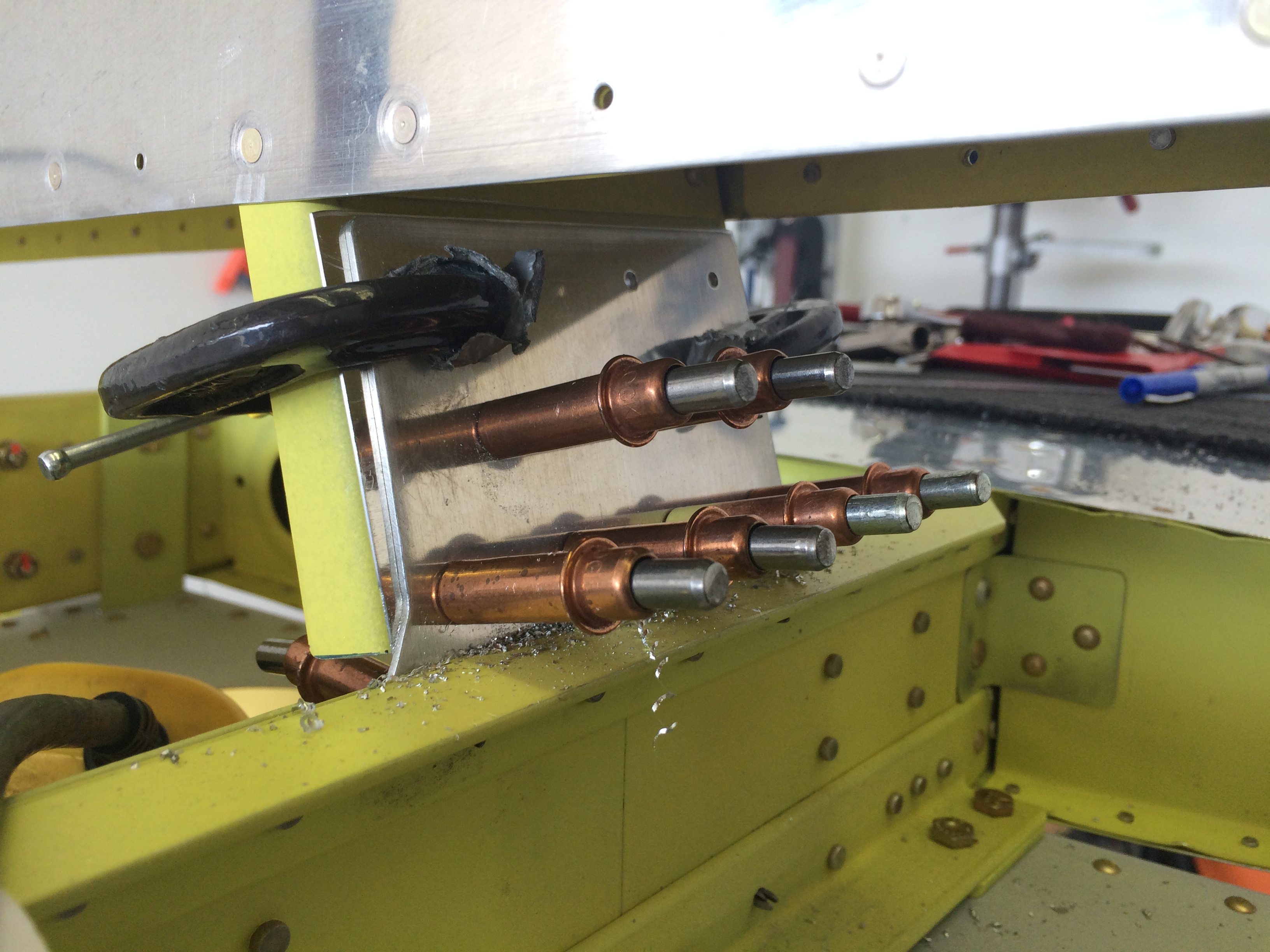
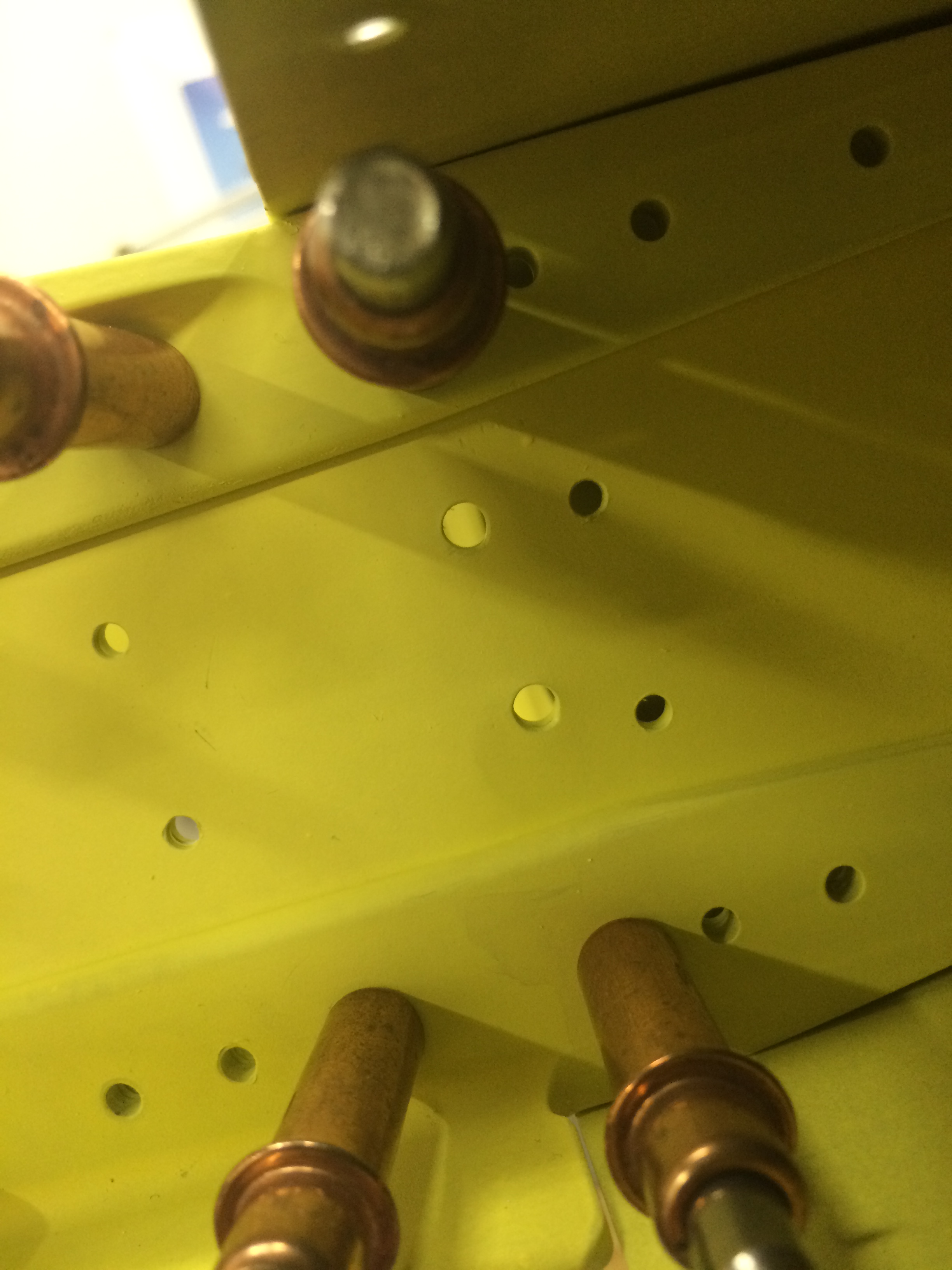
Here I’ve already match-drilled the plate to the horizontal spar – those holes will be opened to #12 – and I’ve started drilling the plate to the vertical spar as well. I had to insert a 0.020″ shim between the plate and spar to improve the fit.  The plans tell you to anticipate this, and have dimensions for fabricating a shim if one is required.

Drilling VS front spar 2

I used the angle drill sparingly on these holes. Some of them didn’t get final-drilled until I removed the vertical stab for priming.

Rear VS attach

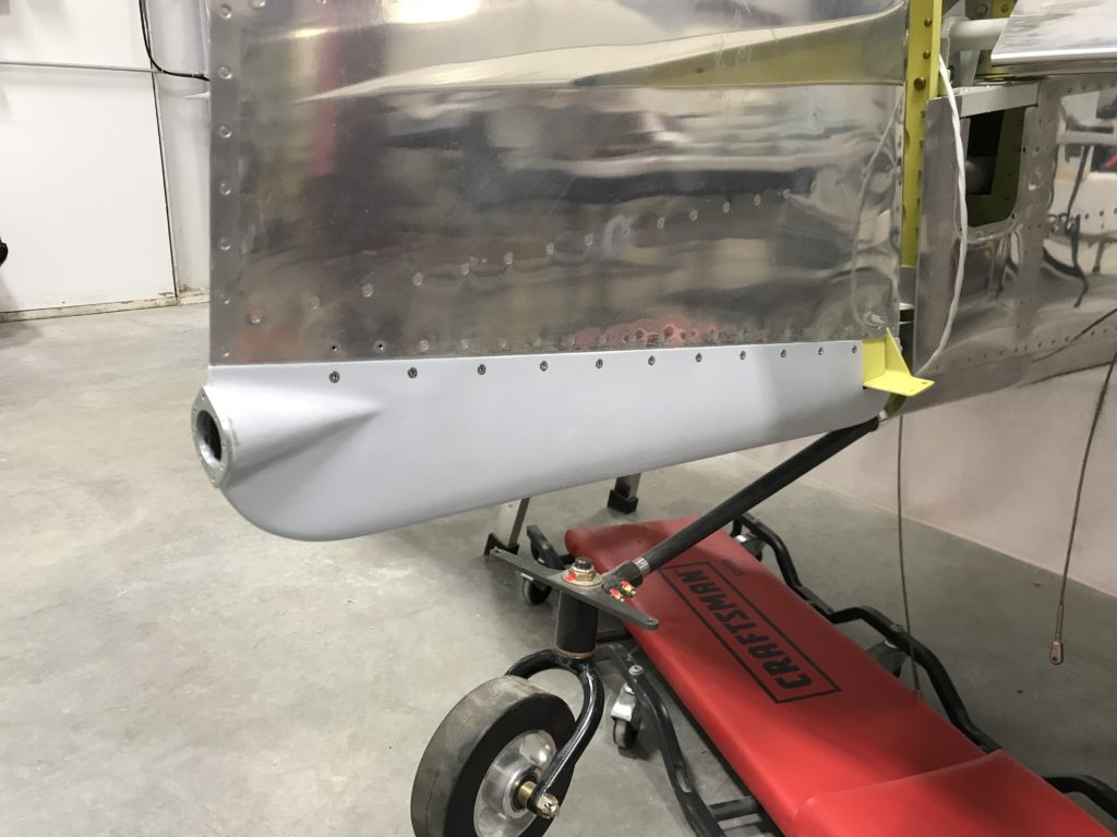
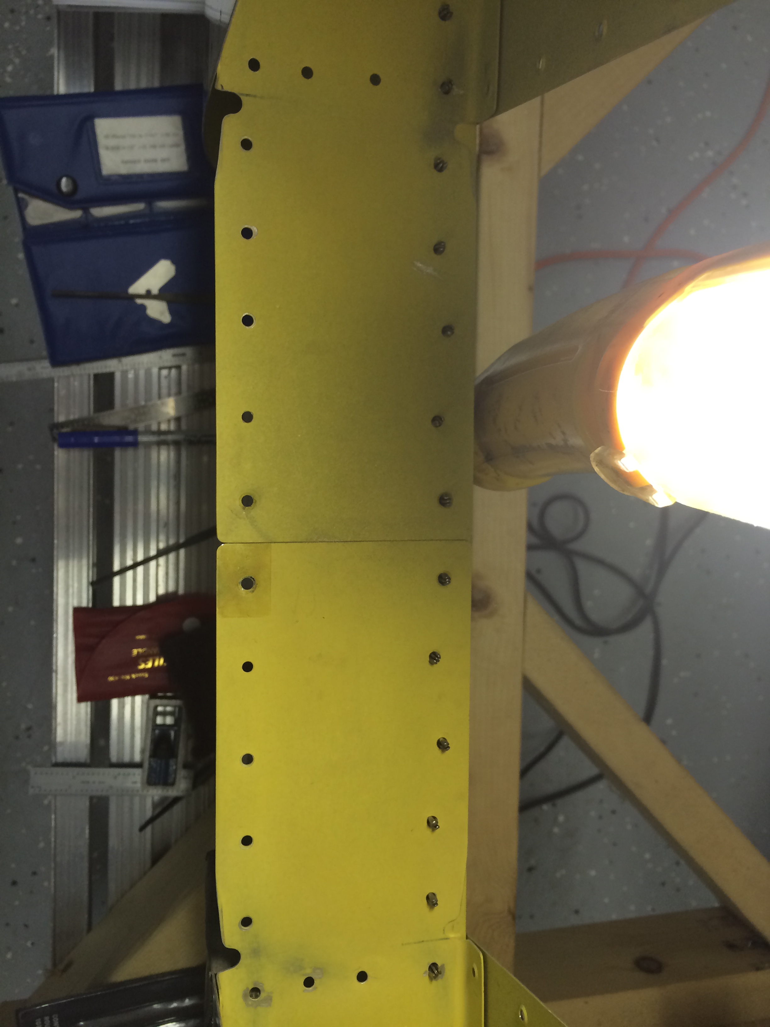
Here’s the vertical stab’s rear spar primed and bolted into place.

Tailwheel fitting bolted and torqued

I neglected to take many pictures of the measurement and drilling process for the lower three bolts – they secure the vertical stab lower spar and tailwheel aft attach bracket to the fuselage.

The measurement process was a little tricky – edge distance has to be maintained on the tailwheel bracket and the vertical stab spar, but they’re on opposite sides of the aft most fuselage bulkhead so it’s impossible to directly measure edge distance. The only way I could get this done correctly was to establish a series of reference points for the tailwheel bracket measured from the fuselage sides and aft deck. Those reference points allowed me to project the location of the tailwheel bracket onto the rear side of the aft fuselage bulkhead.

With the vertical stab clamped into place, I was then able to pick hole locations that met all of Vans edge distance criteria. After that, drilling the holes was a piece of cake.

Tail in place

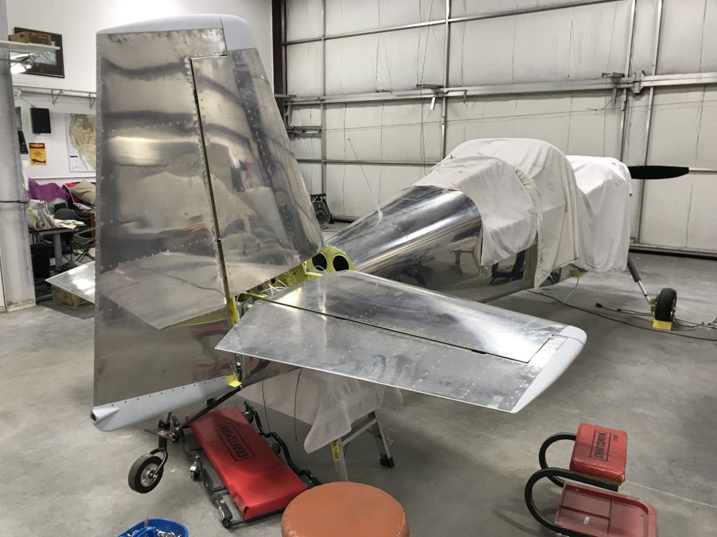
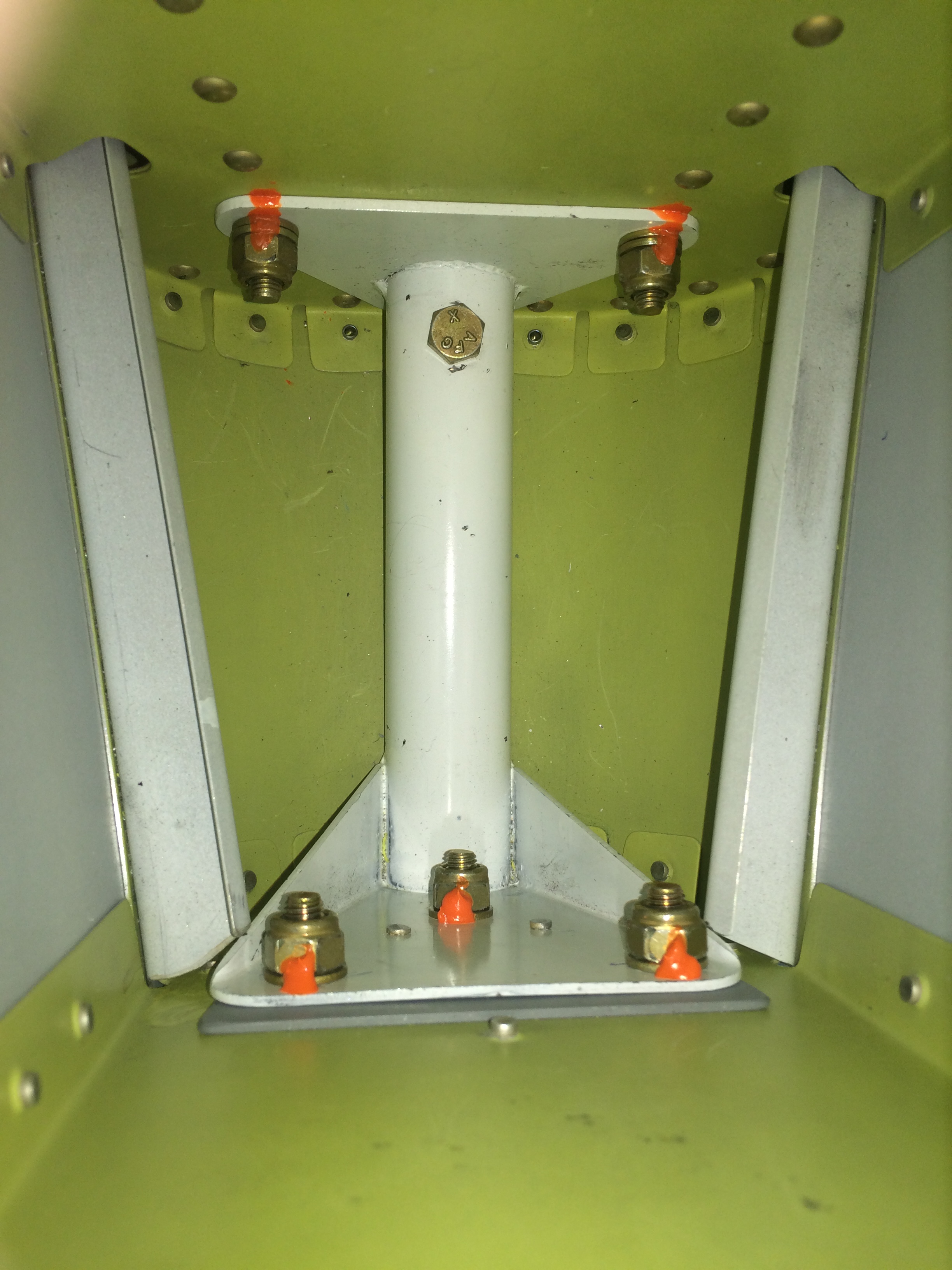
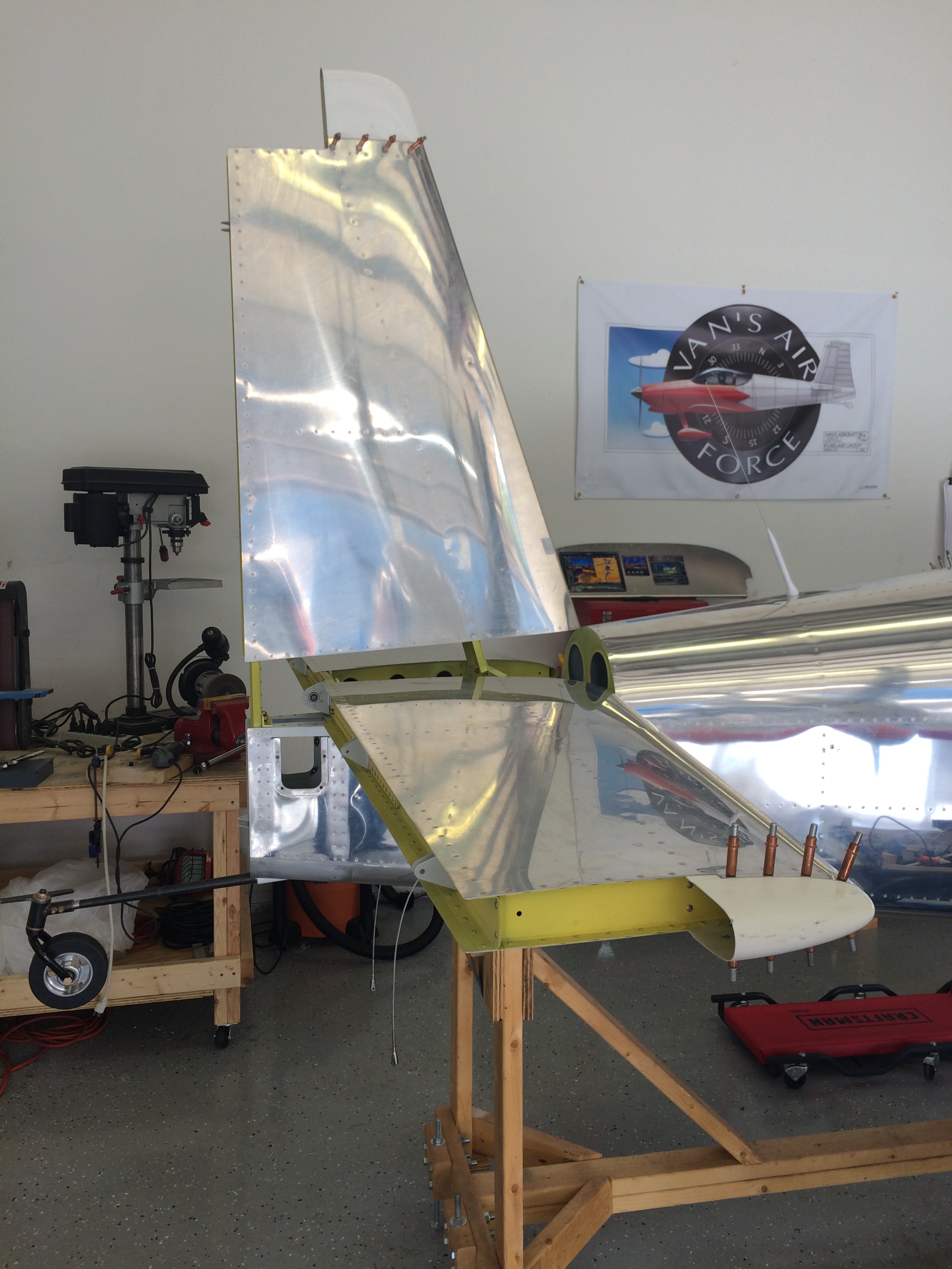
Here’s the vertical stab bolted and torqued into place…very cool.

Tail attached from the rear

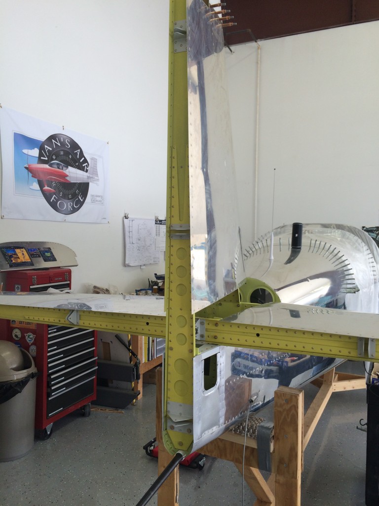
Another pic? Sure, why not…

Nice tail!

And I couldn’t resist temporarily installing the rudder…it’s been waiting a long time to be on the airplane!
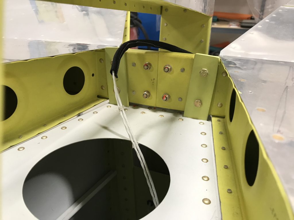
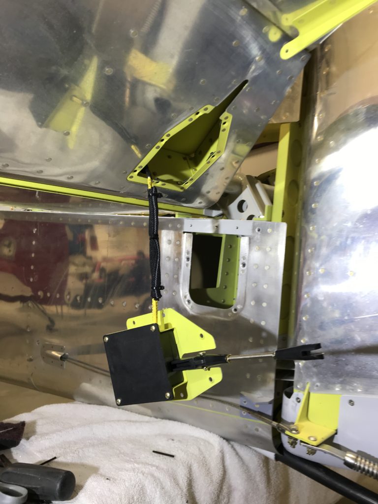
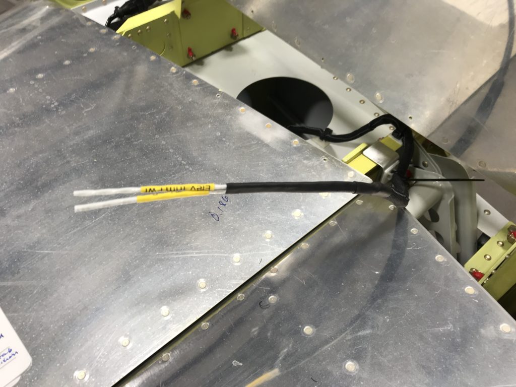
Drilling away at the horizontal stab service bulletin

For the last few months I’ve been chipping away at Van’s horizontal stabilizer service bulletin. This service bulletin addresses cracks found in some the front spar center section web on some RV horizontal stabs.

My stab obviously hasn’t flown yet, but I decided to go ahead with the SB mod anyway. If I screwed up the mod, I’d still have the option of building a new horizontal stab. But once the stab is drilled to the fuselage, I’d be committed to modifying it as it would be very difficult to fit a new stab to mounting holes already drilled in the fuselage.

Working on the HS SB

Drilling out rivets isn’t fun, and drilling out AD4 rivets in a confined space is even less fun. Getting the inboard ribs out wasn’t hard, but drilling out the AN470-AD4 rivets in the front spar was a bitch.

Rivet heads removedHowever, with some patience and persistence, and more importantly some help from Bob DiMeo, I was able to get the heads drilled off of all the hard-to-reach front spar rivets. All that’s left is to punch them out, and start fitting the mod kit.

Rivets punched out

It was tough to punch out the rivets on each end of the angles, but a little patience and persistence won the day.

Front spar

Seems like years since I riveted this structure together…oh, wait – it was years ago, ten years to be precise.

Spar angle

One angle removed…

Trimming front spar flanges

Another tedious task…trimming the upper and lower flange on each side of the front spar. The black line marks the cut line, and Van’s thoughtfully includes a small piece of stainless steel to slide beneath the spar flange to protect the skin while cutting. Following the instructions, I used a small cutoff wheel on my Dremel tool to do the trimming. Gotta be careful using a motorized cutter in this area…

Front spar flanges trimmed

The end result, with some additional polishing to remove some scrapes left from rivet removal. I’ve also enlarged the U-shaped relief notches per the instructions.

Spar doublers drilled 1

After all that work, fitting the doublers was relatively easy. I deburred them, adjusted the bend angle slightly to match the front spar, then drilled them in place. Some care is required to make sure the holes are drilled perpendicularly to the spars, angles and doublers.

Here’s another picture of match-drilling in progress…

Front spar doublers drilled 2

And the end result – doublers ready for priming…

Front spar doubler deburred

I had to do some additional cleanup and prep of the doublers and angles before priming.

Priming front spar partsPriming wasn’t a big deal, just had to keep the hangar warm enough to let the primer cure.

I had to upsize a couple of holes to #20 because

Enlarged holesI encountered one other problem…a line of rivets added for the mod interfered with one of the nose rib flanges. After a quick call to Vans, I decided to cut off and replace the offending flange. You can see in the next picture where the rivets lie relative to the nose rib web after I cut the flange off.

Nose rib flange mod 1Here’s the new one…

New nose web flange

And here’s the final result after priming and riveting the new flange, then riveting the ribs to the skins –

HS mod complete

Officially declaring the horizontal stab to be complete

Lots of things going on at work and at home, so not much progress to write about. I did manage to prep and prime the spar cutout mentioned above, but there are no pictures. Just look at the pic above and imagine that bare aluminum covered with beautiful yellow primer. After that, the center bearing bracket was torqued back into place.

And with this entry, I’m officially declaring the horizontal stab to be complete – at least for now. I’m postponing any fiberglass work for awhile.

HS spar lower flange

HS flanges trimmed

Here’s the cutout on the HS spar lower flange. The plans don’t call out any specific dimensions, so I cut the flange to accomodate the elevator control horns with a 1/8″ clearance on both outboard sides. The flanges were trimmed forward until they were just about flush with the spar stiffeners.

With this cutout, elevator down-travel more than meets Vans’ requirements. Next step…drilling elevator control horns to the HS center bearing.

Sketchy plans

HS skin trimming

The plans are kinda sketchy on how to check elevator fitment on the HS. After some web surfing and questioning other builders, I came to the conclusion that the elevators seem to be fitting ok. The elevator counterweight arms are parallel to the HS skins, and there doesn’t appear to be any binding – yet. With the counterweight arms clamped to the HS, the elevators also appear to be aligned in trail. The control horns don’t quite line up with each other, but from what I can determine from VAFWWW and the Matronics list, they don’t have to.

After the HS skins were trimmed sufficiently to allow the elevators to swing freely, I used a digital level to check elevator range of motion. Looks like the elevators have a few degrees’ margin of up-travel before they contact the HS skins, and according to Van’s there is no minimum spacing requirement between the elevator skins and HS. So as long as they swing freely, I think I’m good to go. If you’re reading this and know something different, please don’t hesitate to email me!

The next step is to trim some HS flange material away to allow the elevator control arms to reach maximum down-travel. I debated doing this before riveting the HS spar together, and now wish that I had. Some substantial care will now be required to avoid damaging the spar stiffeners.

Temporarily mounted the elevators

Elevators mounted

Ellen and I dusted off the horizontal stab and temporarily mounted the elevators. The rod end bearings in both elevators required some tweaking to get their centers 13/16″ from the elevator spar webs, but that turned out to be no problem. As noted in the plans, some HS skin trimming is required to get the elevator counterweight arms to swing freely.