Rolling my own…

…Nav antenna, that is. I had always planned on using a Bob Archer-designed wingtip Nav antenna because they work well for horizontally-polarized ILS/LOC/GS signals and also fit nicely within the wingtip fairings, thus eliminating a tiny bit of parasitic drag. You can find Bob Archer’s description of his antennas here and instruction/plans for building them here on Van’s Air Force.

I was all set to buy one of Bob’s antennas from Aircraft Spruce. But since I’m an Electrical Engineer by education (can’t spell “geek” without EE) as well as an airplane homebuilder and ham radio operator (N1DLS), I decided to make my own antenna out of some materials I had laying around the shop and a piece of fiber/resin circuit board material I bought from McMaster Carr.

There’s nothing difficult about fabricating the antenna, it’s only an afternoon’s work to put one together using plans you’ll find on the interwebs.

Home-rolled Archer antenna

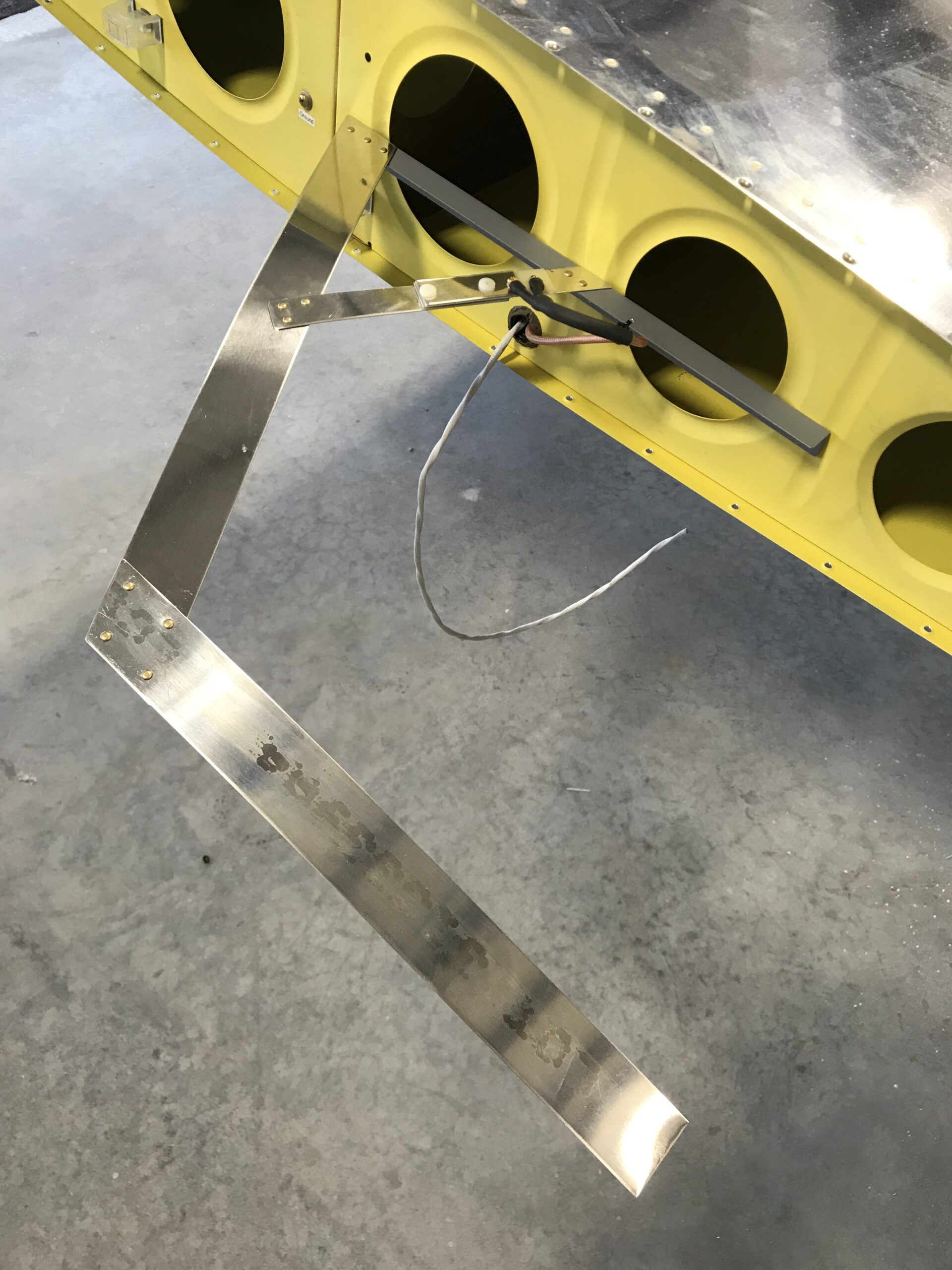
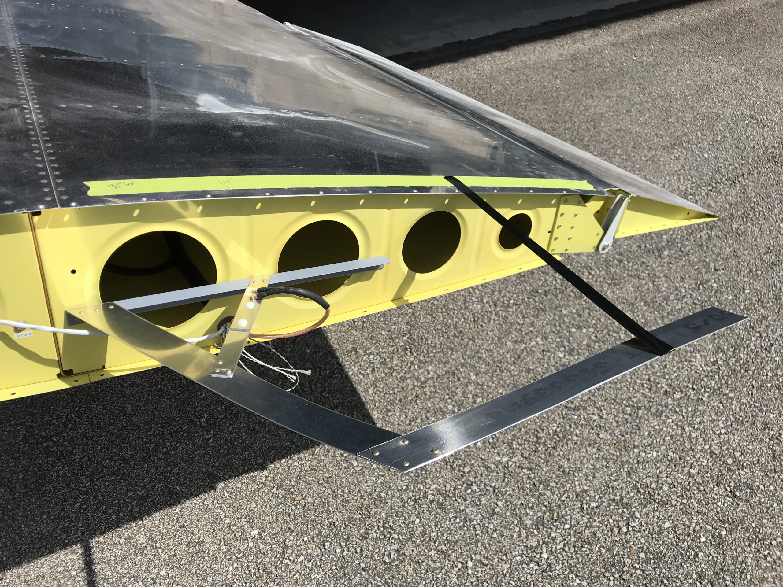
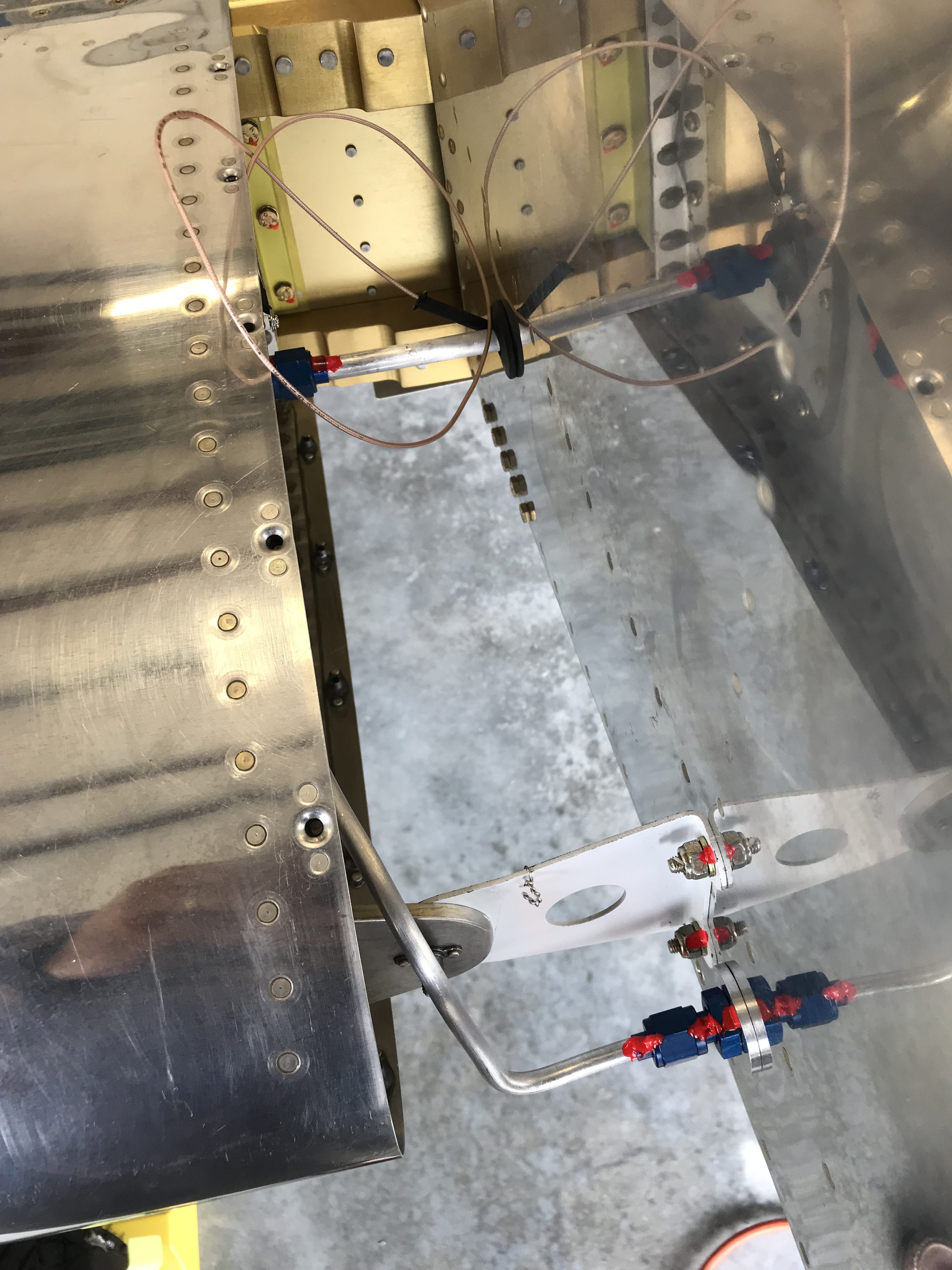
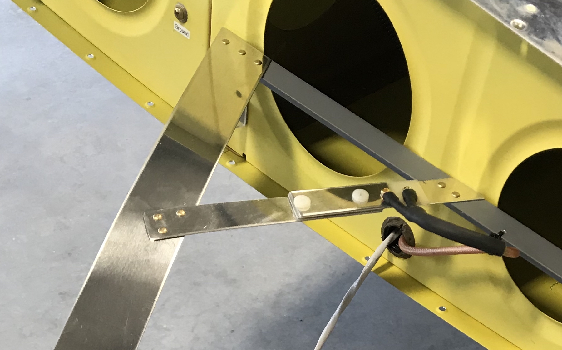
The magic in this antenna lies in a couple of areas – the gamma-match coax impedance-matching device, which is the narrow aluminum and fiberglass structure to which the coax connects, and the length of the long outboard aluminum strip that’s parallel to the wing. The antenna must also be well-grounded to the aircraft, hence the big piece of aluminum angle that holds it onto the wing.

Archer Gamna

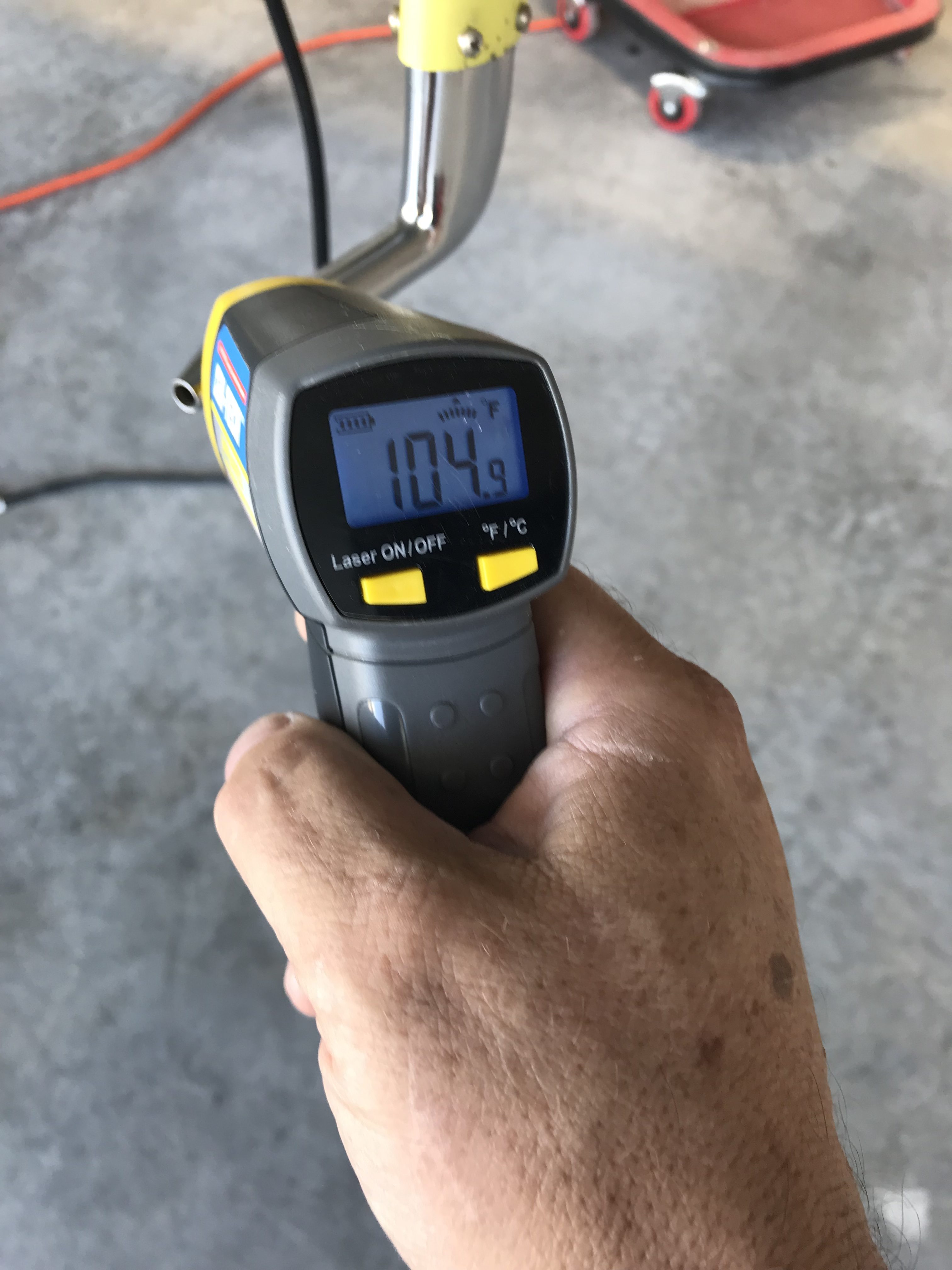
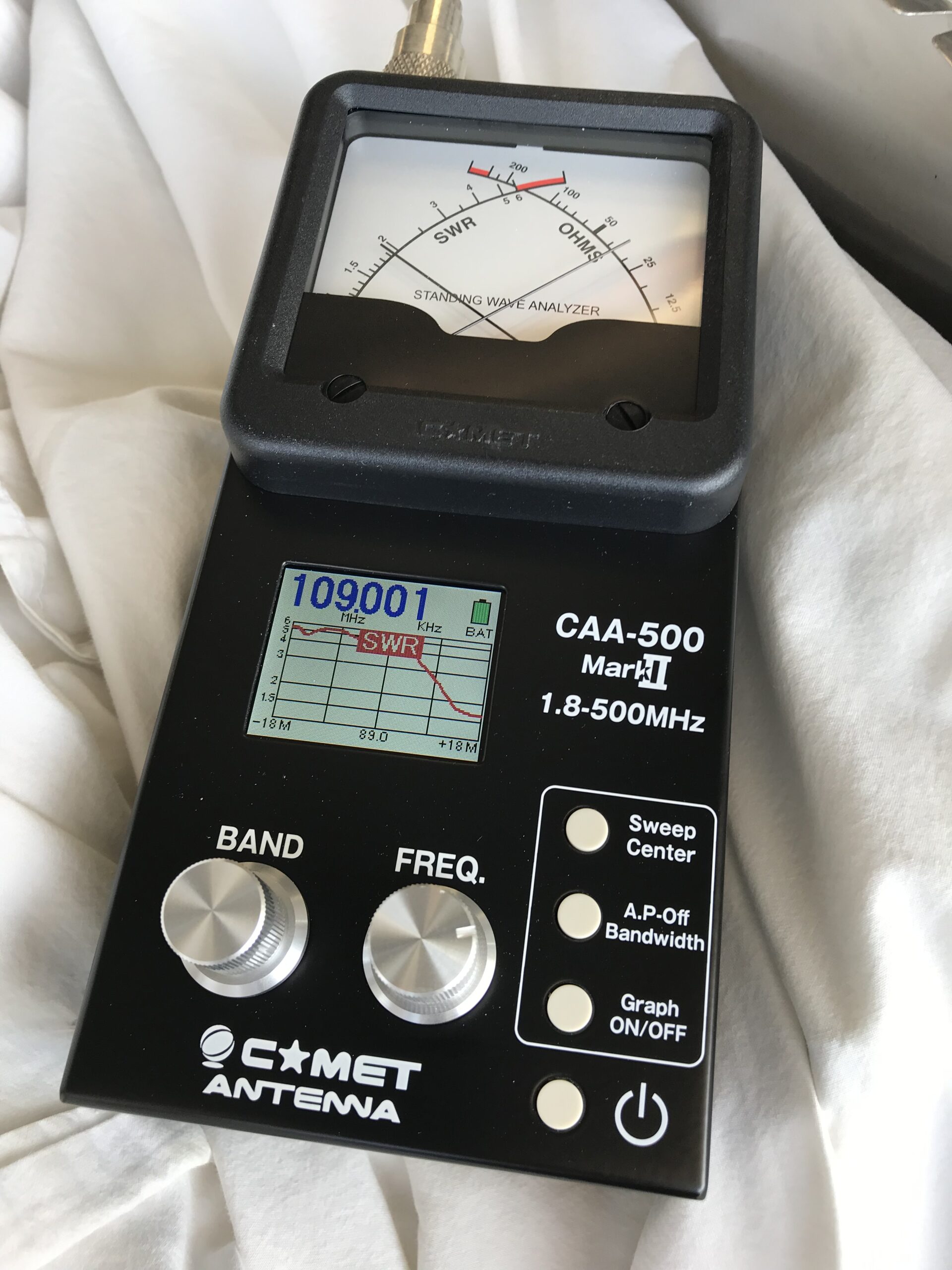
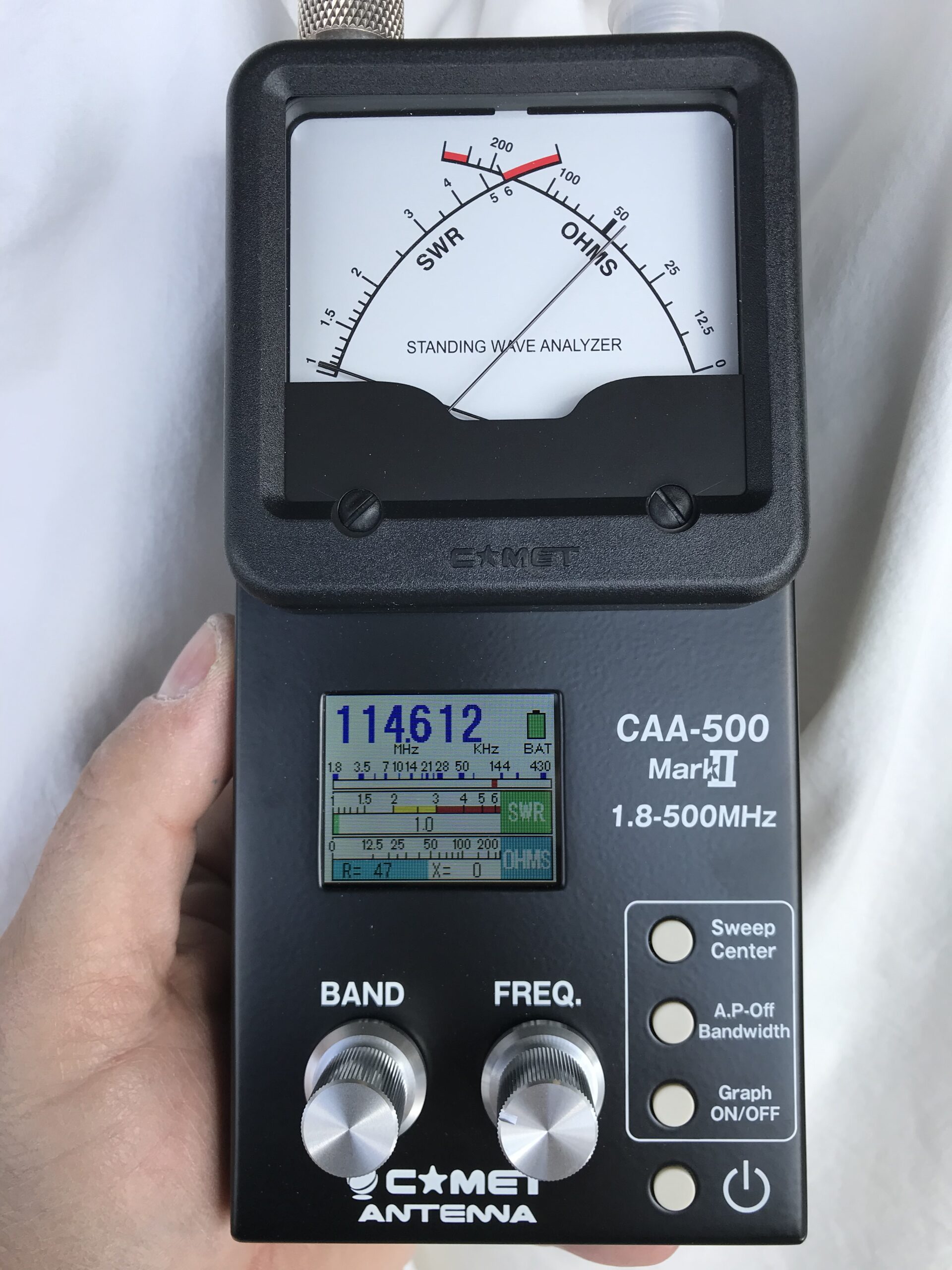
So how does the novice Archer antenna builder know how to adjust these magic bits? The answer is an antenna analyzer, something which no self-respecting ham radio nerd would be without. Here’s mine –

Antenna analyzer #1

The instructions should tell you how to tune the antenna but if you need help and an antenna analyzer as well, hit up your nearest airplane-building ham radio buddy (there are a lot of us) and he/she/I will be glad to help.

After several iterations of adjusting the gamma match and antenna length, I had a well-tuned and matched antenna…I hope. The analyzer picture below shows that the antenna is almost perfectly matched at 114 MHz. I can live with that.

Analyzer with matched antenna

And here’s the final product –

Final Archer antenna

Wiring and plumbing the wings

We’re getting close to Oshkosh and I wanted to get as much done as I could before our trip, so over the weekend I installed the pitot tube and wired landing lights, OAT probe and pitot heat to their circuits in the fuselage.

Here are the Baja Designs Squadron Pro landing lights connected and doing their thing. Not terribly bright in this picture but they hurt to look at, and that’s a good thing…

Landing lights

No post on landing light installation would be complete without proof that the GAD-27 can indeed flash the lights…

I had fitted and plumbed the pitot tube several years ago so installation was relatively straightforward – just had to connect the AN plumbing and heater connector, then screw it to the pitot mast. And yes indeed, it gets hot…

Heatet pitot is hot!I screwed up the fuel tank feed lines, so some surgery was required to install an AN union and line to the left fuel tank. Once that was done, I reinstalled the vent line I fabricated a few years back. The RG-316 coax you see snaking out from the rubber gasket is a line that connects a Princeton capacitive fuel level sender to the fuel tank’s BNC connector.

Left fuel tank plumbed

Same thing on the right wing…

Right fuel tank plumbedPlumbed the right wing as well, and installed the fuel tank support bolts on both sides.

Pitot-static and OAT connected

Connected the OAT probe and pitot-static lines in the cockpit.

More right wing plumbing…and finished connecting the right fuel tank. Had to do another splice job on the fuel line, but it came out fine.

And now we’re off to Oshkosh!

Back to the wings

I’m working on preparing the wings for final installation, and one task that’s easier to perform now is installation of the Garmin GSA-28 autopilot roll servo. Nothing too tricky here, the G3x installation manual covers the process nicely. I’ve had this servo sitting around for a couple of years and it took a bit of searching to find the necessary parts.

Roll servo mostly installedOne gotcha…in the past, Garmin claimed that their servo was compatible with mounting brackets from other manufacturers but that turned out not to be the case. I had originally installed an Advanced/Dynon servo bracket, because way back when I built the wings I was planning to use their avionics.

Turns out that the Garmin servo *isn’t* compatible with Dynon’s brackets, so I had to swap it for the one from the GSA-28 install kit. This won’t be a big deal for anyone who’s installing a servo from scratch, but if you’re swapping from another manufacturer, be prepared for a little extra work.

Full flaps

Continuing on with avionics and cockpit wrap-up, I had to install a microswitch that tells the angle-of-attack (AoA) computer when the flaps are down. Flap deployment changes the coefficient-of-lift curve and so for the AoA computer to work properly, it needs to know when the flaps are down.

Where the flap-down switch resides

The only place I could think of for the switch was right at the front of the flap arm, which is at its lowest point when the flaps are up. I thought I’d do something really spiffy and adjustable…

Flap-down switch, first attempt

…but that didn’t work so well because the bracket (dark grey thing with the black switch attached) was too long and interfered with the elevator pushrod.

Flap-down switch finalGoing back to the drawing board, I put a 90-degree bend in the bracket and rotated the switch so that it’s activated by the flap arm clevis. Works great, and there’s enough play in the switch that I can adjust it later if necessary.

Turns out that was the easy part. This switch grounds a wire coming from the AoA computer, so I had to run a wire from it to the central ground block in the elevator pushrod tunnel. That took most of an evening, but it’s done and the AoA computer now shouts “flaps” through the intercom when the flap-down motor is activated.

Flap motor installed

And here’s the installed flap motor with a Deutsch DTM connector all ready for plugging in to flap power and position sensor inputs for the GEA-24 and GAD-27.

Trimming the starboard stabilizing ailertooters

I have an unfortunate tendency to communicate in movie quotes, so bonus points to you if you can identify the “starboard stabilizing ailertooter” reference without using Google, Bing or some other internet search megalith.

No, the Mighty RV doesn’t have ailertooters but it does have ailerons and that’s what prompted the title. One of the last bits of cockpit work is installing the aileron trim motor; I fitted the bracket way back when I was building the fuselage center section and all that was left was to install the motor and connect it to the flight controls.

Aileron trim installed

I didn’t take any in-process pictures, so all you get to see is the final product. The trim motor is under the square white bracket in the lower center of this picture. It drives a lever that’s connected to the control sticks with springs which are adjusted to be in just enough tension that the motor can move the sticks but not significantly affect roll control feel.

Drawing current

So after finishing almost all of the avionics wiring, I came across a little warning in the Garmin installation manual that their engine monitor unit may not be able to provide enough current to the boxes that determine the amount of fuel in the tanks – a bit of potential non-coolness. But I have a piece of parchment on the wall that says I know something about electrical engineering, so I decided to run a quick to check on Garmin’s warning.

Measuring fuel sender current

I popped the fuel level sender’s Deutsch connector apart, jumpered my multimeter into the power line and powered up the avionics. Voila…an accurate measurement of the sender’s current draw – 8 mA, which is significantly under the engine monitor’s max current level. Cool.

First RF

New telescopes have “first light”, the Mighty RV’s avionics had “first RF” today.

Pulling out for a clear view of the skyI powered up the panel – both GPS receivers came up in 3D differential, Sirius/XM is begging for a subscription, tower and ATIS on the comm radios, and there’s even ADS-B In traffic on the G3x to boot. Cool.

First RF

Buttoning up the turtledeck

The tailcone avionics and electrical wiring are done and I really want to rivet the fuselage “turtledeck” skin – the one behind the cockpit. But I also don’t want to dive back there to fix wiring problems once it’s in place.

I’ve smoke-checked the ELT’s RS-232 data connection to the GTN-650, the tail nav/strobe light and even the elevator trim servo. But the last bit to be checked is the servo’s position indicator and the only way to know for sure is to configure the G3x Touch display to read and display position indicator signals. So that’s what I did.

G3x Pitch Trim 1

Configuring the Touch was a lot easier than I feared. All that’s required is to move the trim servo to full up, center, and full down and tell the display when the servo is positioned at each point.

G3x Pitch Trim 2

The Touch calibration page reads voltage coming from the position indicator and displays a gauge preview…very cool. That’s a good confirmation that the tailcone wiring is fully functional.

G3x Pitch Trim 3

And now Elevator Trim shows on the PFD…even more cool!

Turtledeck ready for riveting

A few more minutes and the turtledeck is clecoed into place for the last time and we’re ready to break out the rivet gun and bucking bars.

Current progress

One of the cool things about this stage of the project is that after a few hours of wiring I can turn on some part of the RV’s avionics and see it work.

For instance, I’ve had these Oplite 6 LED lights for several years now and finally got them wired up to the Garmin GAD-27 as instrument panel lights, so they’re controllable by a dimmer on the panel. These lights are really rugged and when driven by one of the GAD-27’s PWM lighting controllers, they’re dead quiet too – no hash on the radio like I’ve encountered with some other dimmers. Very cool.

Panel lights

I’ve also had Whelen LED nav/strobe lights sitting around for a few years, waiting for installation. The tail nav/strobe is finally wired through to the cockpit, and here’s some video to show how damn bright they are…low current draw too, and no need for a heavy strobe pack like older nav/strobe lighting systems.

Next on the list was wiring the flap motor, but I need some hardware to fabricate a mounting bracket. So, I jumped ahead to wiring the Advanced Flight Systems Angle-of-Attack (AoA) system. This is the only “legacy” avionics system on the airplane, as Advanced doesn’t sell it anymore. I hope it doesn’t fail.

For those of you who aren’t into aerodynamics, AoA is the angle at which the wing meets oncoming air, thus generating lift. If AoA exceeds a certain value, the wing stalls and lift is drastically reduced – so you can see why knowing AoA might be important for staying in the air. If you’re really into the concept, watch this video.

AoA is alive!

Everything lights up, and the self-test lady says the system is working…

Of course with all the gee-whiz stuff lit up, I had to take a picture. Enjoy!

A thing of beauty