Food can be effective bribe. Last weekend I bribed Ellen and Whitney, and RV-7 friends Andy Olech and Allison Bailey, with lunch at the Midfield Cafe to help install the wings for the first time. Thanks Andy and Allison, we appreciate you flying up from Hartford and spending the day with us!
And as always, thanks to my family – Ellen and Whits, I couldn’t do any of this without you !
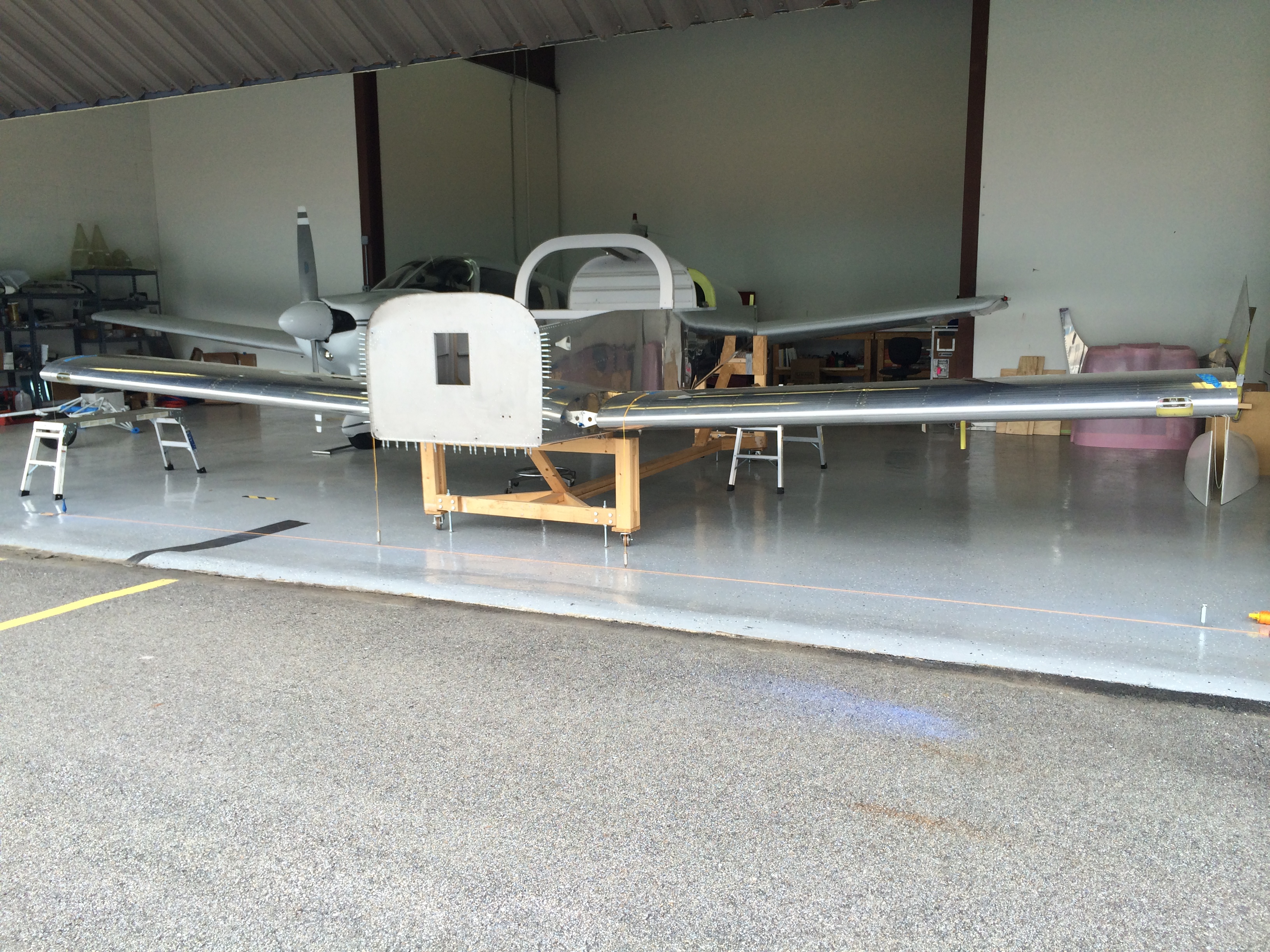
 This is one of those times in the project when a lot of past effort to maintain tight tolerances really pays off. Every RV slow-builder stresses about making sure the front and rear spar bulkhead halves in the fuselage are spaced 1.438″ apart as required by the plans. With the help of a little Boelube, the spar ends slid right into the fuselage. Cool.
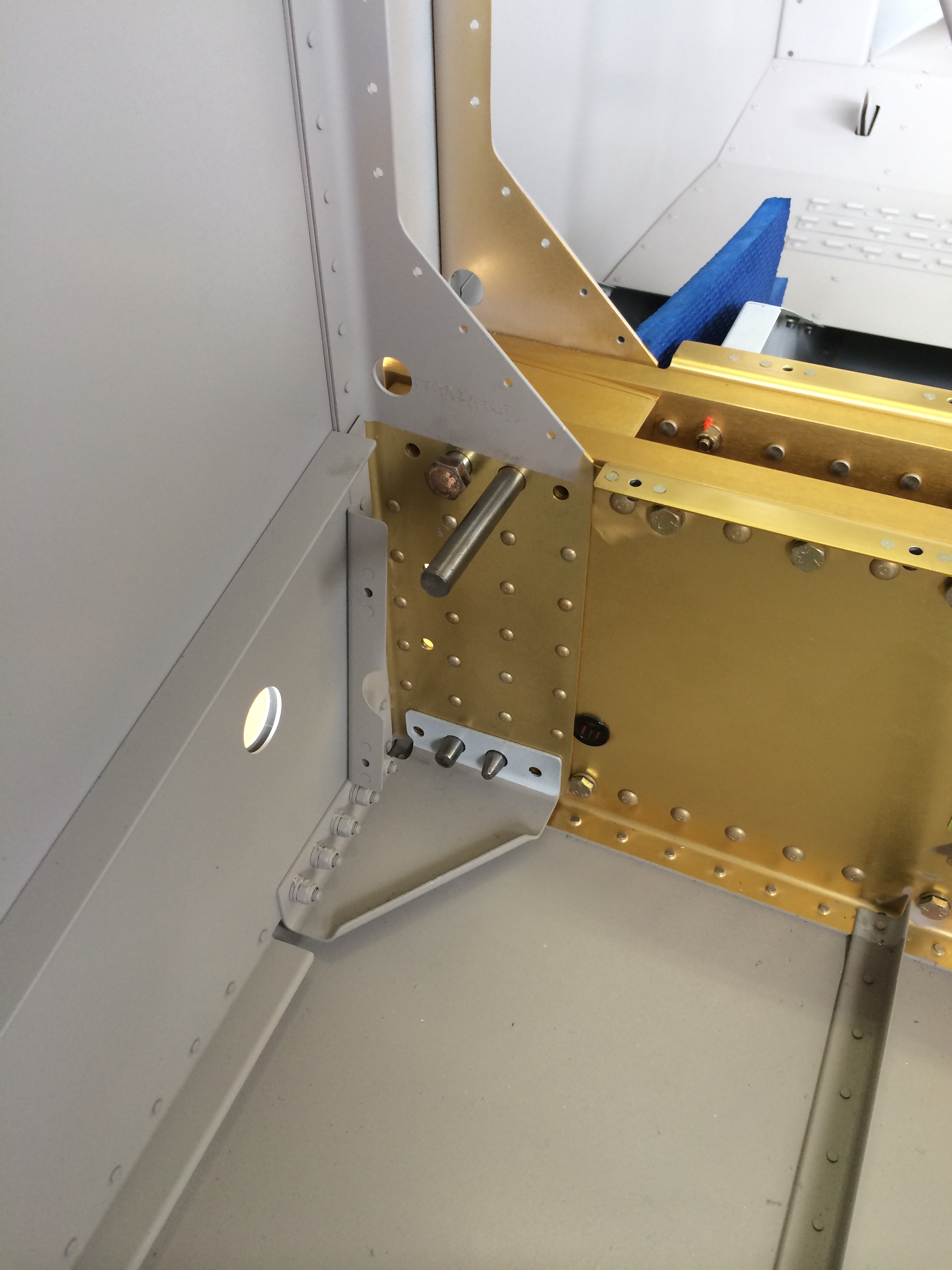
With Andy, Allison, Ellen and Whitney adjusting wing position, I inserted a couple of taper pins into bolt holes for each wing. Van’s calls for four pins, so before I made any final measurements and drilled any holes, I borrowed some long, custom-made stainless steel taper pins to augment the four pins I made from hardware-store bolts.

Thanks to Rich Mileika for making those really nice stainless steel taper pins, to John Sannizzaro and Bill Higgins for flying up to Nashua yesterday and helping me get the last 3-4 taper pins in so that the wings are secure, and last but certainly not least, thanks to Bob Weldon and his daughter Emma for muscle power and precision plumb bob stabilization <g>.
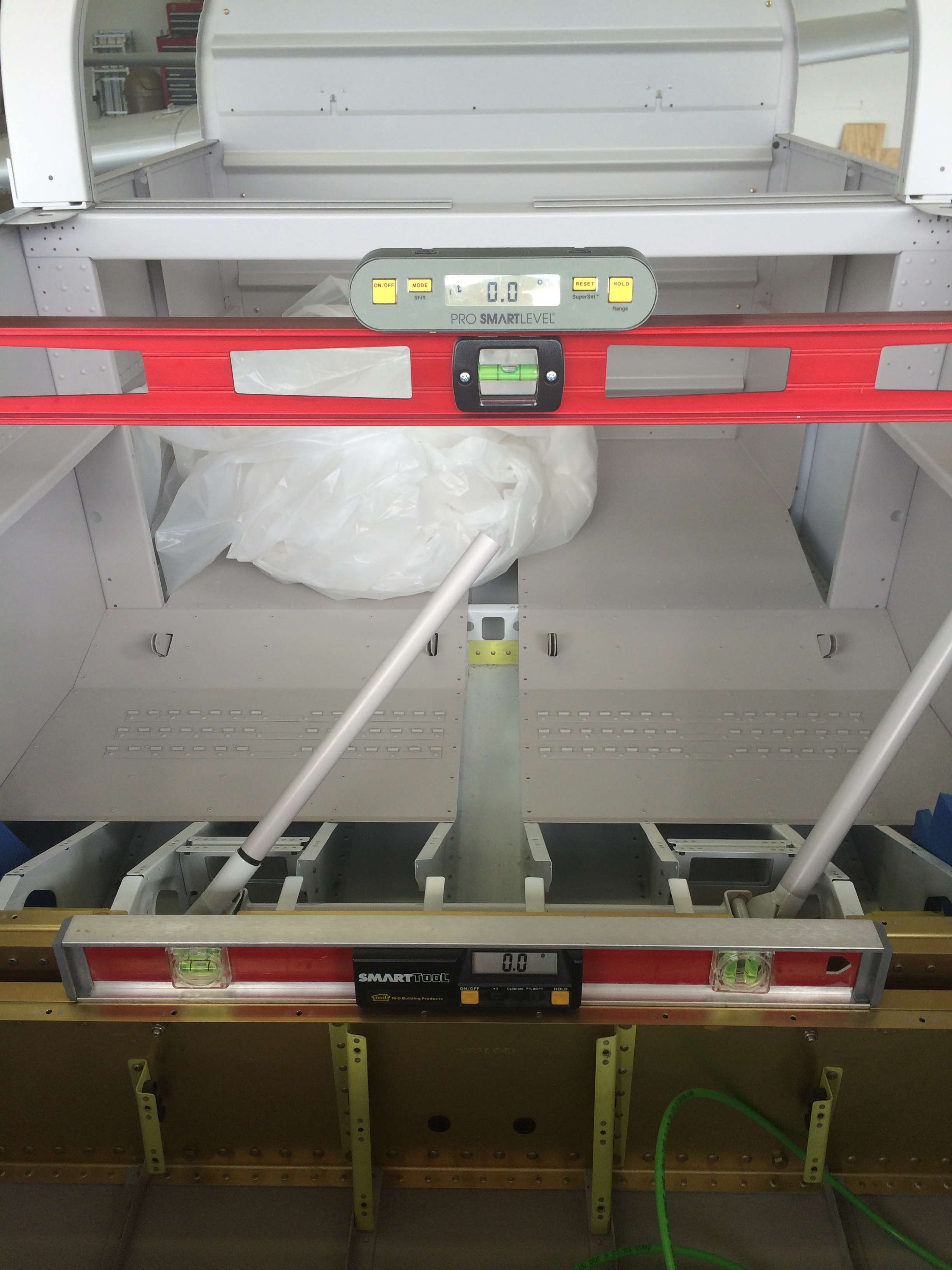
With the wings temporarily installed, I made sure the fuselage was level laterally and longitudinally. The plans call for measuring longitudinal level on the longerons at the cockpit, but these almost always have some residual twist from the bending process that makes it hard to get a good level measurement.
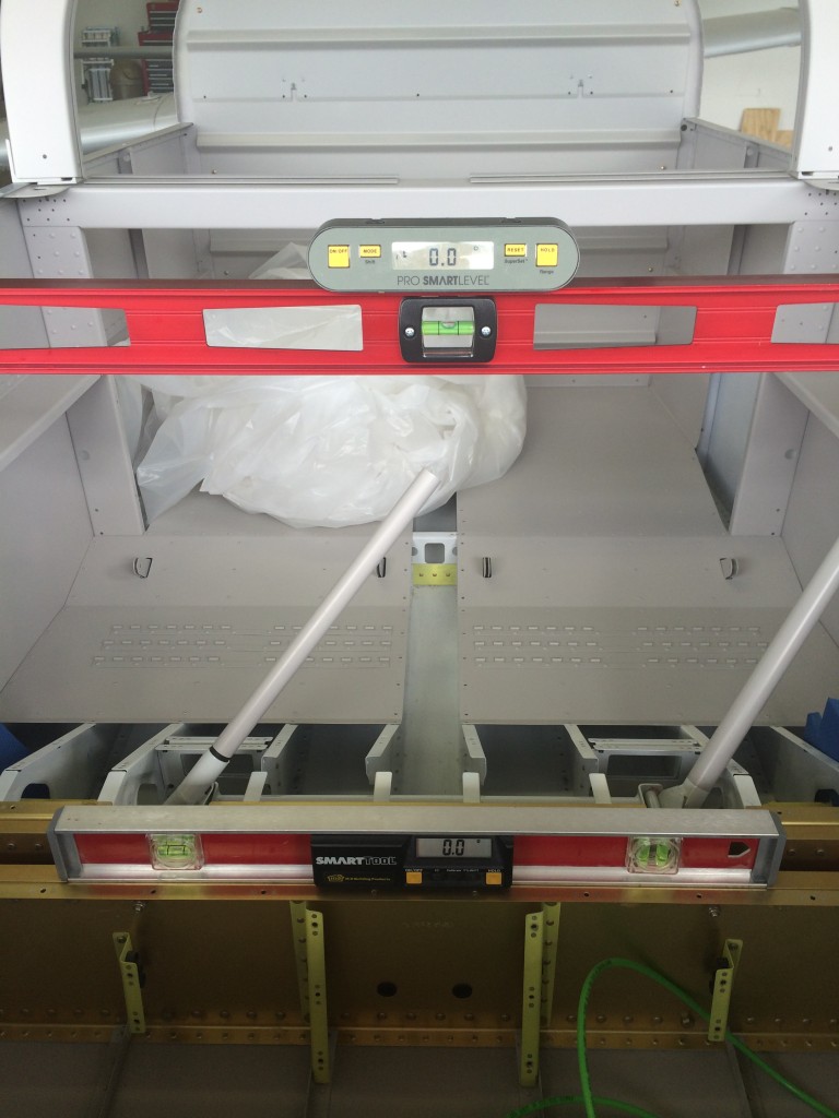 So, I just moved the levels back a few feet to a straight portion of the longerons. I had to adjust the cradle a little to get everything spot on, no big deal.

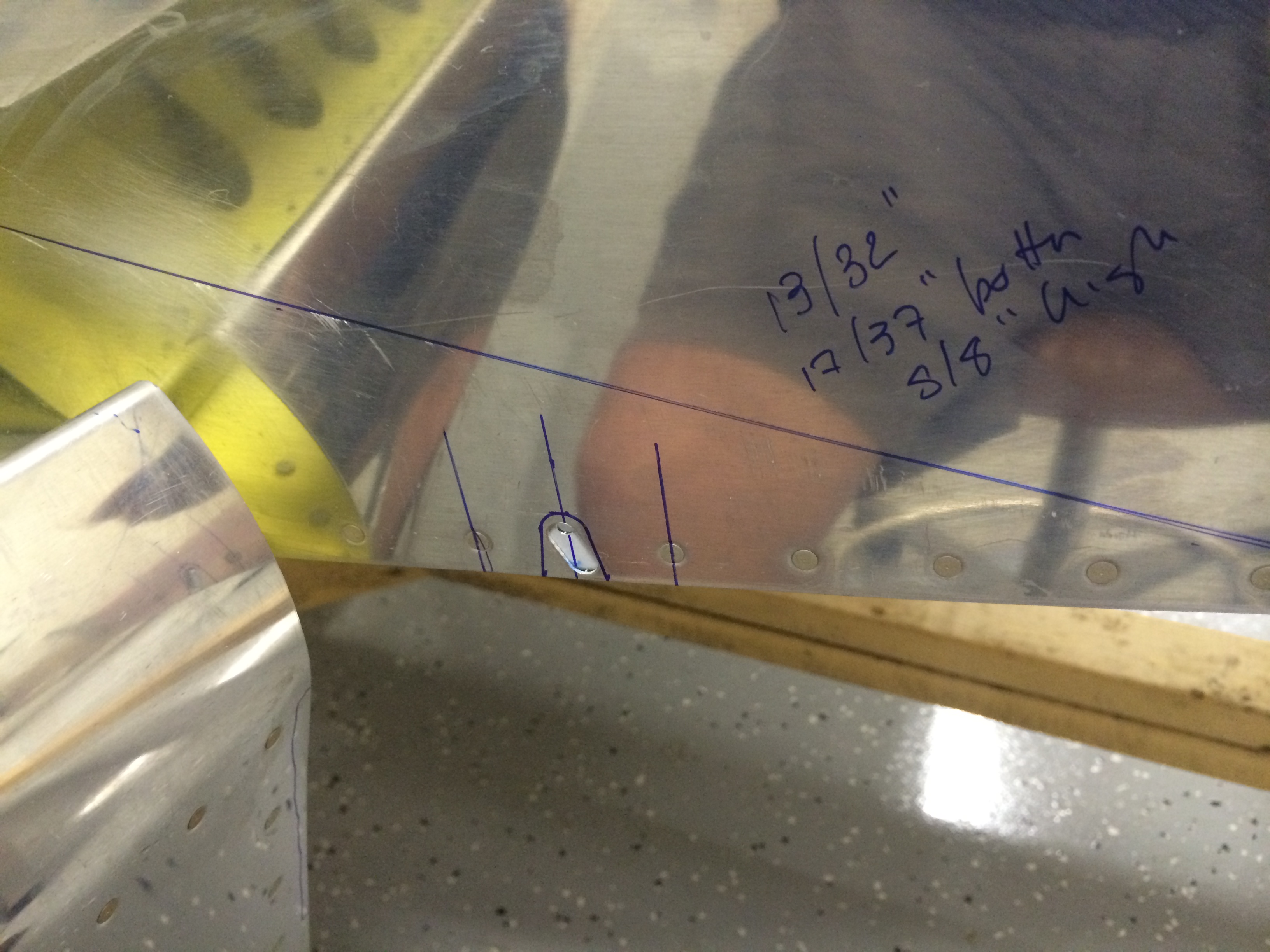
According to the Van’s FAQ on wing incidence and sweep, the next measurement is from reference points on each wingtip to a common point on the aft fuselage. My measurements were the same to within 1/32″…cool again.
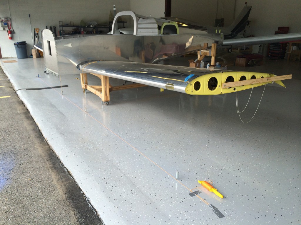
I then dropped plumb bobs from the wing leading edges – one inboard and one outboard on each wing panel, and laid out a reference line between the outboard plumb bobs to serve as a reference for double-checking sweep. Measuring the distance from the inboard plumb bobs to the reference line, I found that each wing had only 7/32″ of sweep, well within the 1/2″ tolerance that Van’s suggests.
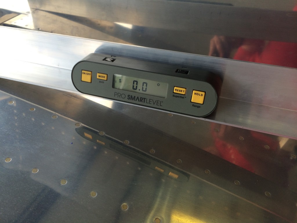
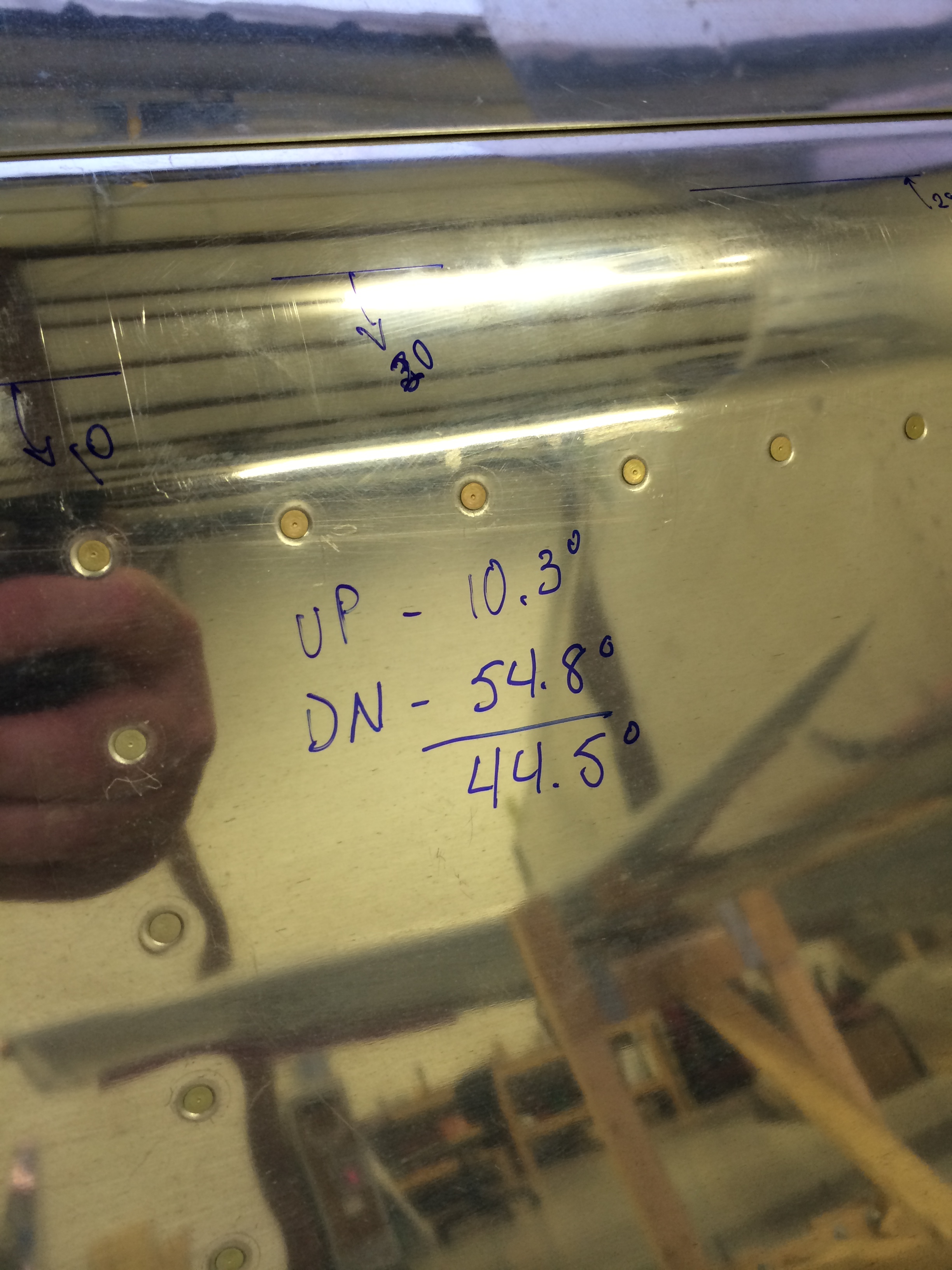
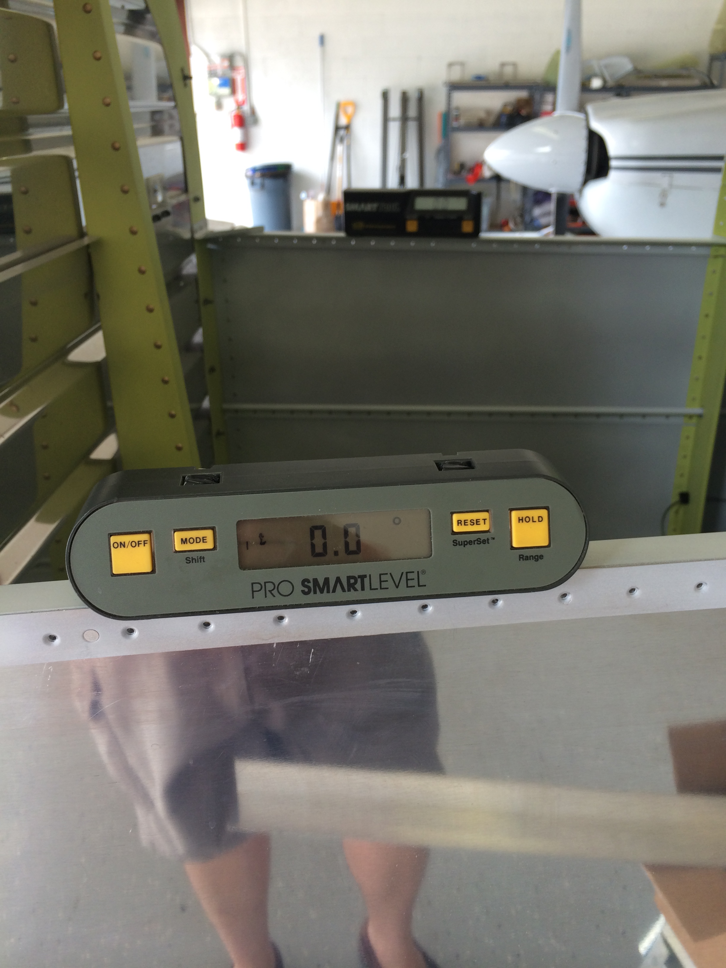
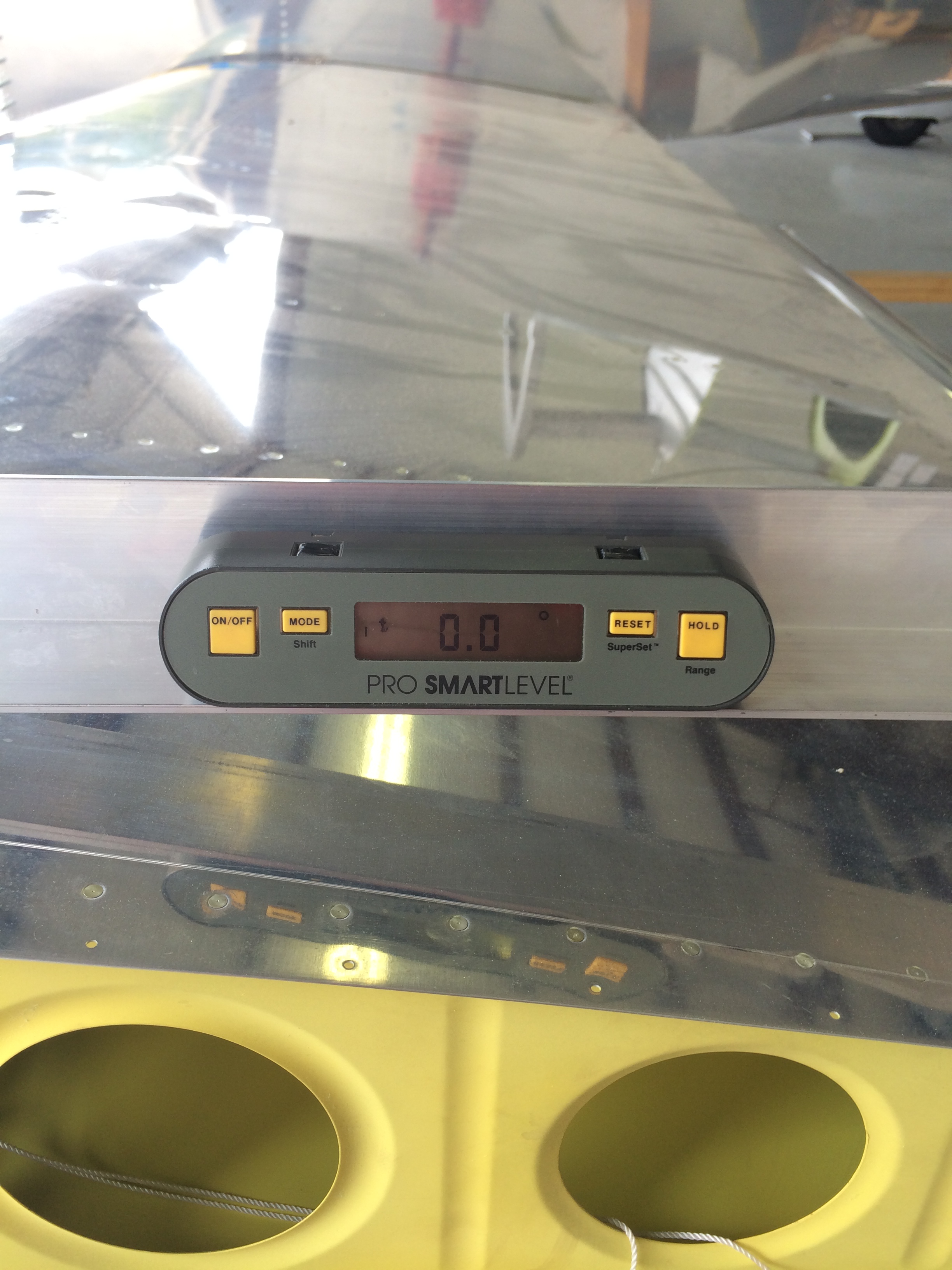
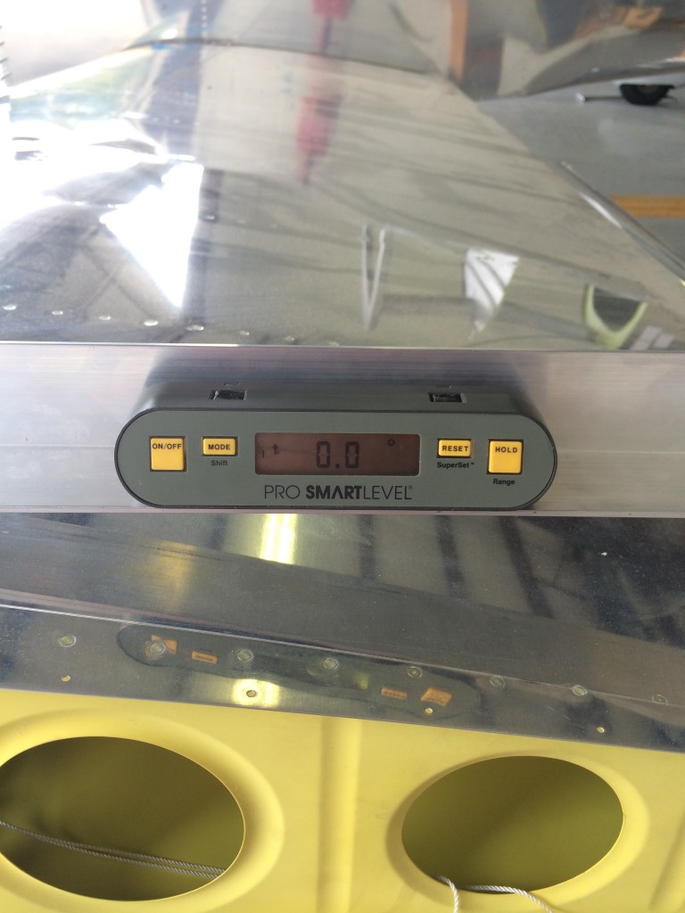
The next measurements check wing angle of incidence. This requires making a simple tool – a carpenter’s level or metal channel with a 3″ spacer on one end. The flat end is placed on the wing skin above the main spar web, and the spacer sits on the skin above the aft spar web. When a level placed on the tool reads zero, the wing has a 1 degree angle of incidence.
The pic above shows the left wing incidence is right on the money. The right wing was the same.
Just for a goof, I checked the angle of incidence at each wingtip…every measurement was within 0.1 degree. This is a real tribute to the quality of Van’s prepunched kits; with reasonable effort, it’s possible to build a nice, straight airplane.
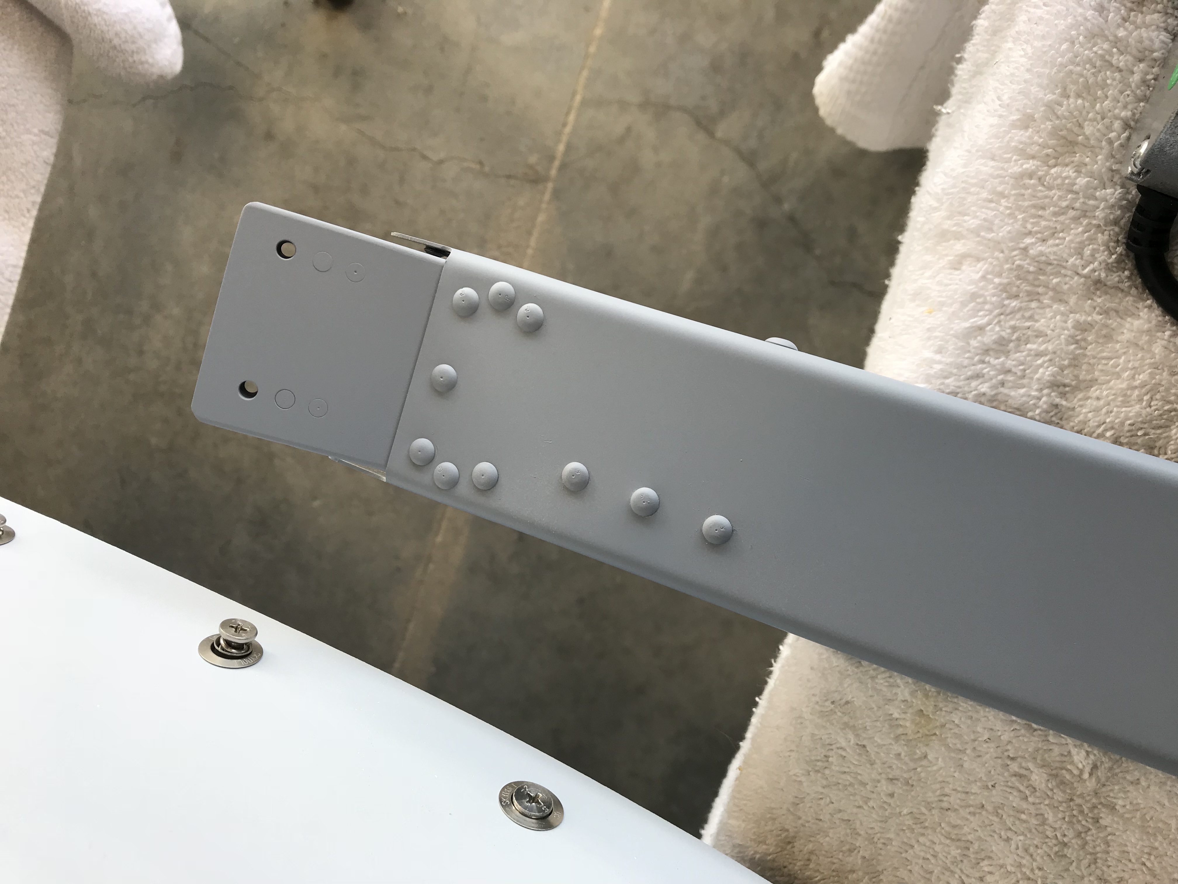
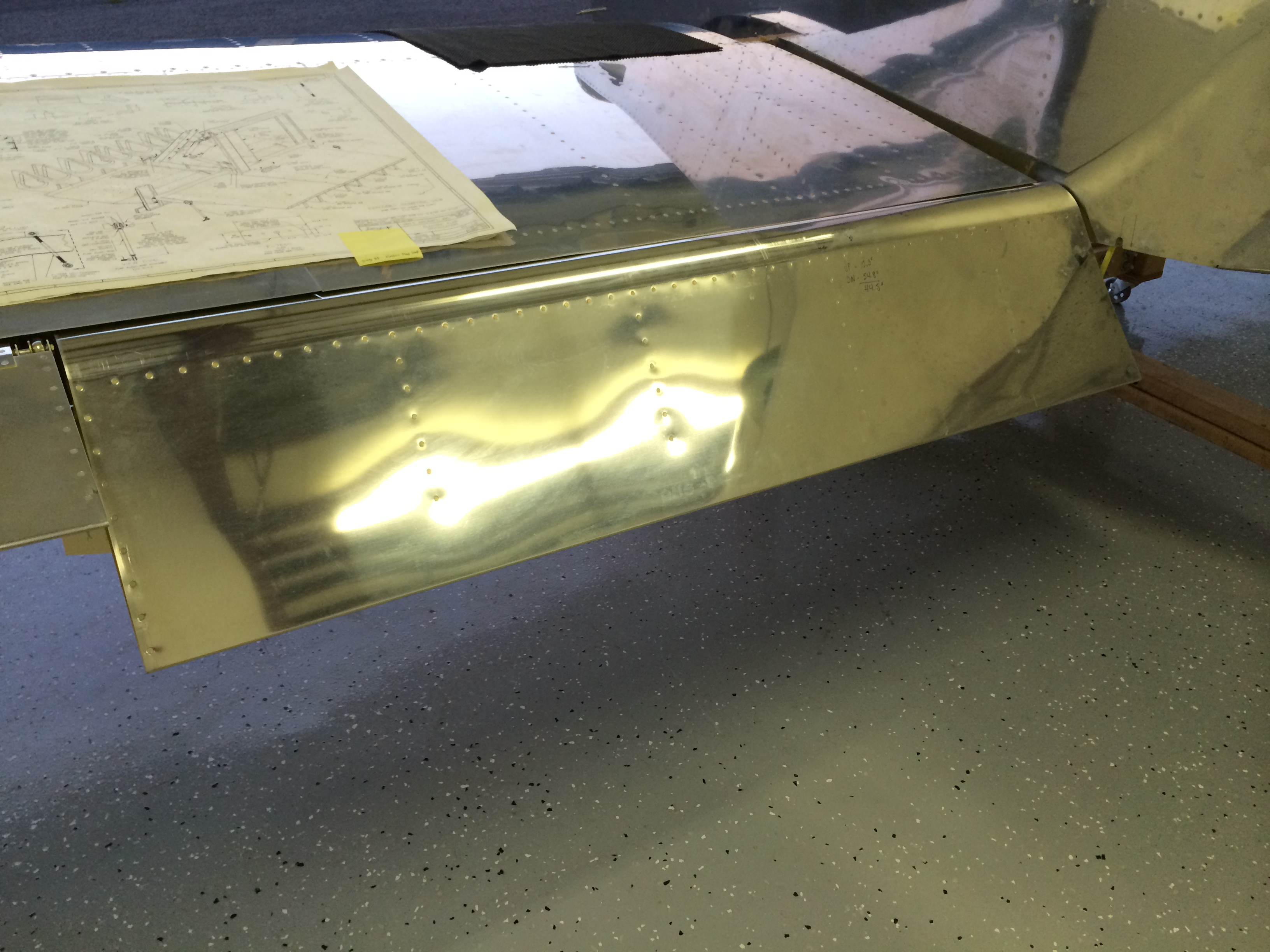
I also test-fitted the flaps to make sure the inboard flap skins fit nicely against the fuselage…
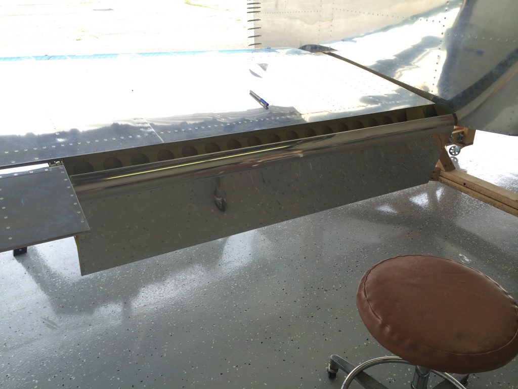
…and it looks like they do.
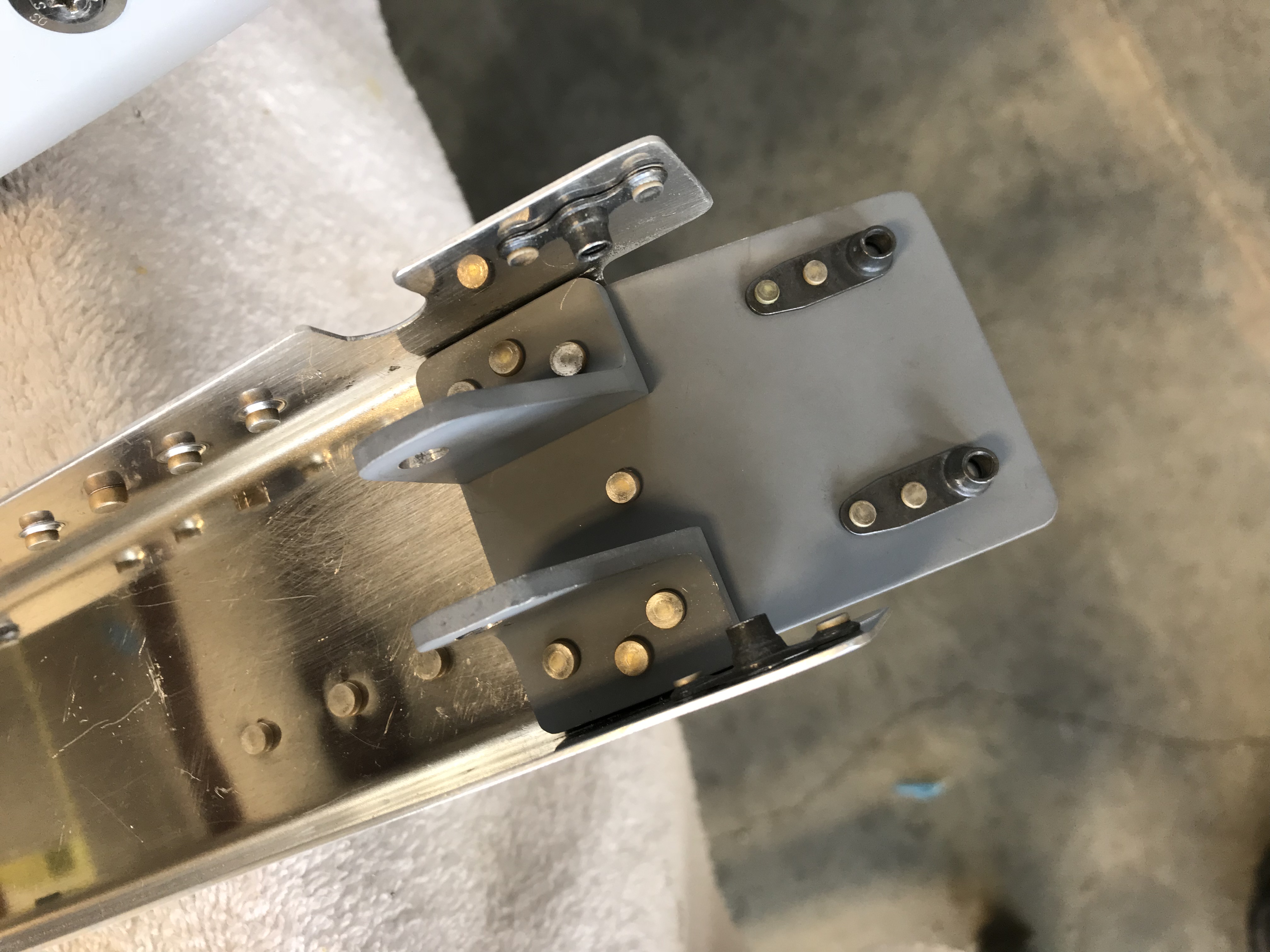
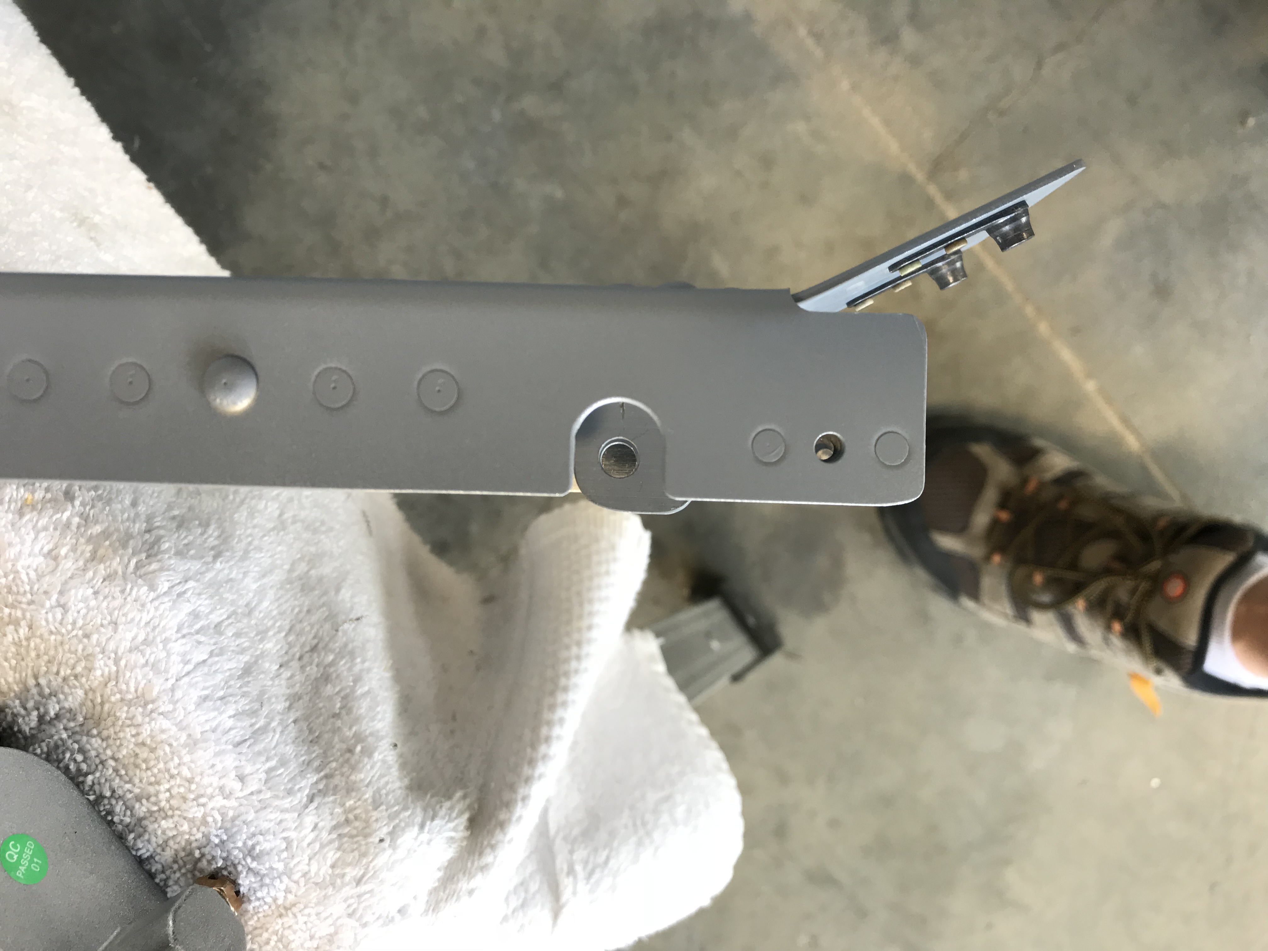
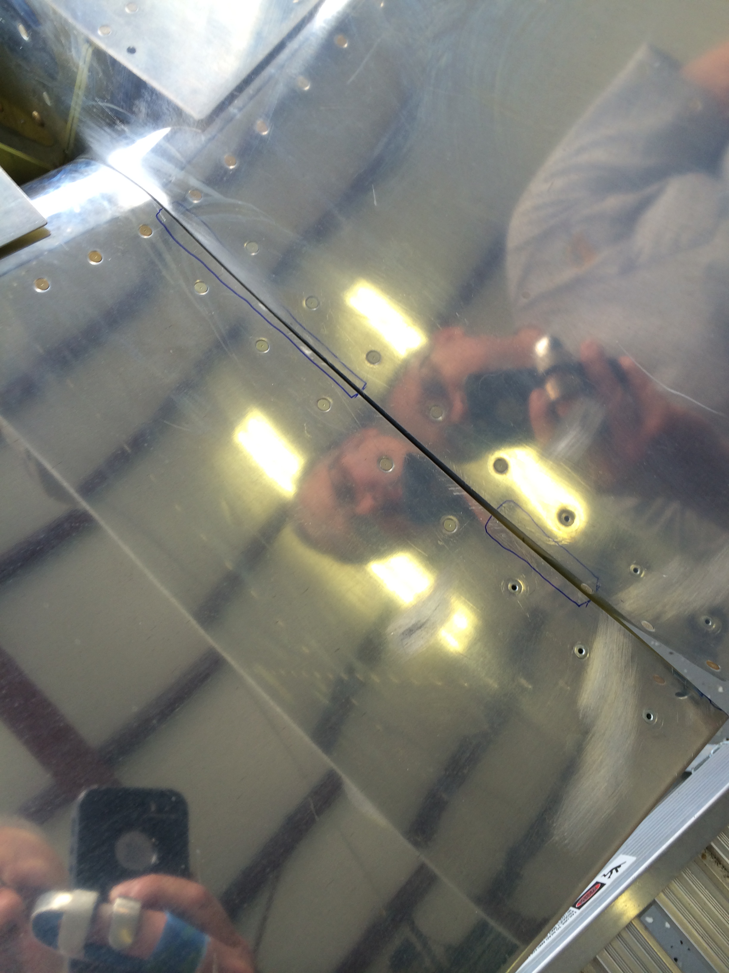
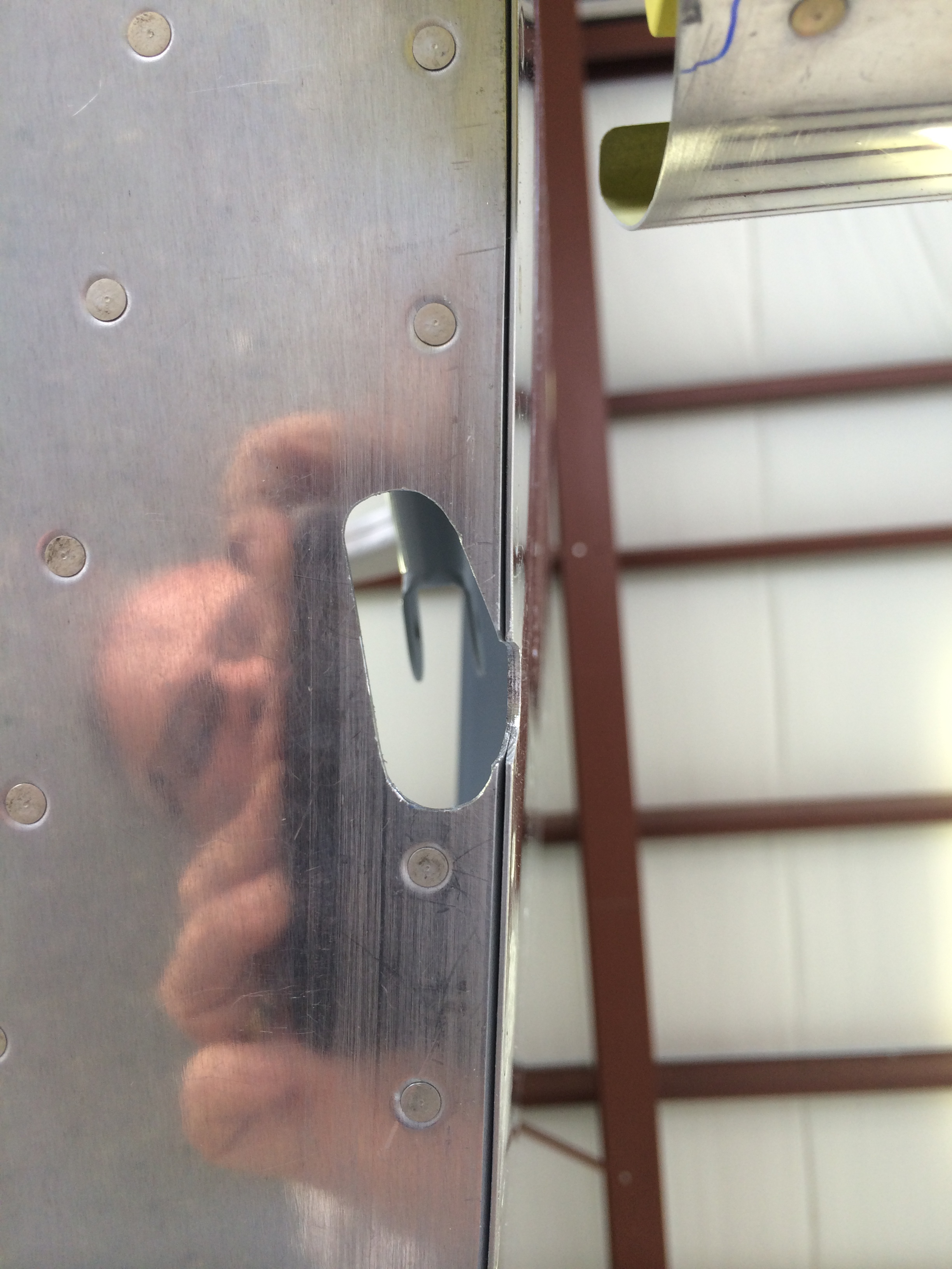
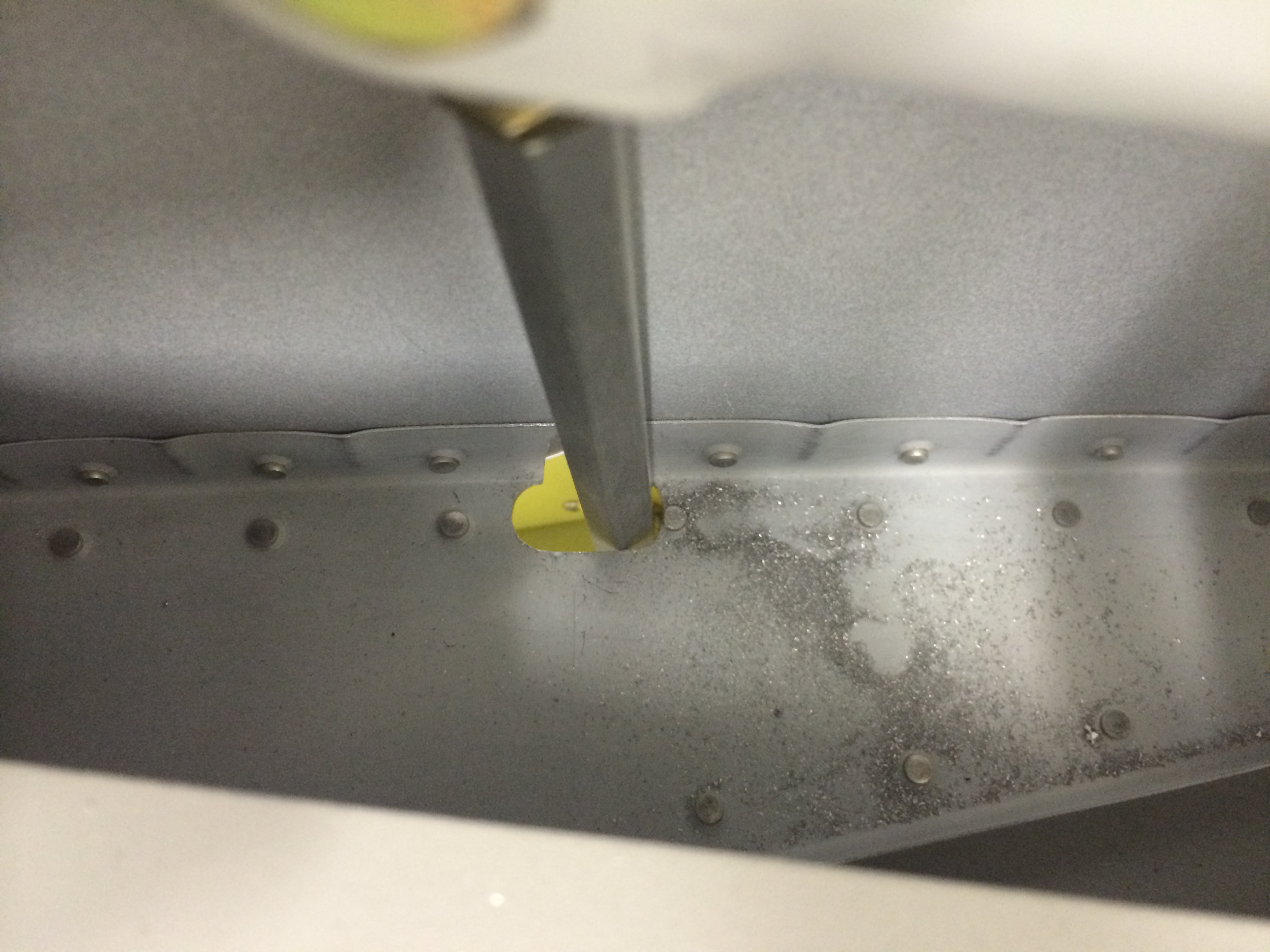
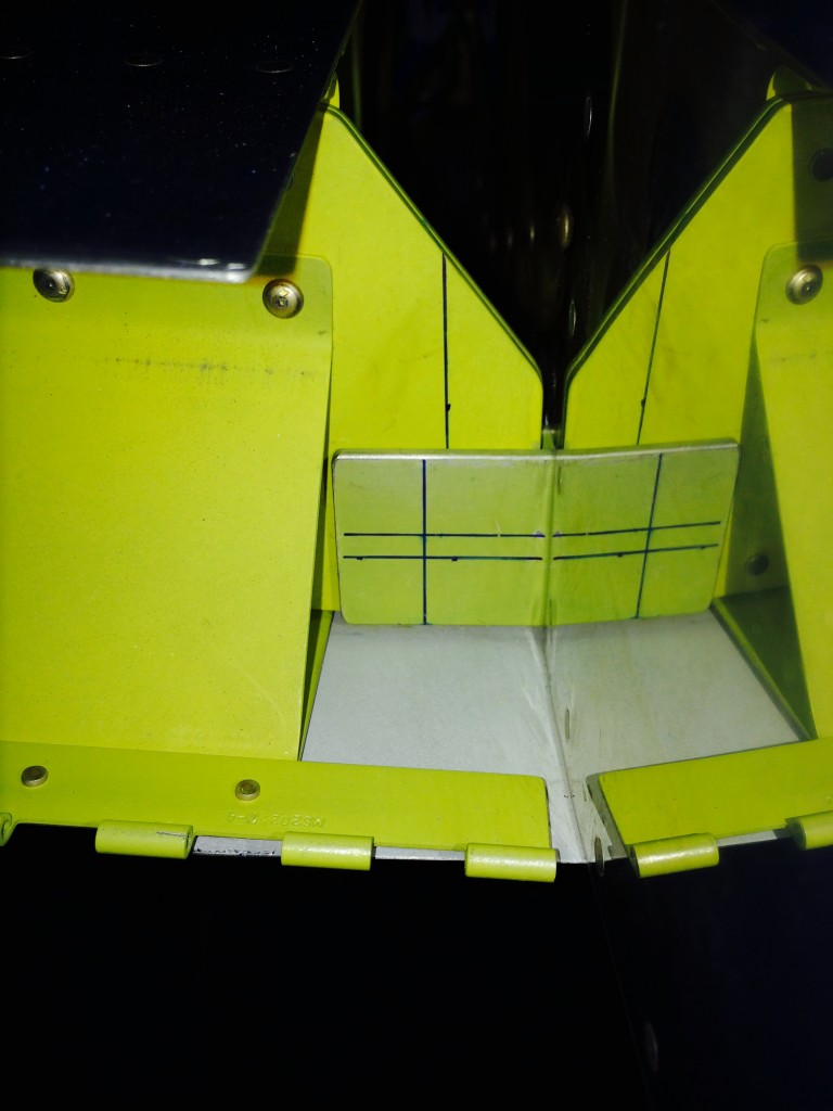
The last and most critical measurements are edge distance on the rear spar for the hole that accommodates a single attach bolt. I laid out lines on the fuselage and wing spar attachments that represent minimum edge distance from the hole center. As long as there’s distance between the vertical line on the wing spar fitting and the vertical line on the fuselage fitting, there’s sufficient edge distance for a 5/16″ bolt hole.
The right wing looks good…
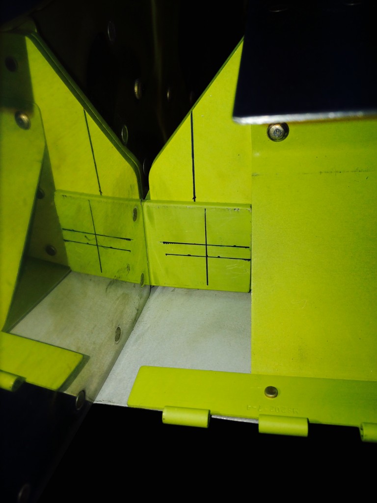
…and so does the left wing.
I’m not in a rush to drill these holes. They’re one of the few gotta-do-it-right-the-first-time things on the project, and I plan to sneak up on them one step at a time.
More to follow…

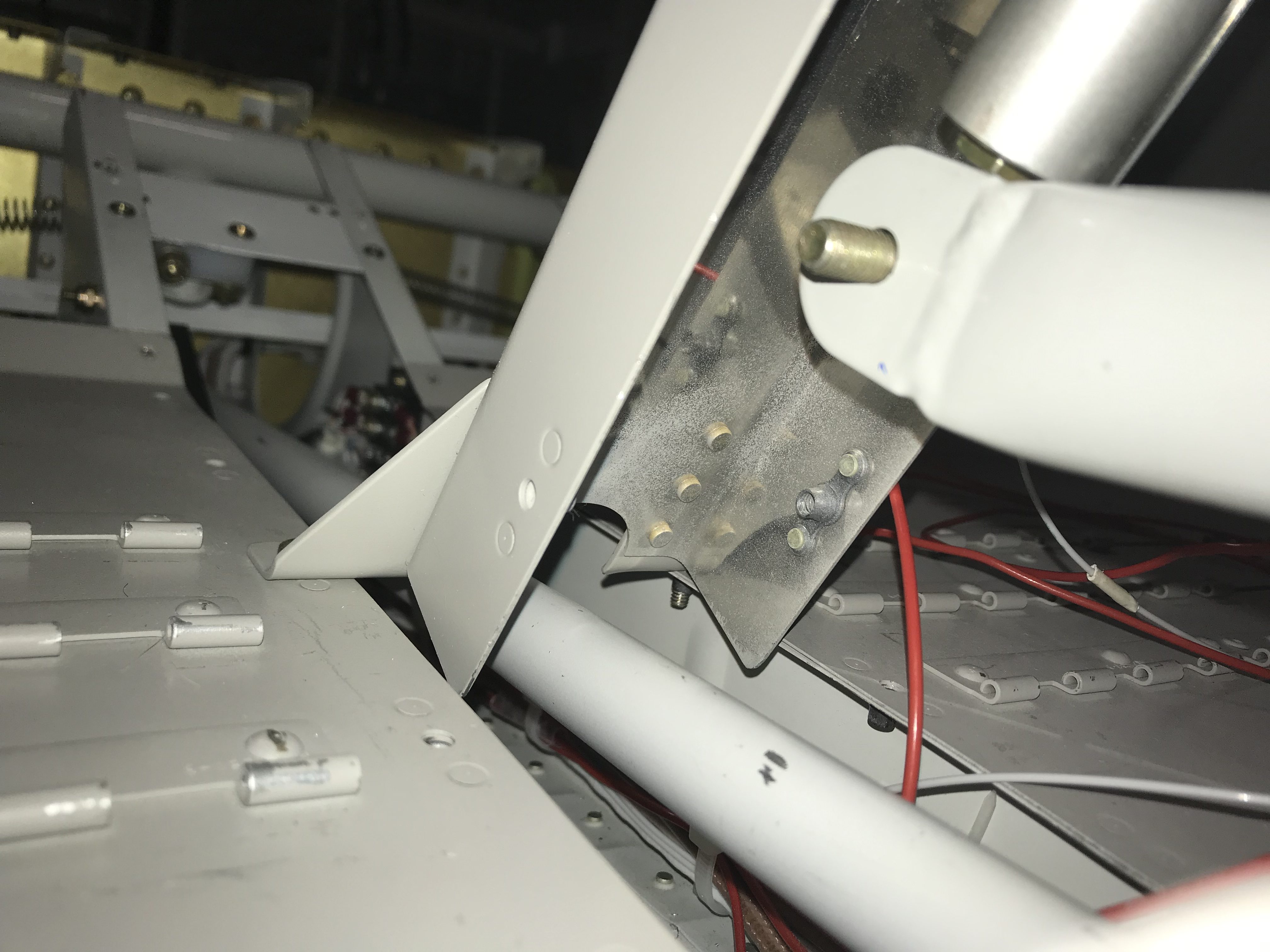
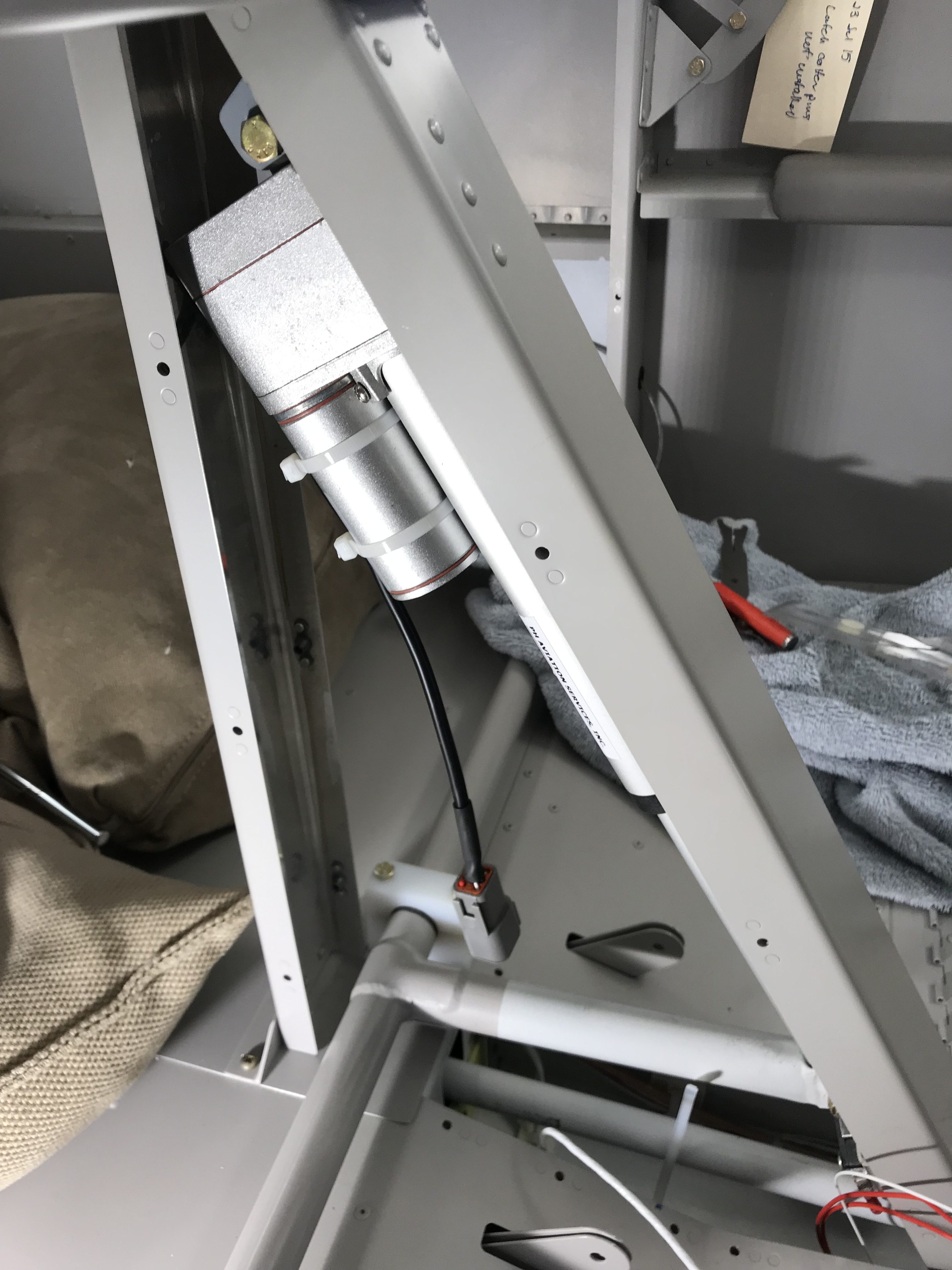
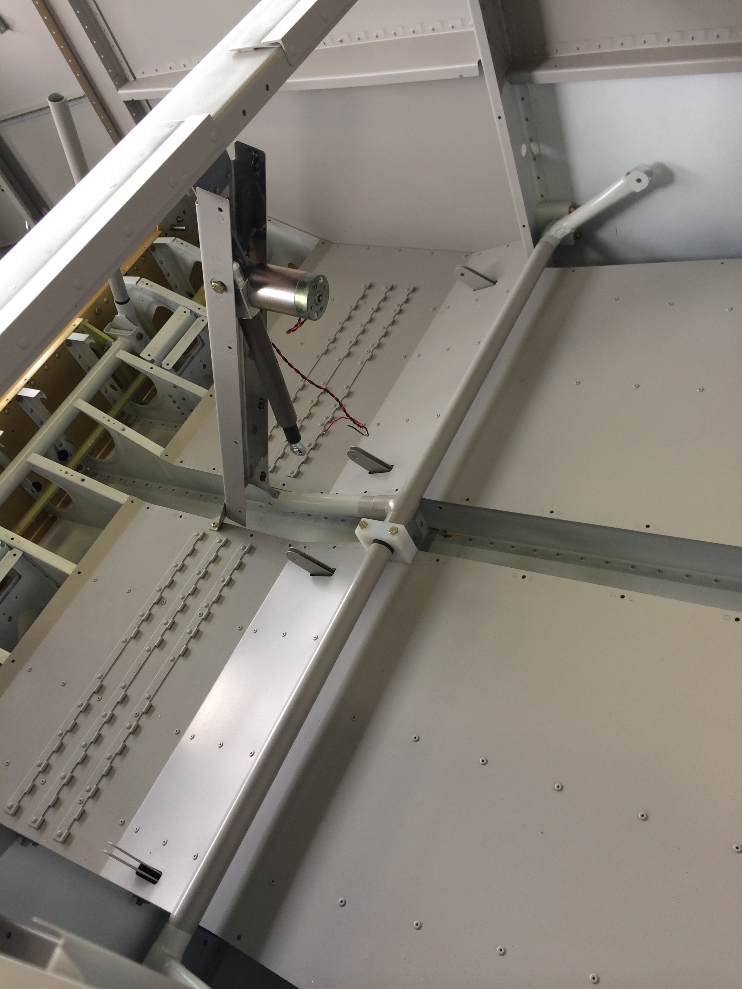
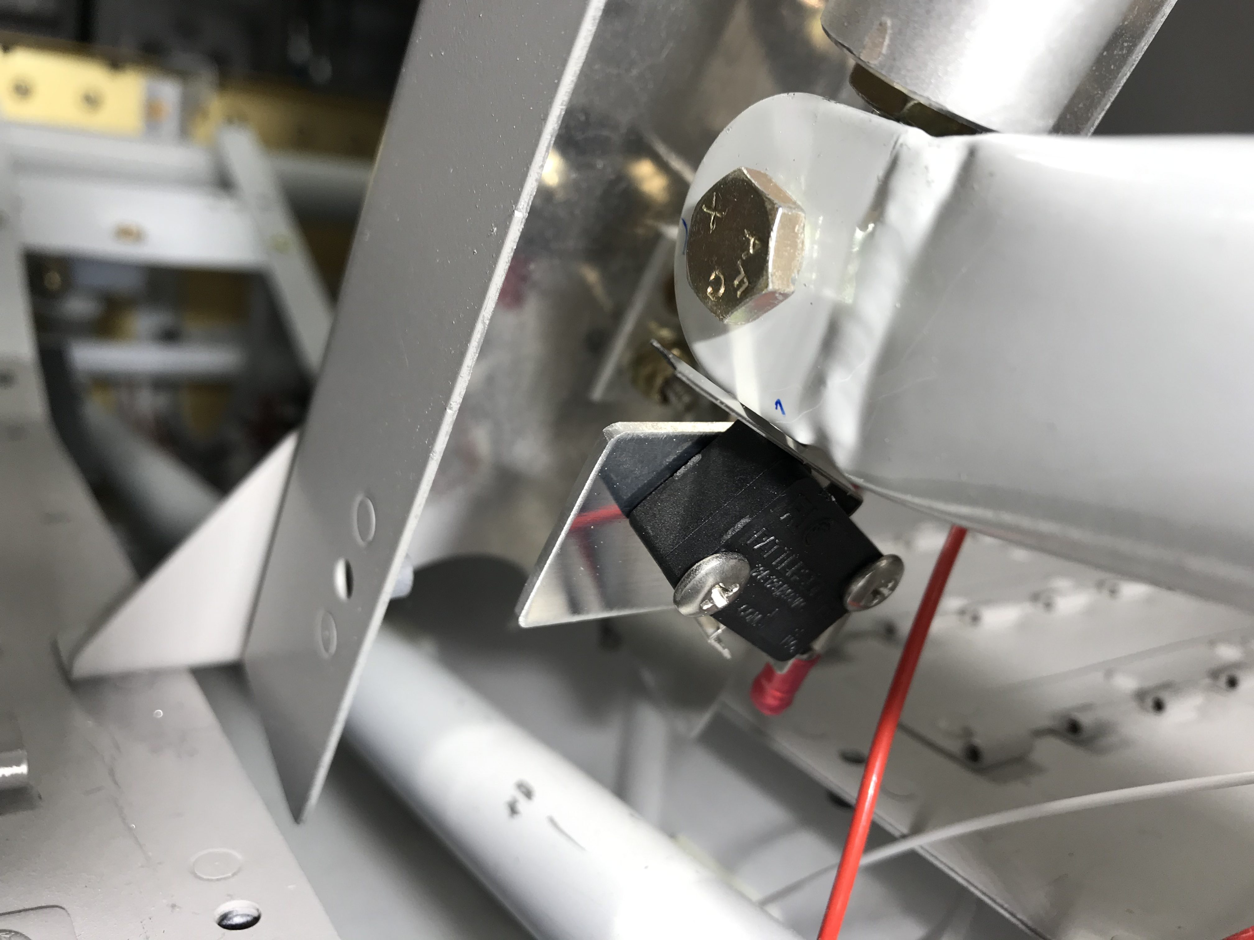 Going back to the drawing board, I put a 90-degree bend in the bracket and rotated the switch so that it’s activated by the flap arm clevis. Works great, and there’s enough play in the switch that I can adjust it later if necessary.