Every homebuilder dreams of arriving at Oshkosh for the first time in their newly-built airplane. July 21, 2022 was our day to arrive at Airventure.
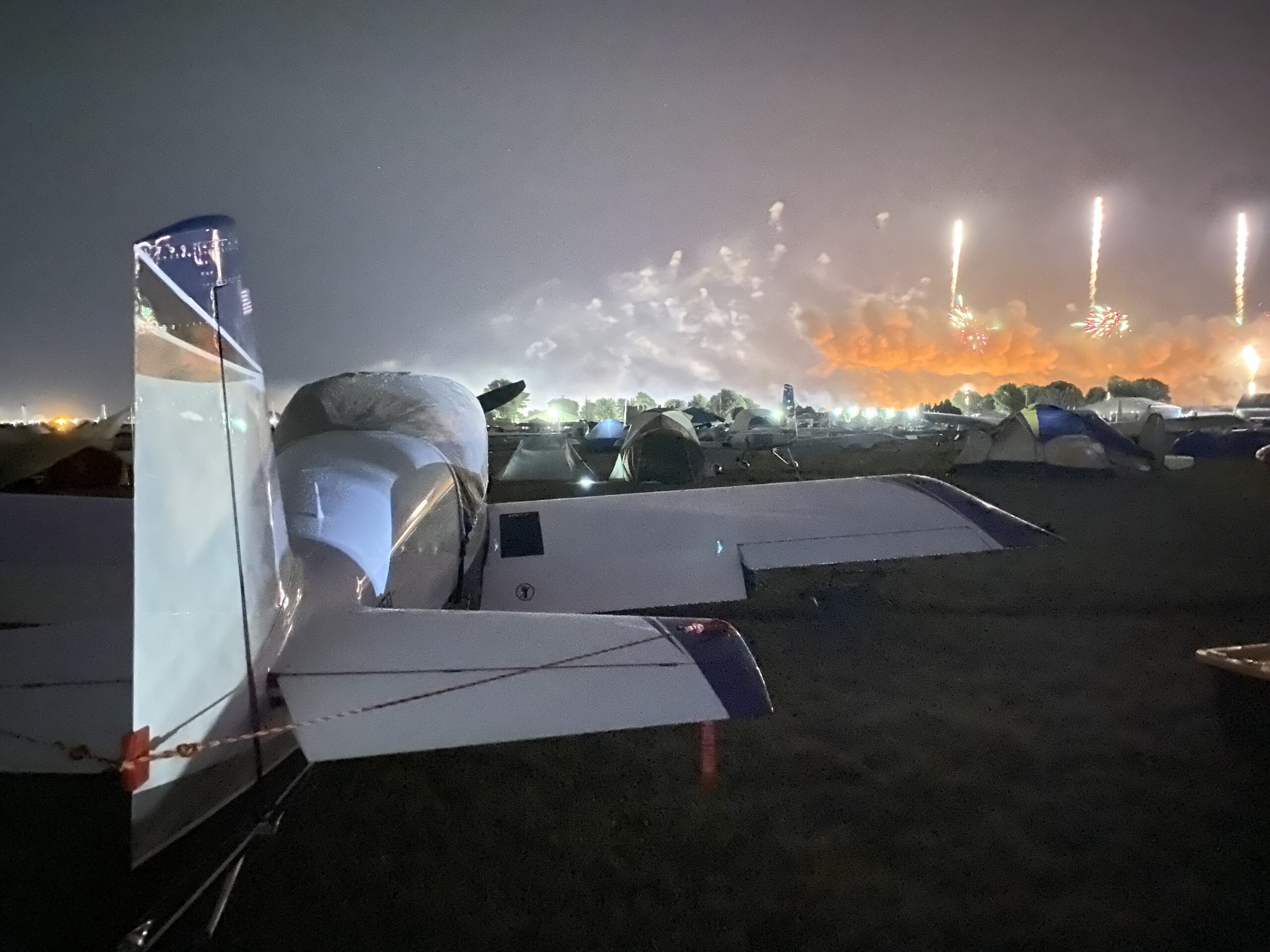
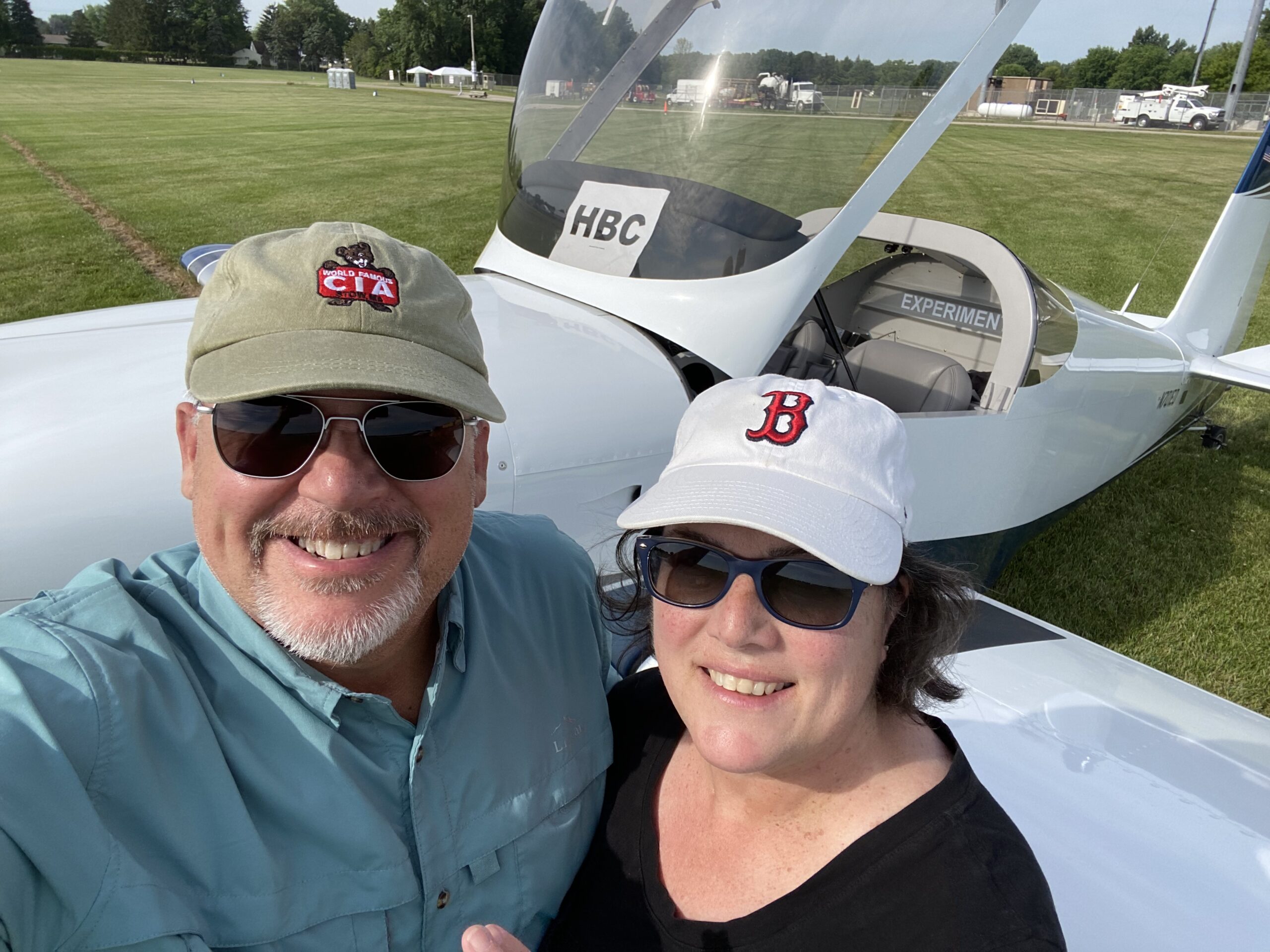 RVs and fireworks. Because why not?

Every homebuilder dreams of arriving at Oshkosh for the first time in their newly-built airplane. July 21, 2022 was our day to arrive at Airventure.
RVs and fireworks. Because why not?
More text to follow.
Some of you may have noticed that my last post is dated May 26, 2020.
 You’re about to find out. Stay tuned for more.
…I don’t want to talk about it.
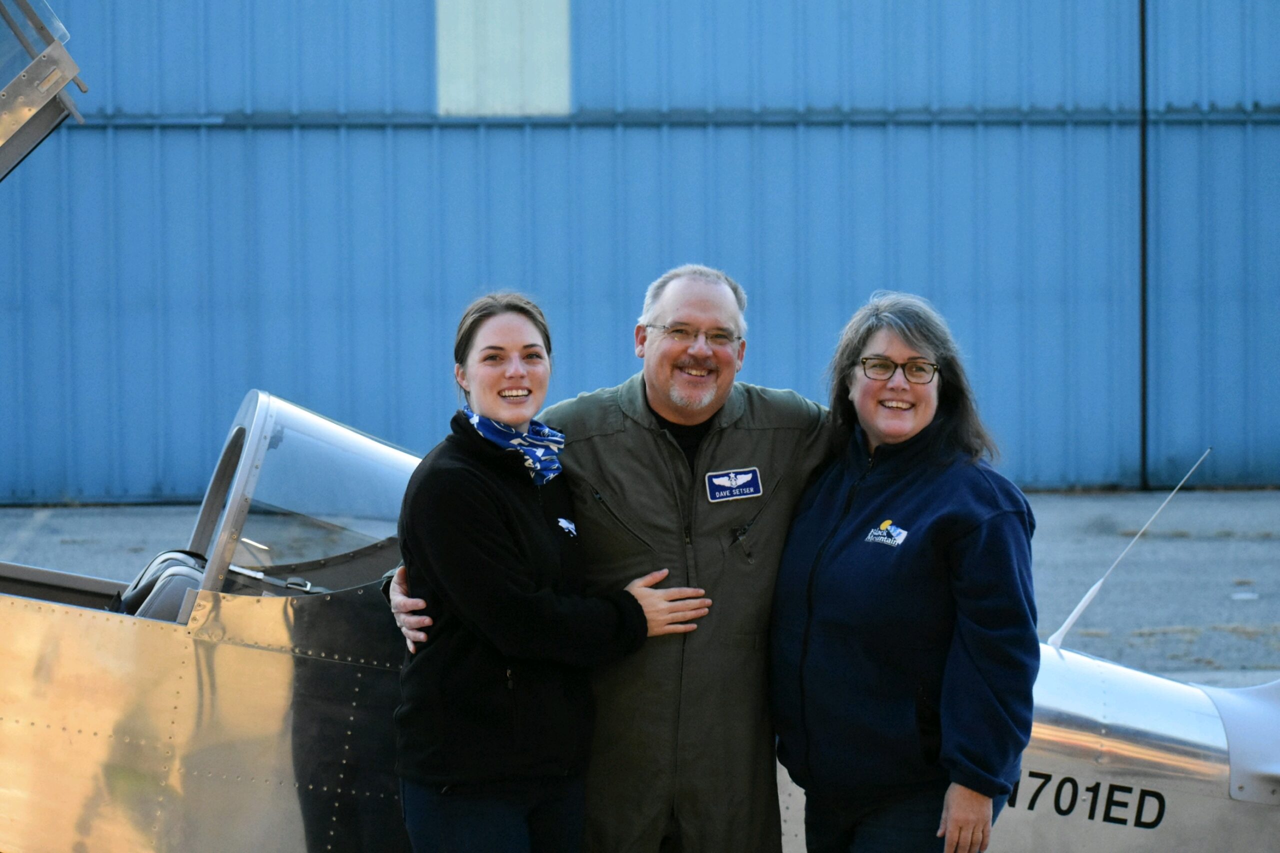
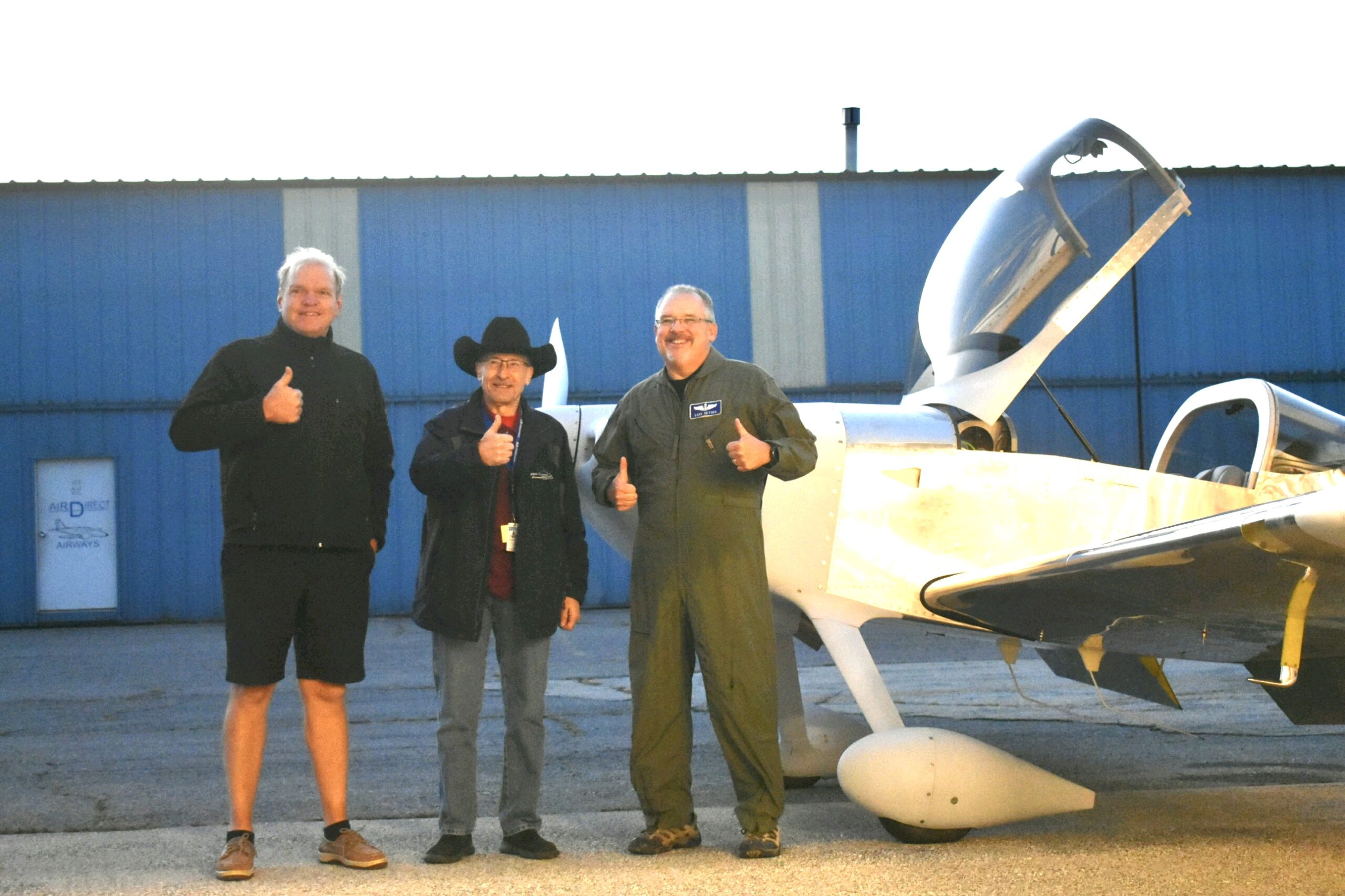
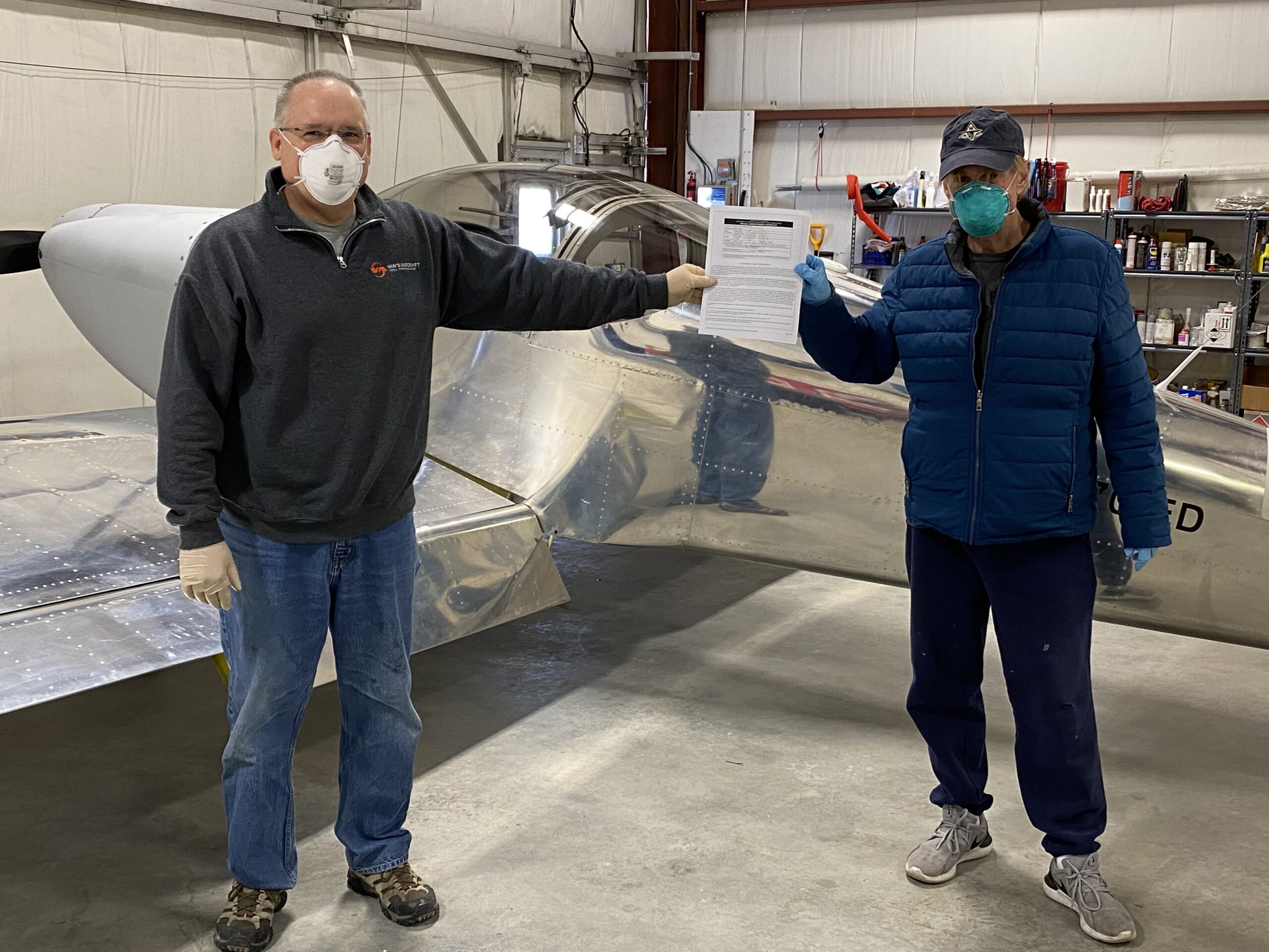
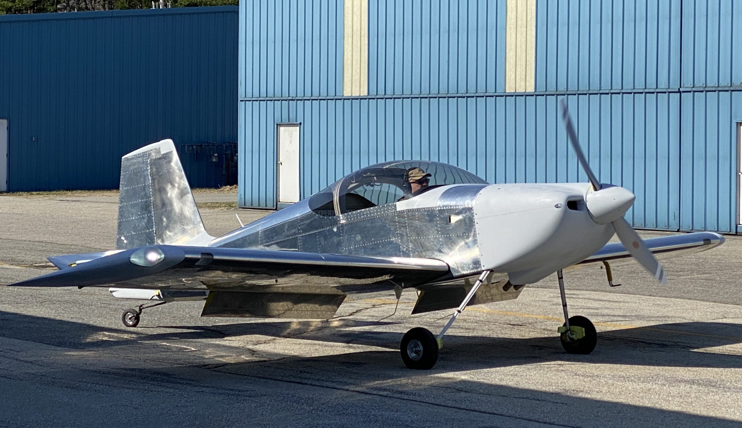
Finally…after fifteen years, the Mighty RV is officially an airworthy airplane!
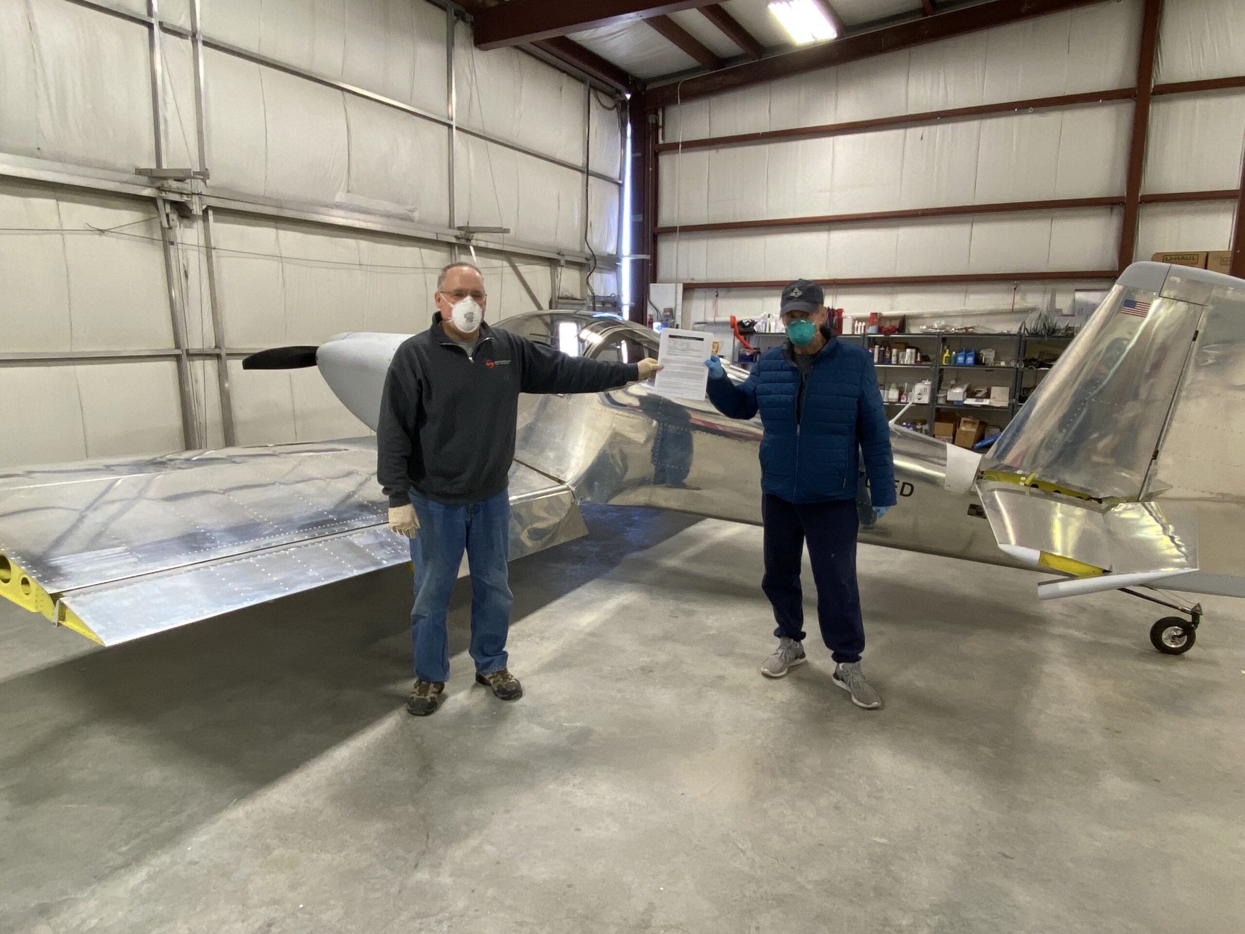 Big thanks to DAR and RV mentor Jon Ross for flying up from Long Island to do the inspection. Rest assured, we applied rigorous social distancing protocols!
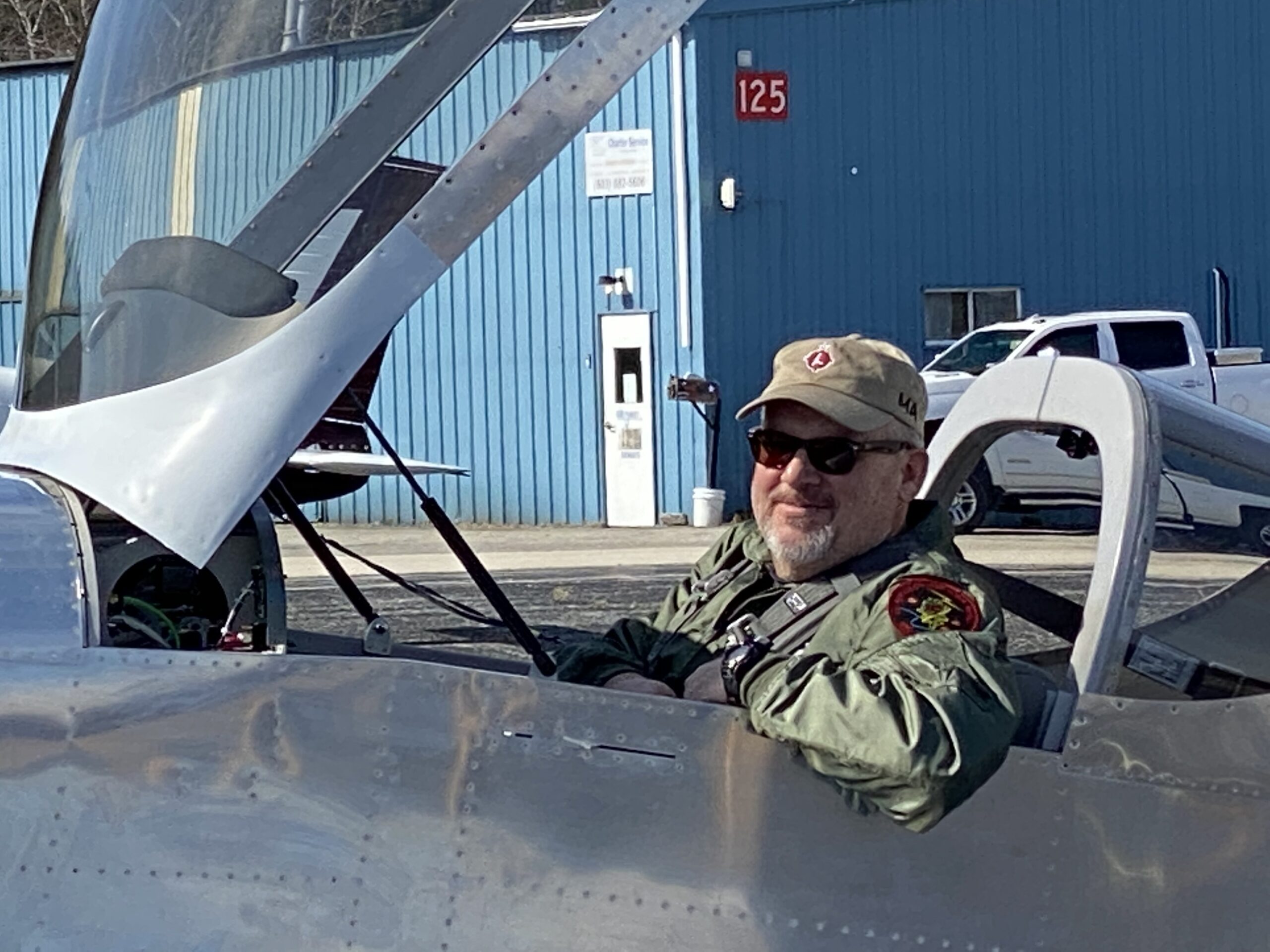
Here’s a closeup picture to prove that it’s really me…
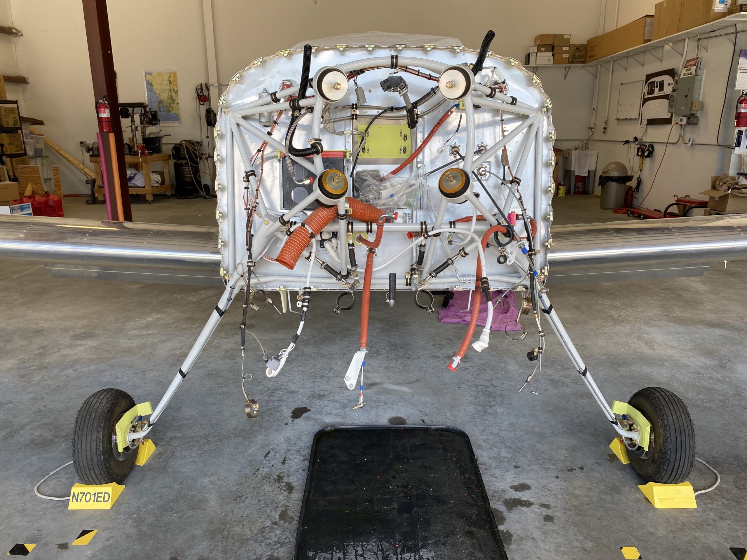
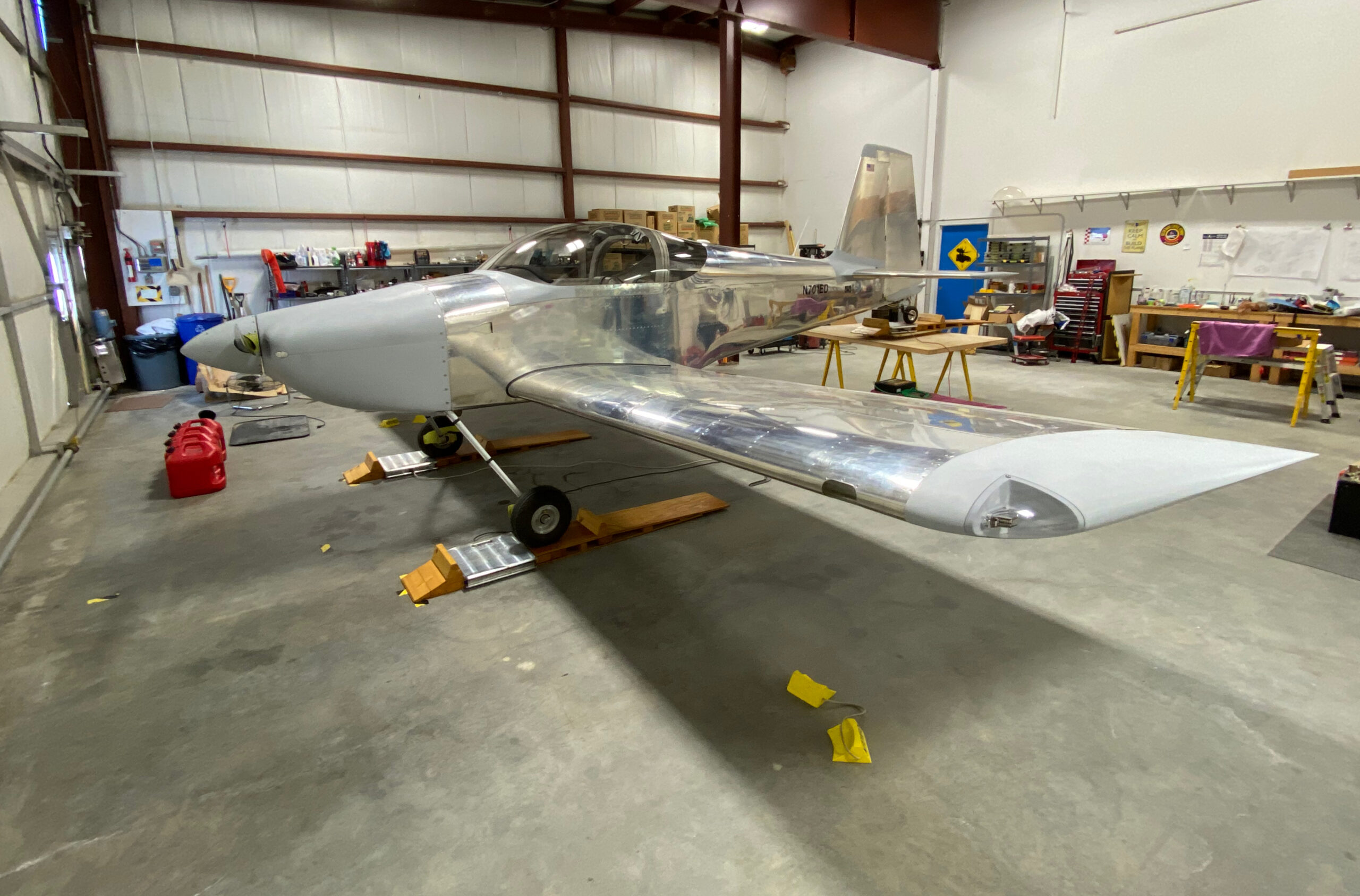
One of the last significant tasks before inspection is weighing the airplane to determine its Basic Empty Weight (BEW) and Center of Gravity (CG). An accurate BEW and CG are critical to keeping the airplane within its weight and CG limits. Fortunately, EAA Chapter 106 has a great set of ramps and digital scales that are available to members for airplane weighing…very cool!
I prepped the airplane by emptying the fuel tanks and topping oil up to 8 quarts, then set up the ramps and scales.
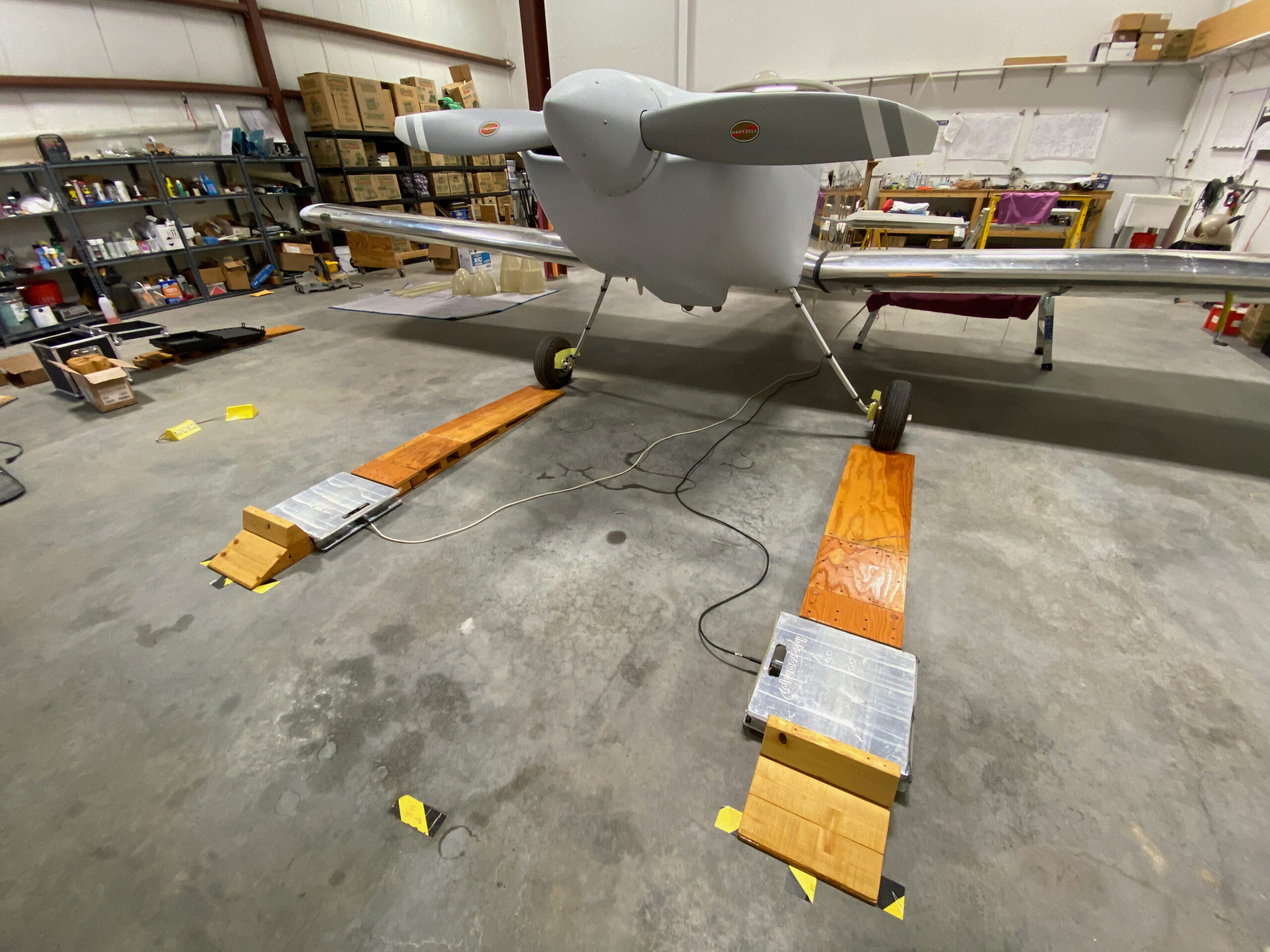
The airplane must be in level flight attitude, so Ellen and I rolled the airplane onto the ramps and leveled it by adjusting tire pressure in the main wheels and adding shims under the tailwheel scale.
The weighing process was simple. Roll the airplane on the scales, roll it off, record weight and repeat to confirm the numbers. Easy-peasy!
While the airplane was level we also measured main wheel and tailwheel distances from the wing leading edge, which is 70 inches behind the W&B datum defined by Van’s. With that number and our measurement, we were able to compute the arms for each wheel and so compute the empty center of gravity.
The results –
All in all, I’m pretty happy with the result. I had hoped for basic empty weight to be closer to 1100 lbs, but we made conscious decisions to add things like a constant-speed propeller, nicer seats and carpet that add weight but improve the airplane for travel.
Next step…DAR inspection!
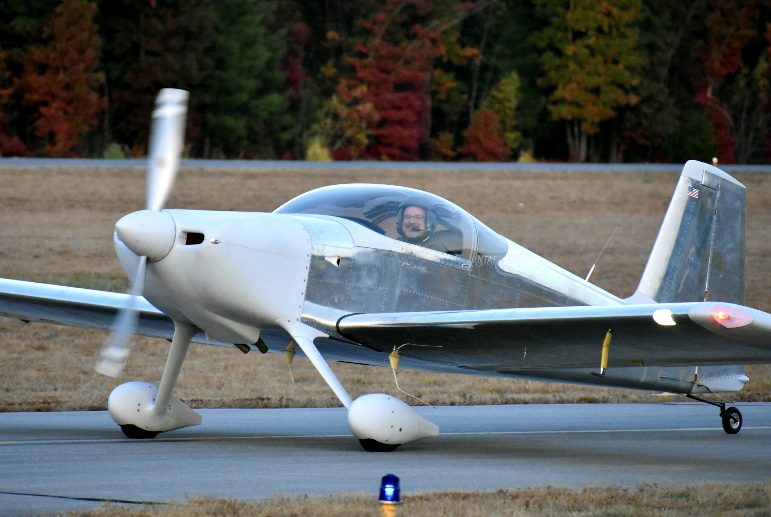
I’m following the EAA Flight Test Manual and Test Cards and the last test required before first flight is taxi and brake burn-in. Landing gear and tailwheel setup on the RV-7 are straightforward so I didn’t anticipate any steering problems on the ground, but like any aircraft test it’s the things you don’t expect that can really bite you. And since brake burn-in requires 25-30 knots groundspeed, I planned to verify steering in a large, open ramp area before heading out to the runway for higher-speed stuff.
 Fortunately, the RV-7 is very well-mannered on the ground and I had no problems with brakes or steering as I taxied to the ramp. A quick check on Comm 1 and 2 was also successful, and engine EGTs/CHTs were stable and within expected ranges.
Here’s a nice video courtesy of Ellen…
The only problem I encountered was minor landing gear shimmy – if you look closely in the video below, you’ll see the main gear tires oscillating just a bit. This is common to RVs and most builders correct it by adjusting tire pressure, adding wood stiffeners to the gear legs, or both.
Big props to Ellen…she was my ground crew and called on the radio to ask if I felt vibration, which I did, but wasn’t sure what it was.
After finishing taxi tests and brake burn-in, I finished the G3x full-power vibration survey and magnetometer calibration. It’s good to have the avionics completely done!
 Thanks to Burt Wadas for being my official ground-test photographer!
The last major task on my to-do list was balancing the elevators. Van’s instructions aren’t super clear on whether to do this before paint, but a call to Sterling at Van’s confirmed that the elevators must be balanced before first flight. Works for me.
I decided to put together a simple rig for balancing – two pieces of aluminum box extrusion trimmed and drilled at one end to accommodate elevator hinge bearings and bolts to hold them in place, both clamped to an aluminum work support. Here’s a pic –
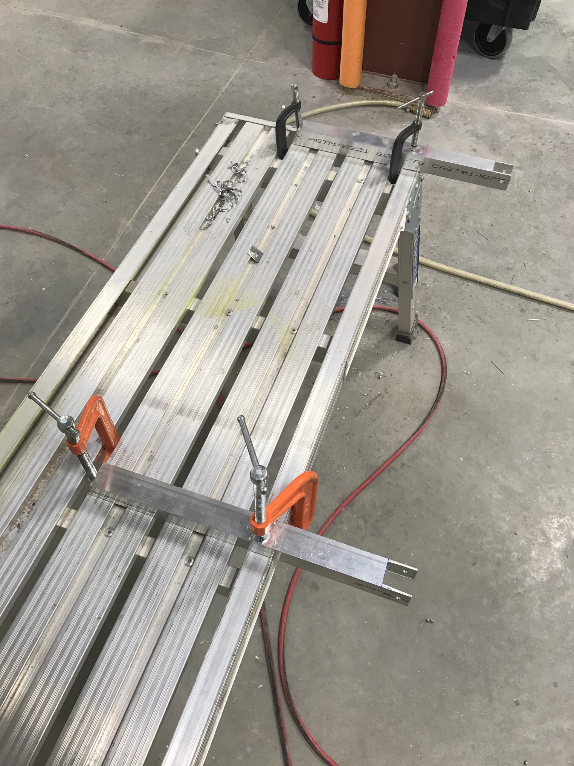
The left elevator needed some weight and I had to remove some from the right elevator.
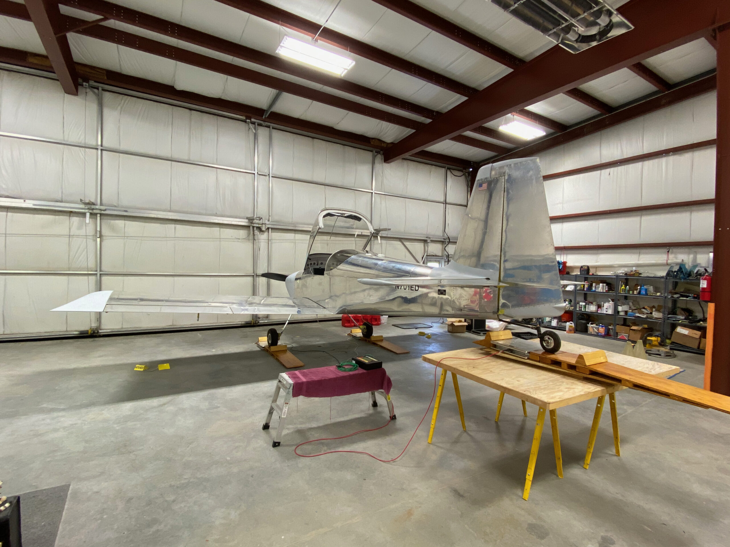
With balancing complete the elevators went back on the airplane and the airframe exterior is DONE!
Another finish-up task is done – installing LED nav/strobe lights on the wingtips. It was an easy job, simply installing the light mounts and connecting the lights themselves to wiring runs from the wing conduits.
 All lights in action…the Mighty RV is ready for the night show at Airventure.
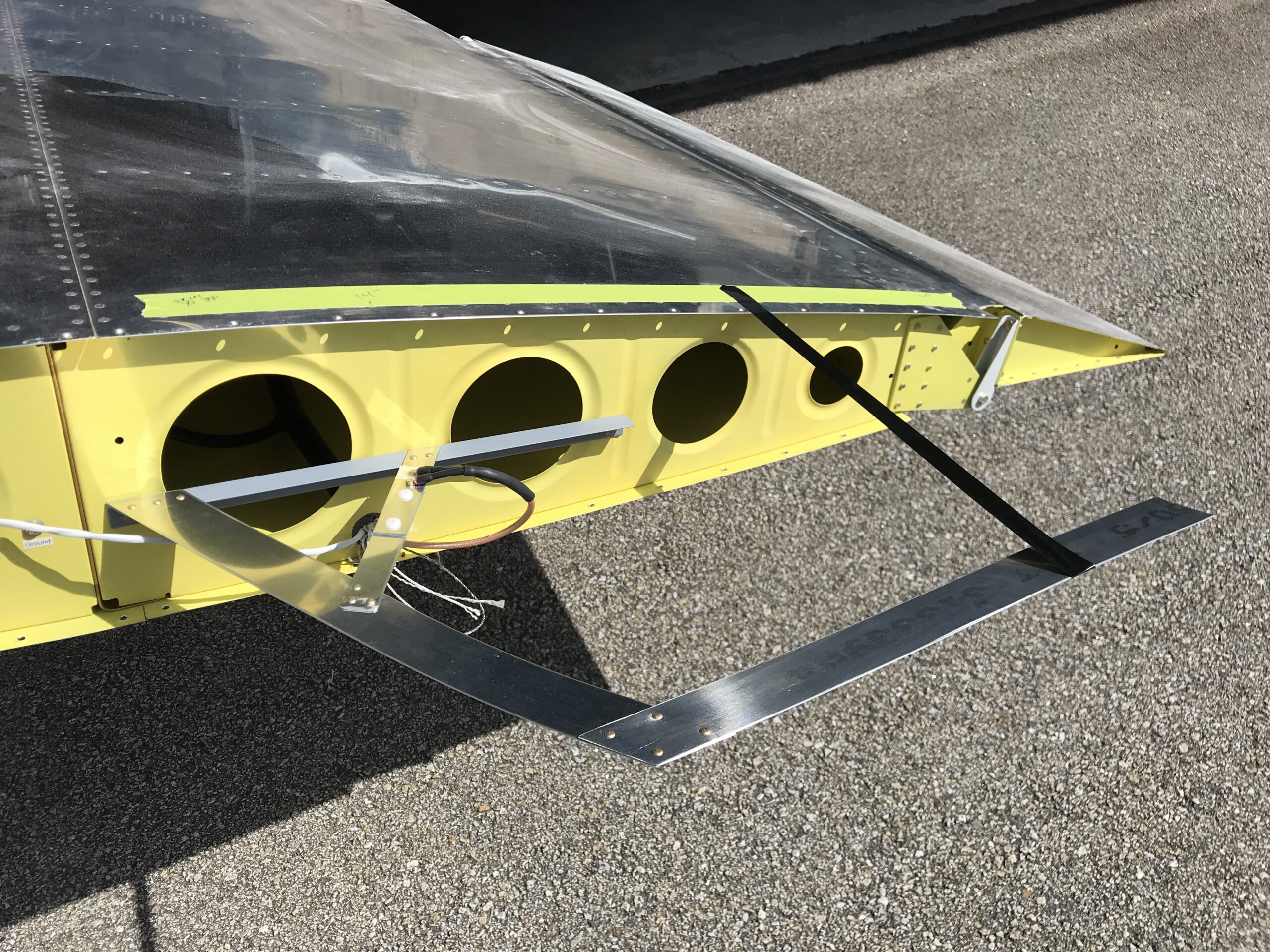
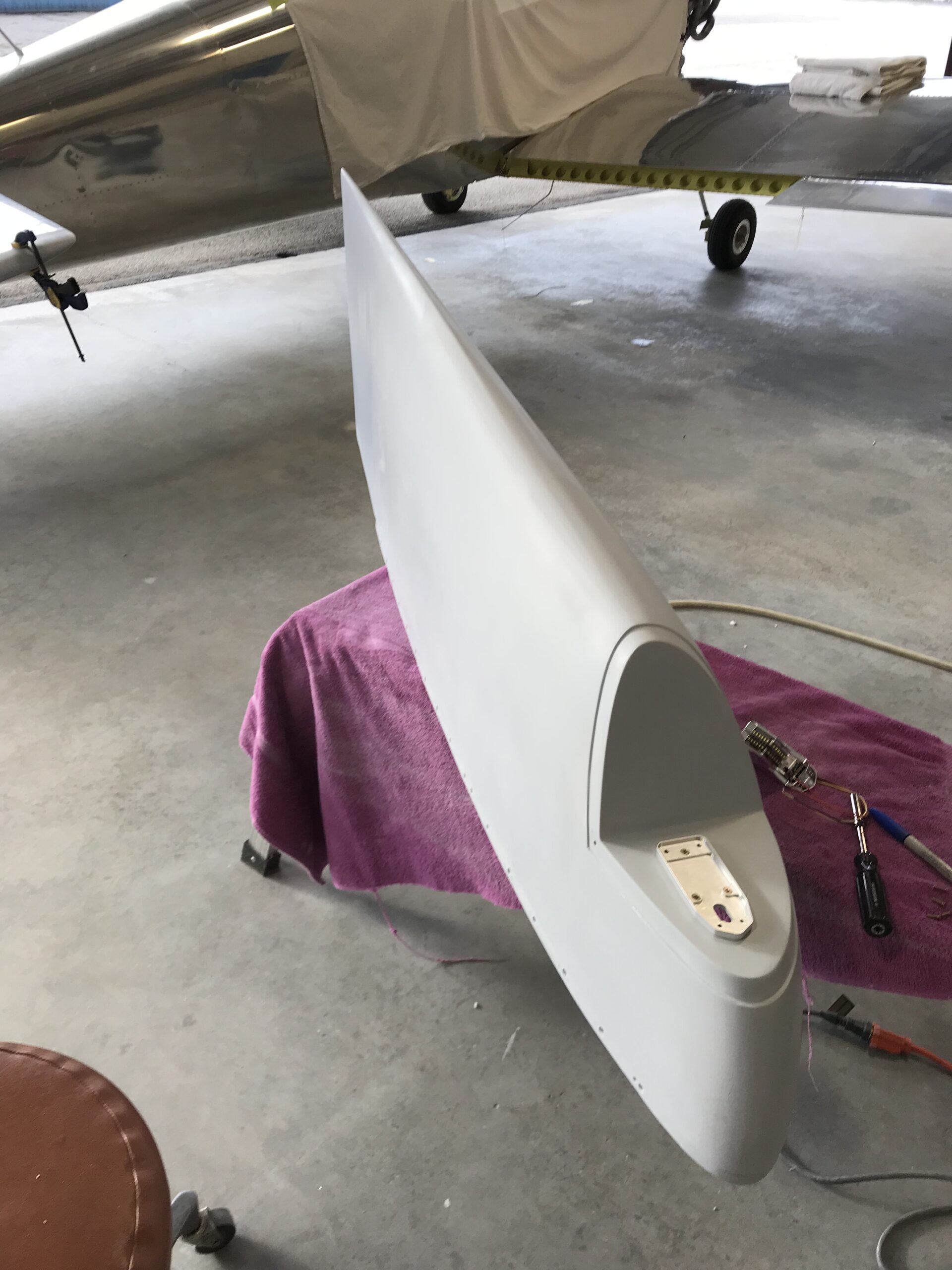
…Nav antenna, that is. I had always planned on using a Bob Archer-designed wingtip Nav antenna because they work well for horizontally-polarized ILS/LOC/GS signals and also fit nicely within the wingtip fairings, thus eliminating a tiny bit of parasitic drag. You can find Bob Archer’s description of his antennas here and instruction/plans for building them here on Van’s Air Force.
I was all set to buy one of Bob’s antennas from Aircraft Spruce. But since I’m an Electrical Engineer by education (can’t spell “geek” without EE) as well as an airplane homebuilder and ham radio operator (N1DLS), I decided to make my own antenna out of some materials I had laying around the shop and a piece of fiber/resin circuit board material I bought from McMaster Carr.
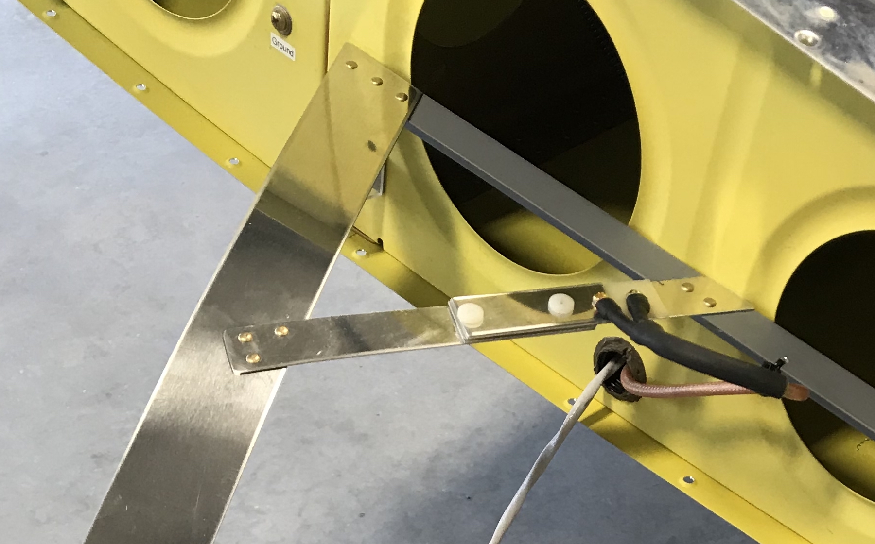
There’s nothing difficult about fabricating the antenna, it’s only an afternoon’s work to put one together using plans you’ll find on the interwebs.
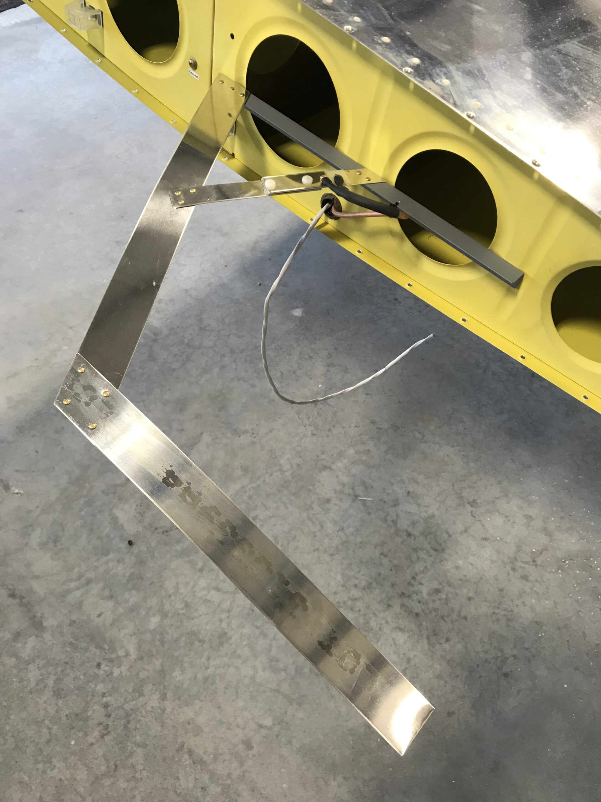
The magic in this antenna lies in a couple of areas – the gamma-match coax impedance-matching device, which is the narrow aluminum and fiberglass structure to which the coax connects, and the length of the long outboard aluminum strip that’s parallel to the wing. The antenna must also be well-grounded to the aircraft, hence the big piece of aluminum angle that holds it onto the wing.
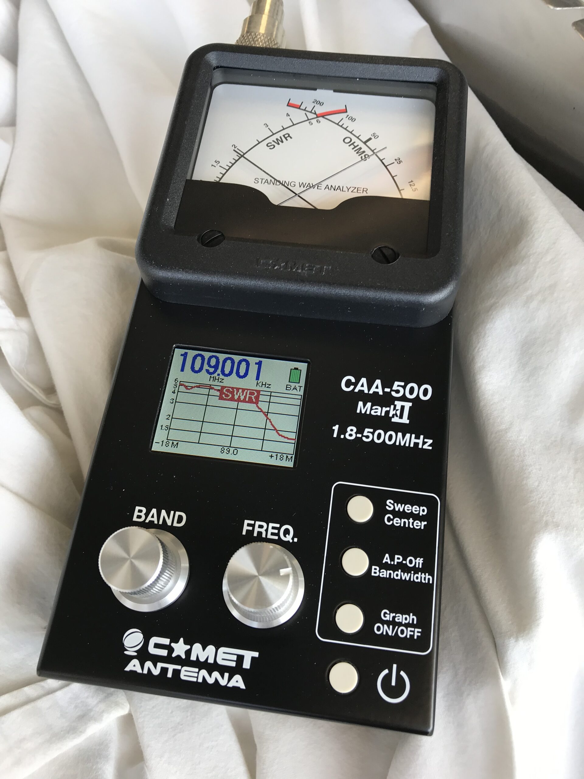
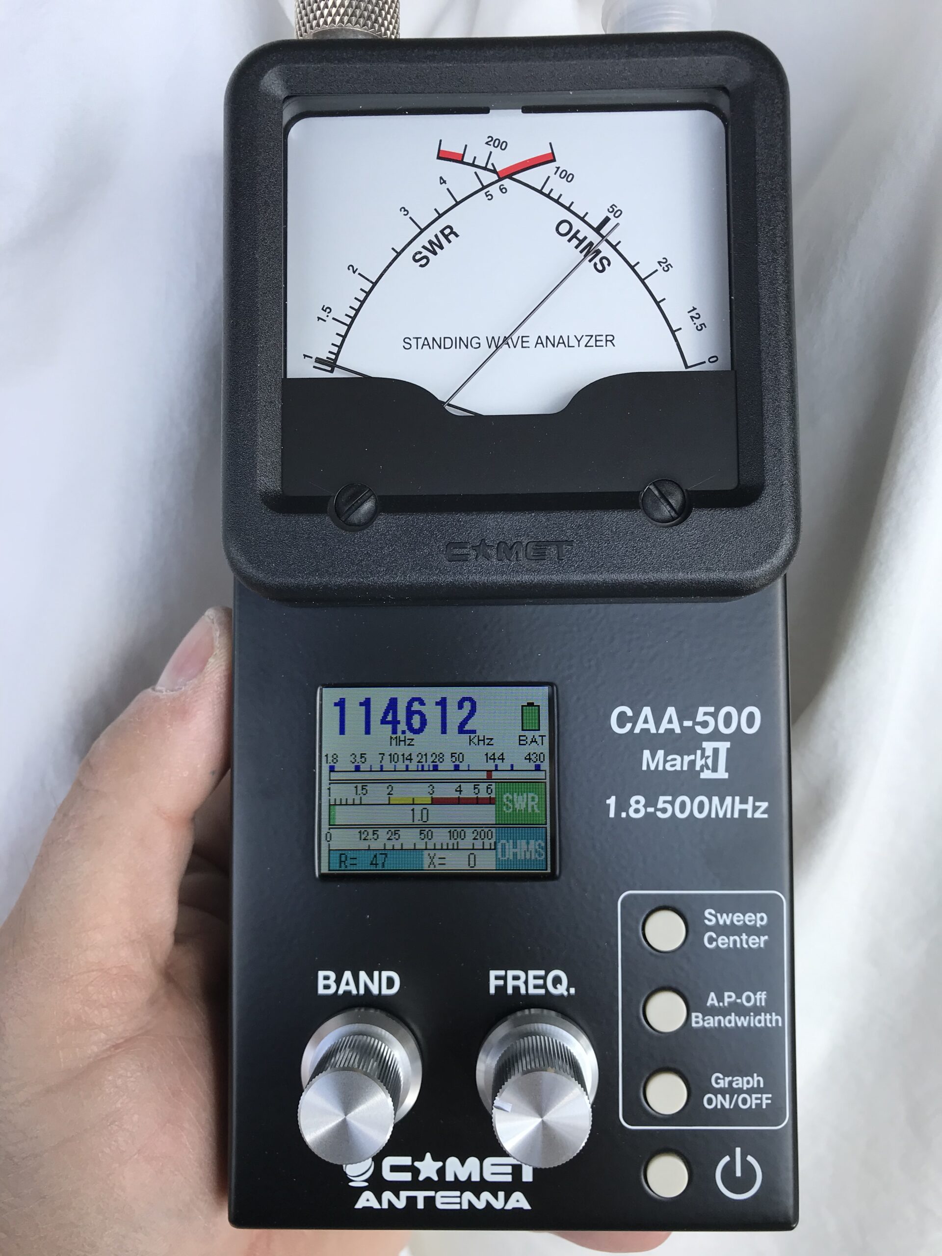
So how does the novice Archer antenna builder know how to adjust these magic bits? The answer is an antenna analyzer, something which no self-respecting ham radio nerd would be without. Here’s mine –
The instructions should tell you how to tune the antenna but if you need help and an antenna analyzer as well, hit up your nearest airplane-building ham radio buddy (there are a lot of us) and he/she/I will be glad to help.
After several iterations of adjusting the gamma match and antenna length, I had a well-tuned and matched antenna…I hope. The analyzer picture below shows that the antenna is almost perfectly matched at 114 MHz. I can live with that.
And here’s the final product –