Applying pressure

I started back to work this week for The Man…a different Man, and this one pays better!

It’s been awhile since the engine has been turned over and since the first start is approaching, it’s time to pre-oil the engine. Superior’s manual says that you can do that by either applying oil at 35 PSI into one of the lubrication galley ports on the front of the engine, or by cranking it with the starter until the oil pressure sensor shows 20 PSI. I chose to do the latter as it’s less mess and is also a good test of the G3x. I loosened slightly the oil pressure line AN fitting at the sensor end so air could escape. Made a little mess when the pressure came up, but was easily cleaned.

A video is worth a thousand words and there’s not much else to say anyway.

Big thanks for Mike Henning and Bob DiMeo for their help!

Wiring and plumbing the wings

We’re getting close to Oshkosh and I wanted to get as much done as I could before our trip, so over the weekend I installed the pitot tube and wired landing lights, OAT probe and pitot heat to their circuits in the fuselage.

Here are the Baja Designs Squadron Pro landing lights connected and doing their thing. Not terribly bright in this picture but they hurt to look at, and that’s a good thing…

Landing lights

No post on landing light installation would be complete without proof that the GAD-27 can indeed flash the lights…

I had fitted and plumbed the pitot tube several years ago so installation was relatively straightforward – just had to connect the AN plumbing and heater connector, then screw it to the pitot mast. And yes indeed, it gets hot…

Heatet pitot is hot!I screwed up the fuel tank feed lines, so some surgery was required to install an AN union and line to the left fuel tank. Once that was done, I reinstalled the vent line I fabricated a few years back. The RG-316 coax you see snaking out from the rubber gasket is a line that connects a Princeton capacitive fuel level sender to the fuel tank’s BNC connector.

Left fuel tank plumbed

Same thing on the right wing…

Right fuel tank plumbedPlumbed the right wing as well, and installed the fuel tank support bolts on both sides.

Pitot-static and OAT connected

Connected the OAT probe and pitot-static lines in the cockpit.

More right wing plumbing…and finished connecting the right fuel tank. Had to do another splice job on the fuel line, but it came out fine.

And now we’re off to Oshkosh!

Miscellaneous engine tasks

Lots of little wrap-up tasks remain…this weekend I installed engine sensors.

Here are the PMag connection, oil temperature, current shunt, manifold/fuel/oil pressure and fuel flow sensors all wired…

Engine sensors wired

CHT and EGT probes wired on cylinders 2 and 4…

Cylinders 1 and 3 sensors

…and the same on cylinders 1 and 3.

Cylnder 2 and 4 sensors

I’ve been putting off safety-wiring the prop bolts ’cause it’s a reall pain in the ass.

Prop safety-wired and spinner installed…but now it’s done, and as a treat to myself I installed the spinner!

On the wing

Now that I’m done with transition training, I’m all fired up to finish the Mighty RV. So..let’s get those wings on!

Starting the wing installThe promise of beer and burgers made it easy to co-opt some of my flying and/or RV-buidling friends to come over to the ThermosWorks on Saturday. The wings aren’t particularly heavy, but a few extra pairs of hands come in handy when trying to maneuver the wing spar into it’s slot in the fuselage.

Another wing install

Mark Masse (RV-7 builder) and Rich Snyder (RV-8 builder) work the left wingtip up, down, left and right while Mike Henning (RV-4 builder/flyer) guide the spar into the fuselage and Burt Wadas (best friend) positions tapered stainless steel pins to align bolt holes.

The last left wing install pic

Almost done…there are two close-tolerance bolts inserted now, enough to hold the wing in place til the rest of the bolts are installed.

Right wing install

Onto the right wing…same process, but much faster the time.

Another right wing install

You can’t see him in this picture, but Bob DiMeo (RV-8 builder/flyer and my Technical Counselor) is waiting to insert tapered pins in while Burt and I position the wing spar.

Sucking it in...

Fast forward an hour or so…the wings are in place and all bolts inserted. Everyone who has a gut is sucking it in for this picture!

B-e-a-youtefull!

After burgers and beer, Ellen and I pushed the Mighty RV out into the sun for some pictures. Beautiful, ain’t it?

Even more beautiful

Another picture, I knew you’d ask for it.

Finally beayouteefulAnd finally, a really nice shot captured by Ellen. This is a big day in the life of the project – we’re a huge step closer to flying!

Transition training time

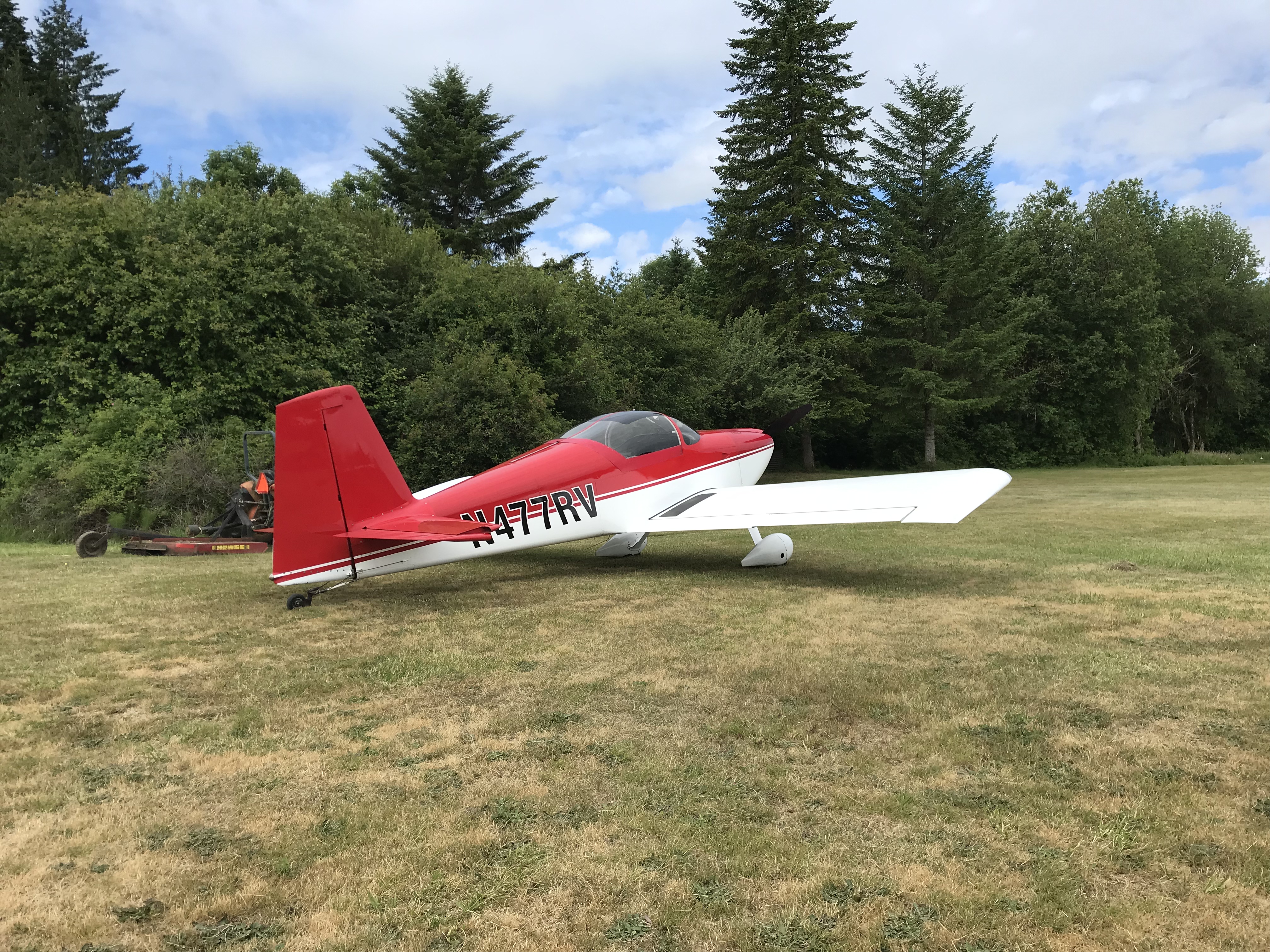
I’m not good at forecasting completion dates for the Mighty RV, but I took a chance on being done this Summer/early Fall and booked transition training with Mike Seager this week in Vernonia, Oregon in the factory RV-7 trainer, N477RV.

N477RV

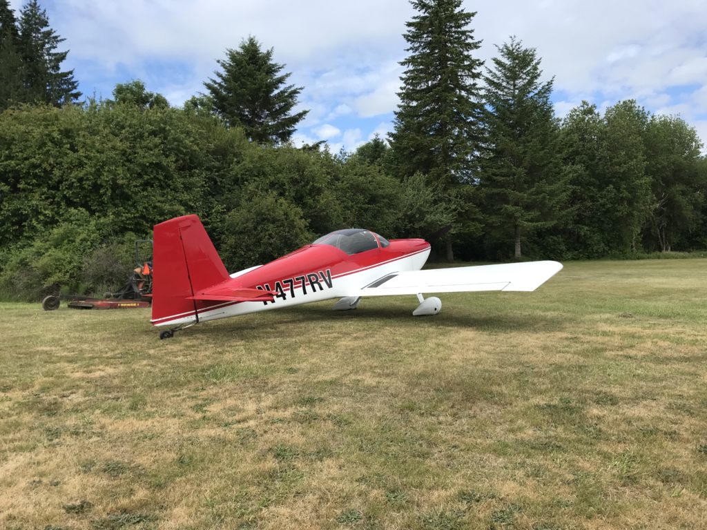
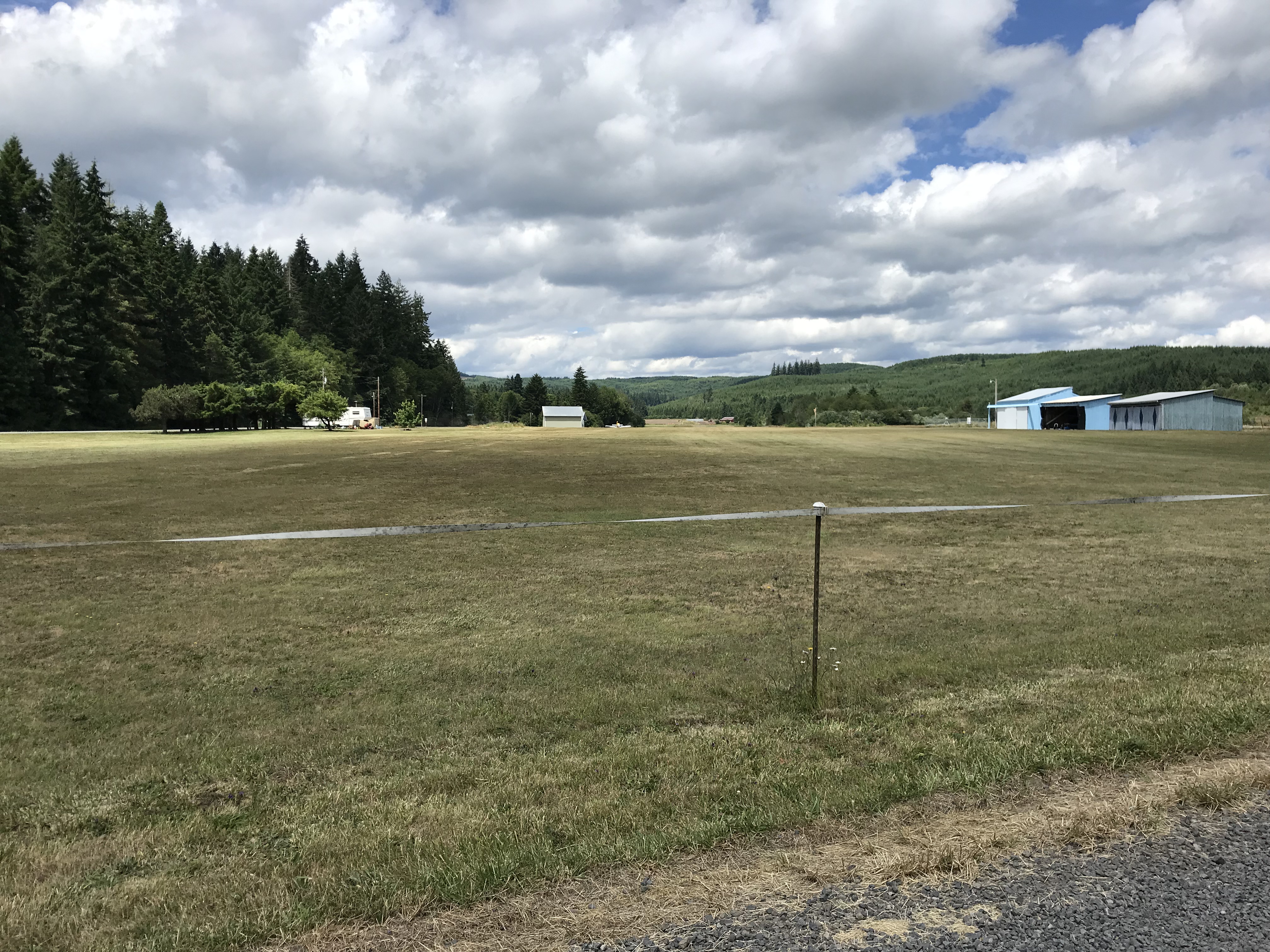
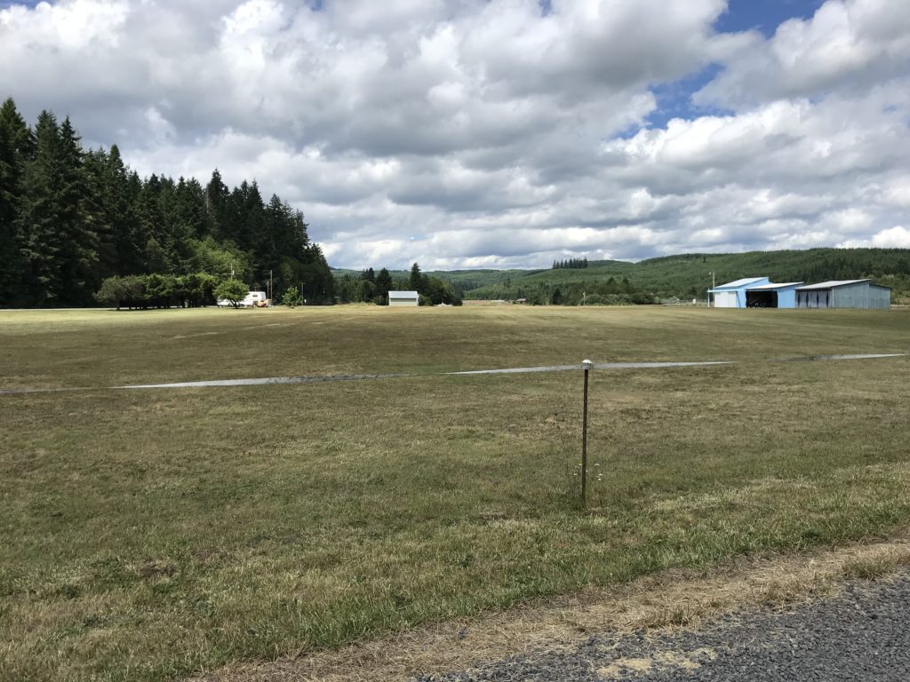
Vernonia Municipal (05S) is beautiful and quiet grass strip with only a few hangars.

Vernon OR airport

I put off my airline and lodging reservations as long as I could – probably a little too long. It’s not particularly easy to find a place to stay in Vernonia, but my wife came across a really great place on Airbnb that’s only a mile or two from the airport…

A great place to stay

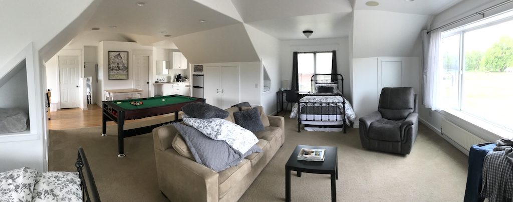
Tamara and her family are great hosts, and their guest suite is spacious, quiet and comfortable. I highly recommend you check it out if you’re traveling to Vernonia for training with Mike!

The first flight on 26 June was a short intro flight from Vernonia to Scappoose (KSPB)…

27 June first flightTurns out that my first landing in Scappoose was one of only a few really good landings I made that week!

26 June second flight

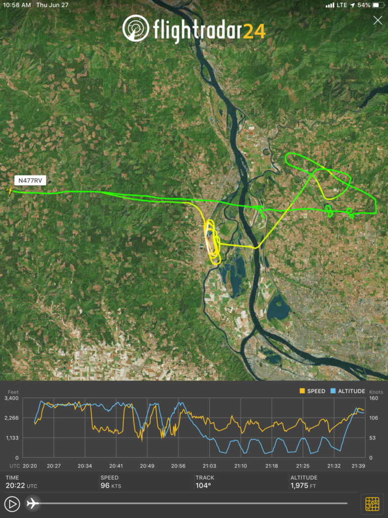
The second flight on 26 June consisted of air work – steep turns, slow flight, power off/on stalls – and several touch-and-gos at Scappoose. N477RV had only recently been updated with an Advanced Flight Systems glass cockpit including ADS-B Out and In.

The RV-7 is easy to fly, but there’s definitely a learning curve when transitioning from a slower, less-responsive airplane. Control forces are significantly lighter, and gentle nudges on the stick quickly replace larger movements used on garden-variety Pipers and Cessnas. The RV is less speed-stable than I expected – a known characteristic – so Mike teaches trimming for pitch attitude rather than speed and that seems to work well. Stall characteristics are fairly benign, with a slightly sharper break but fast recovery with pitch reduction and/or power addition. Rapid application of power at low airspeeds can produce pronounced torque roll which was an eye-opener at first, but I quickly became used to it. Power-off descent rates are relatively high, in the vicinity of 800 feet per minute in this airplane equipped with a constant-speed prop.

I’m a relatively low-time taildragger pilot, but I found the RV-7 easier to land than the Citabria I’ve been flying. The RV’s large rudder requires less movement to keep the airplane pointed in the right direction, and its wide-stance landing gear and low wing make crosswind landings less challenging than the Citabria.

27 June first flight

After ten stop-and-gos at SPB, I was pretty much cooked for the morning of the 27th. Fortunately, Mike had me scheduled for flights right after breakfast and lunch each day, so I had a lot of time in the afternoon to relax.

27 June second flight

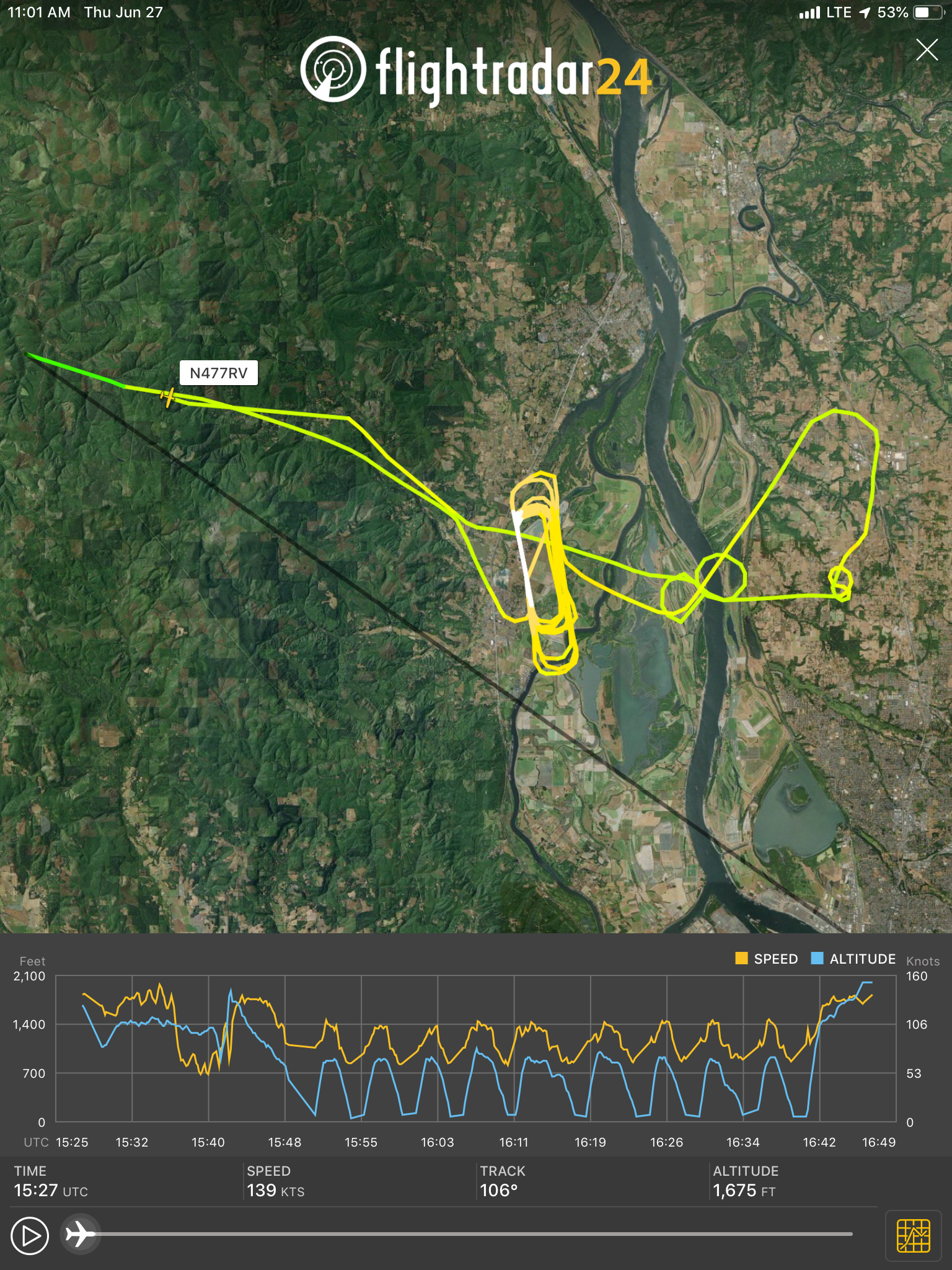
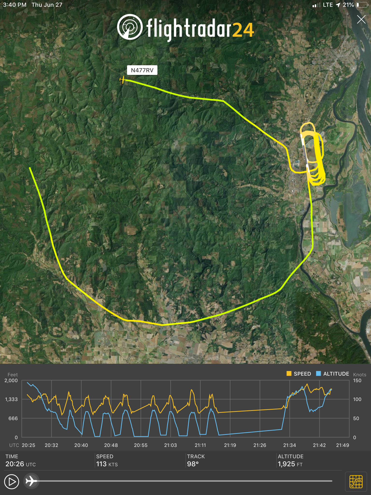
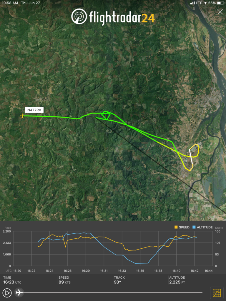
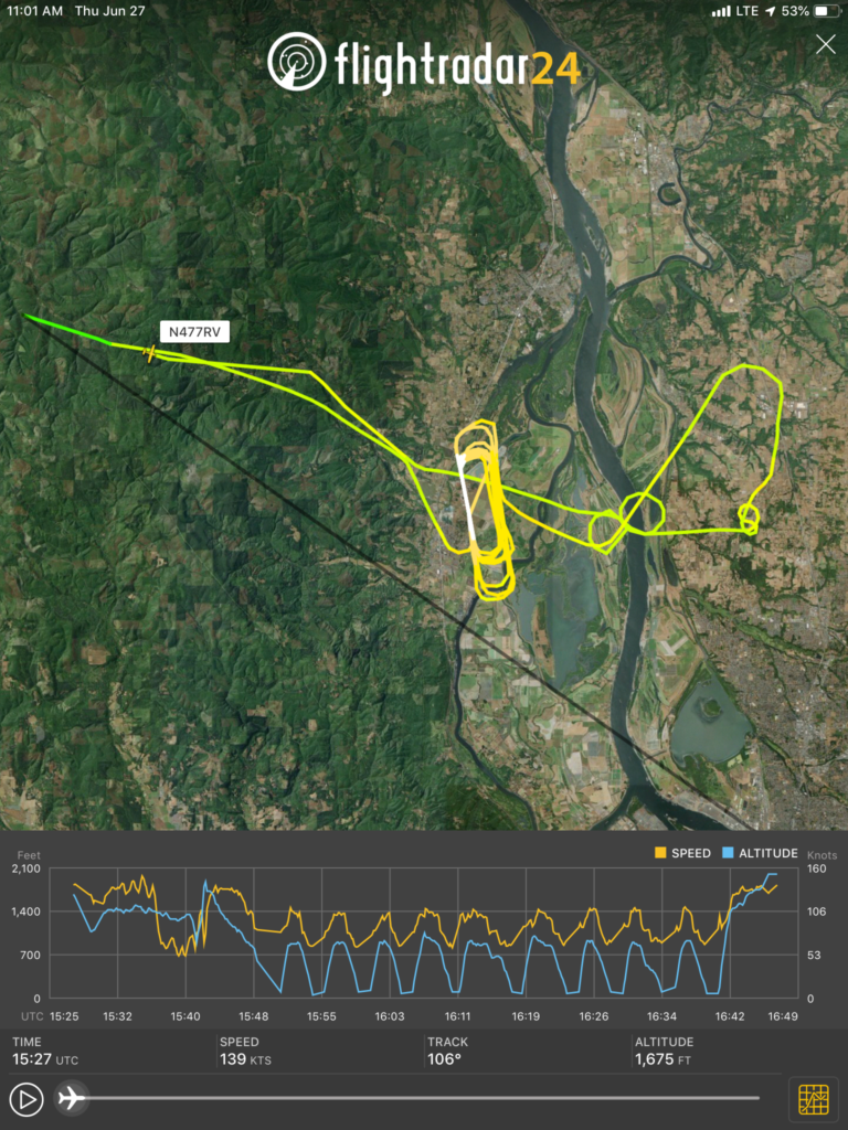
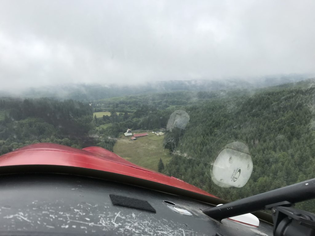
Weather on the afternoon of 27 June was challenging…there were showers and thunderstorms moving through the area so we took some detours to stay legal as we worked our way back to Vernonia.

Marginal VFR

Blah

28 June first flight

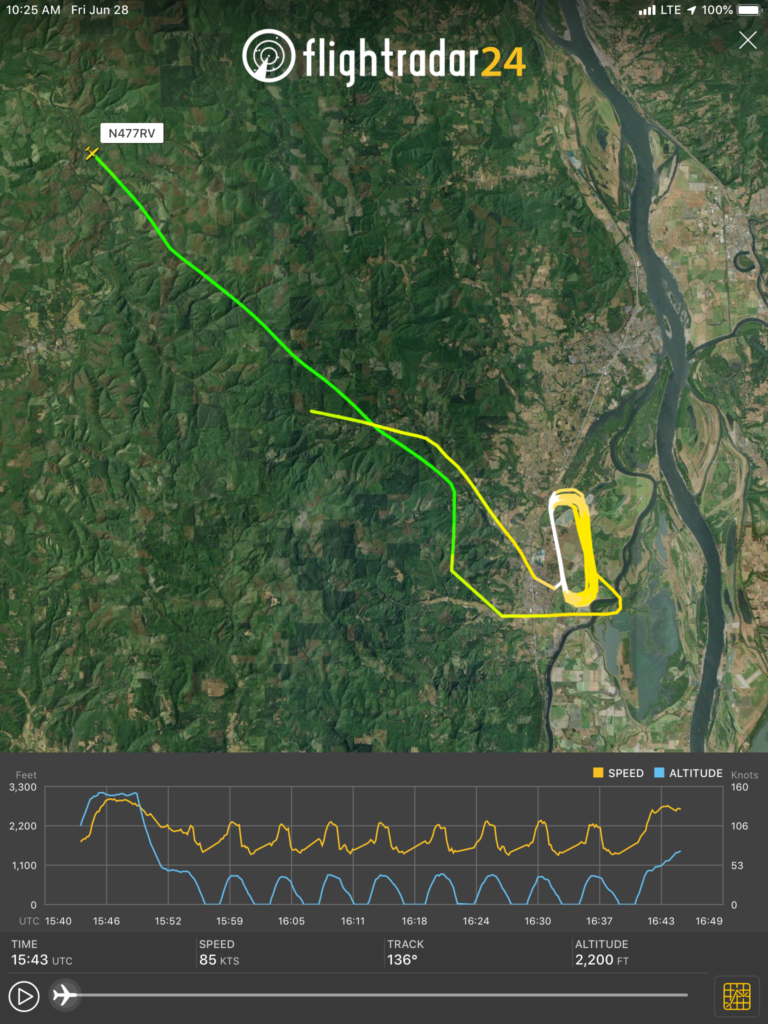
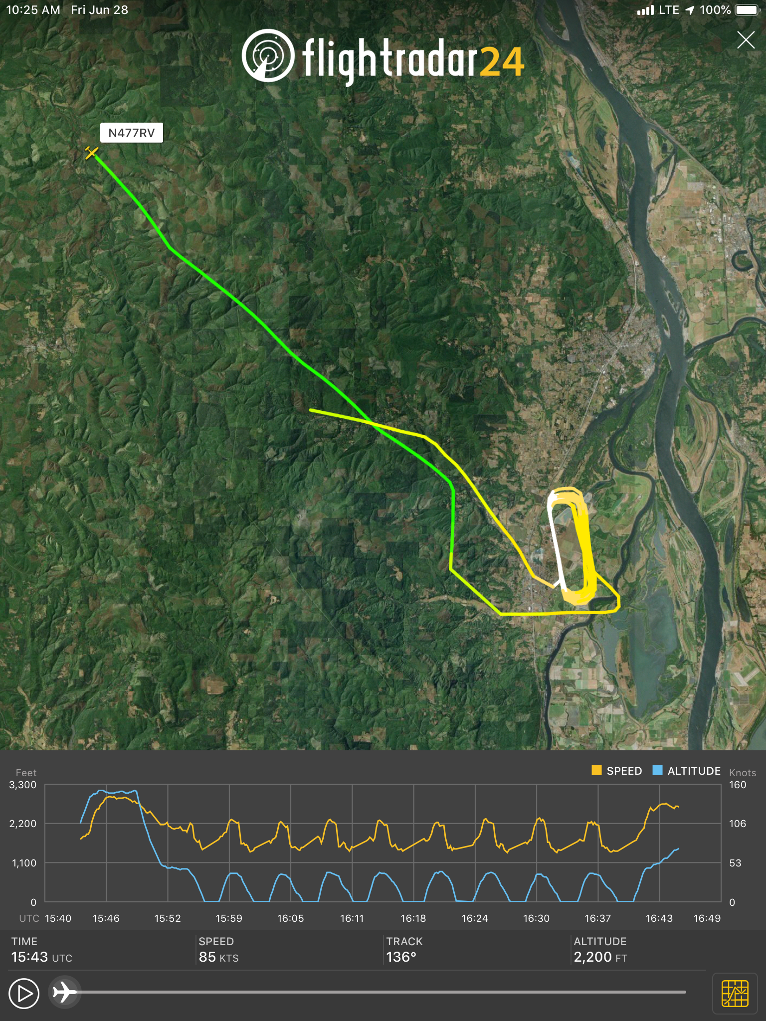
Lots more touch-and gos on the morning of 28 June. At this point I thought I was improving nicely, but the afternoon was to prove me wrong…

28 June second flight (1)

28 June second flight (2)

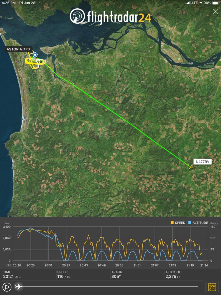
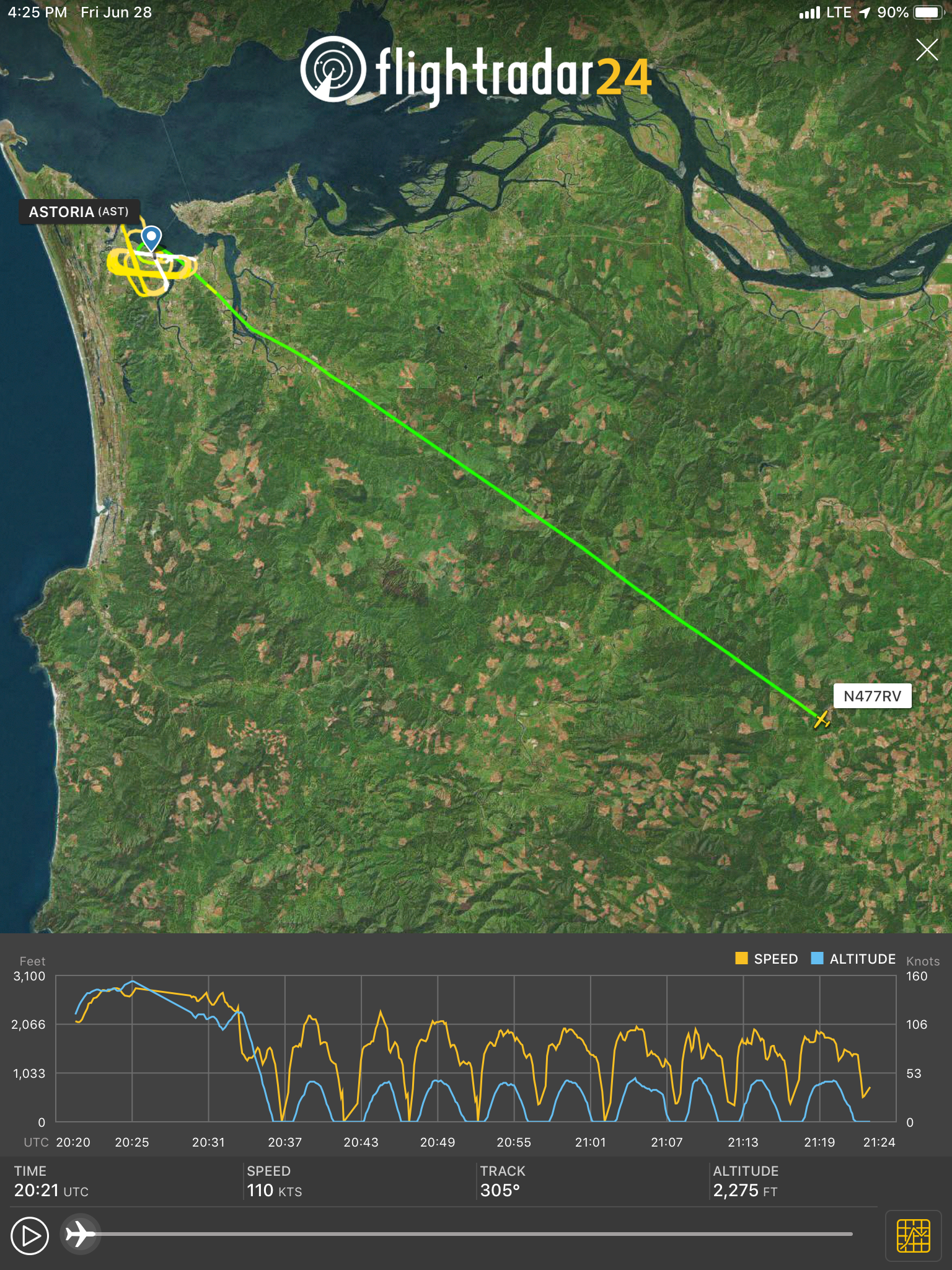
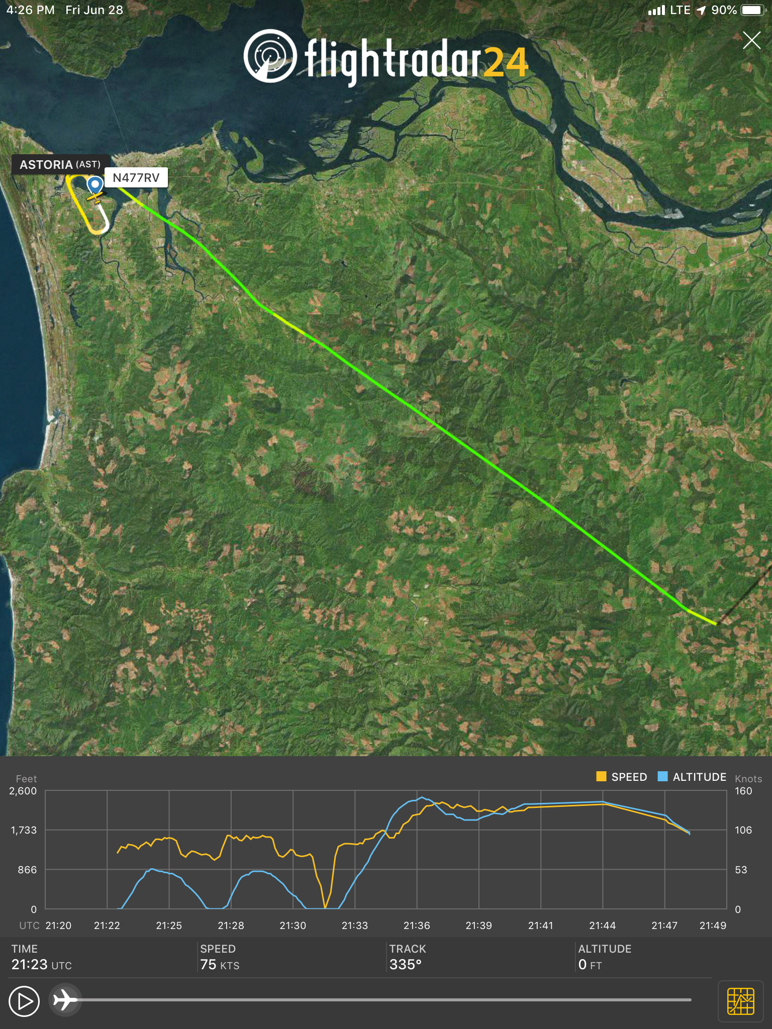
We headed over to Astoria (KAST) for some crosswind landings on the last flight of my transition training. I can’t say that these were the best landings I ever made, but Mike patiently worked me through my mistakes.

The RV grin
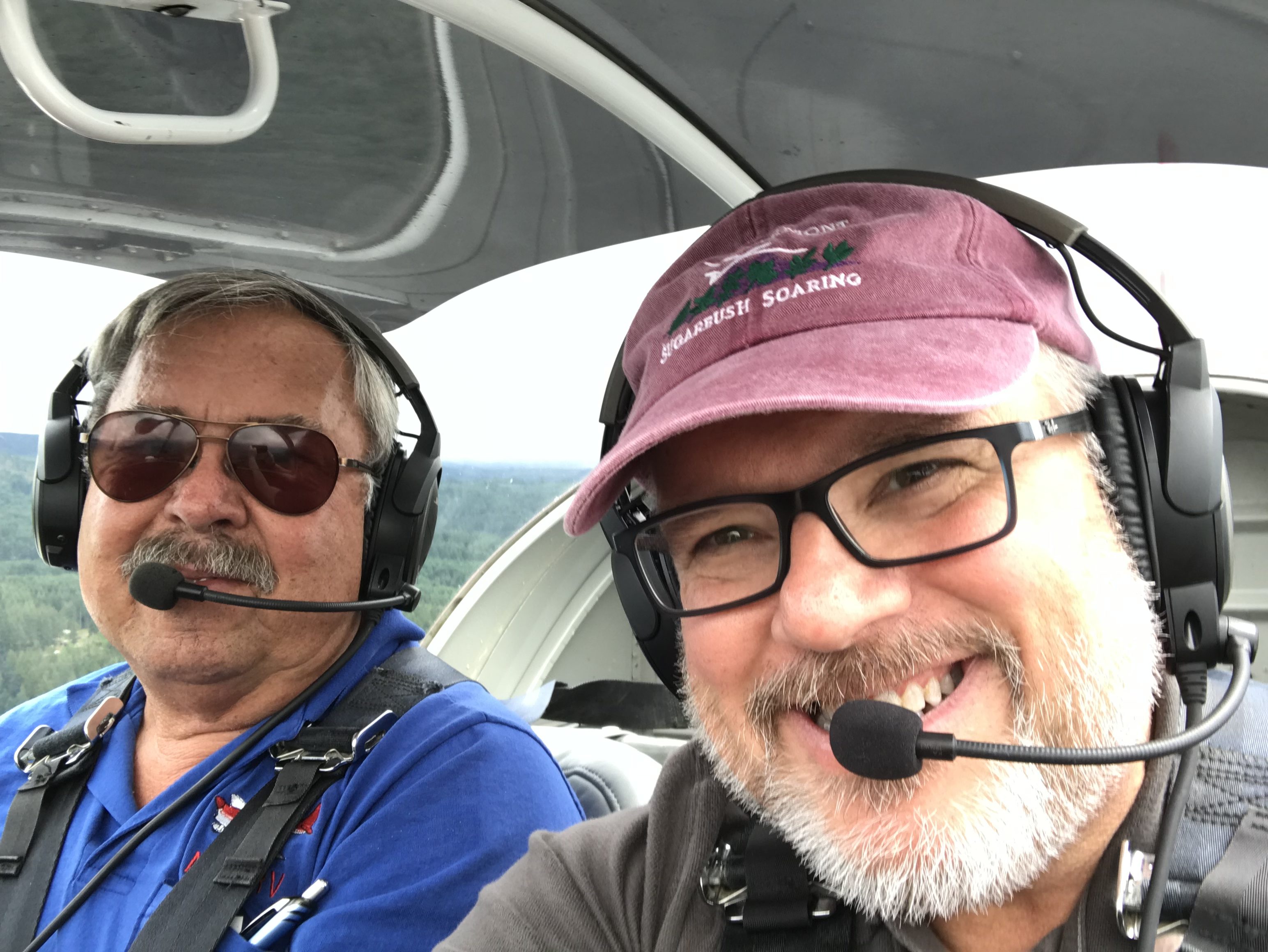
My RV grin is in full force. Mike is a wonderful instructor – patient and easy to work with while training to high standards. I’m certain that I’m not the best student that Mike has ever had, but I’m pretty sure I’m not the worst and I definitely felt very comfortable flying the RV-7. I couldn’t wait to get back and finish up the Mighty RV!

Back to the wings

I’m working on preparing the wings for final installation, and one task that’s easier to perform now is installation of the Garmin GSA-28 autopilot roll servo. Nothing too tricky here, the G3x installation manual covers the process nicely. I’ve had this servo sitting around for a couple of years and it took a bit of searching to find the necessary parts.

Roll servo mostly installedOne gotcha…in the past, Garmin claimed that their servo was compatible with mounting brackets from other manufacturers but that turned out not to be the case. I had originally installed an Advanced/Dynon servo bracket, because way back when I built the wings I was planning to use their avionics.

Turns out that the Garmin servo *isn’t* compatible with Dynon’s brackets, so I had to swap it for the one from the GSA-28 install kit. This won’t be a big deal for anyone who’s installing a servo from scratch, but if you’re swapping from another manufacturer, be prepared for a little extra work.

Full flaps

Continuing on with avionics and cockpit wrap-up, I had to install a microswitch that tells the angle-of-attack (AoA) computer when the flaps are down. Flap deployment changes the coefficient-of-lift curve and so for the AoA computer to work properly, it needs to know when the flaps are down.

Where the flap-down switch resides

The only place I could think of for the switch was right at the front of the flap arm, which is at its lowest point when the flaps are up. I thought I’d do something really spiffy and adjustable…

Flap-down switch, first attempt

…but that didn’t work so well because the bracket (dark grey thing with the black switch attached) was too long and interfered with the elevator pushrod.

Flap-down switch finalGoing back to the drawing board, I put a 90-degree bend in the bracket and rotated the switch so that it’s activated by the flap arm clevis. Works great, and there’s enough play in the switch that I can adjust it later if necessary.

Turns out that was the easy part. This switch grounds a wire coming from the AoA computer, so I had to run a wire from it to the central ground block in the elevator pushrod tunnel. That took most of an evening, but it’s done and the AoA computer now shouts “flaps” through the intercom when the flap-down motor is activated.

Flap motor installed

And here’s the installed flap motor with a Deutsch DTM connector all ready for plugging in to flap power and position sensor inputs for the GEA-24 and GAD-27.

Tunnels and pumps

I found that all the wiring I’d run between the instrument panel and cockpit center section just wasn’t going to fit in the “tunnel” that covers up wiring, brake lines (for nosedragger RVs) and fuel lines running from the firewall and instrument panel to the fuselage center section. I had to modify the tunnel cover to relieve the 90-degree angle at its forward end and so create more room for wiring.

Tunnel angle

This bit of aluminum turns the tunnel’s 90-degree bend into two 45-degree bends and creates more room for wire.

Tunnel angle installed

Another picture? Sure!

Modified tunnel

That solved one problem in this area, but I still had another one – as I ran wiring from the tunnel to the center section I forgot to leave room behind the fuel selector for the J-shaped tube that connects it to the fuel filter/pump assembly. Oops.

OopsThe solution was to fabricate a bracket that moves the pump/filter up and forward enough to accommodate an L-shaped fuel line that doesn’t interfere with the wire bundles behind it.

Fixing the oopsThe bracket attaches to the existing pump mounting holes in the tunnel cover. This created a challenging fuel line run from the pump outlet to the firewall but Tom Swearingen at TS Flightlines solved the problem with a well-crafted flexible fuel line with a 90-degree fitting on one end.

Tom's fuel lineThe end result – a tunnel that fits nicely in the fuselage and a pump/filter that connects nicely to the fuel selector.

The finished tunnel

Trimming the starboard stabilizing ailertooters

I have an unfortunate tendency to communicate in movie quotes, so bonus points to you if you can identify the “starboard stabilizing ailertooter” reference without using Google, Bing or some other internet search megalith.

No, the Mighty RV doesn’t have ailertooters but it does have ailerons and that’s what prompted the title. One of the last bits of cockpit work is installing the aileron trim motor; I fitted the bracket way back when I was building the fuselage center section and all that was left was to install the motor and connect it to the flight controls.

Aileron trim installed

I didn’t take any in-process pictures, so all you get to see is the final product. The trim motor is under the square white bracket in the lower center of this picture. It drives a lever that’s connected to the control sticks with springs which are adjusted to be in just enough tension that the motor can move the sticks but not significantly affect roll control feel.

Drawing current

So after finishing almost all of the avionics wiring, I came across a little warning in the Garmin installation manual that their engine monitor unit may not be able to provide enough current to the boxes that determine the amount of fuel in the tanks – a bit of potential non-coolness. But I have a piece of parchment on the wall that says I know something about electrical engineering, so I decided to run a quick to check on Garmin’s warning.

Measuring fuel sender current

I popped the fuel level sender’s Deutsch connector apart, jumpered my multimeter into the power line and powered up the avionics. Voila…an accurate measurement of the sender’s current draw – 8 mA, which is significantly under the engine monitor’s max current level. Cool.