First RF

New telescopes have “first light”, the Mighty RV’s avionics had “first RF” today.

Pulling out for a clear view of the skyI powered up the panel – both GPS receivers came up in 3D differential, Sirius/XM is begging for a subscription, tower and ATIS on the comm radios, and there’s even ADS-B In traffic on the G3x to boot. Cool.

First RF

The end of Act 1

I decided that my time as an Air Force civilian was complete; it’s time to move on to Act 2. Lots of friends and family joined me for the retirement ceremony, including my friends and fellow QBs Don McPherson and Vince Orlando who joined me in a dram of the Blue Label.

Cheers!

My sister and her family flew in from Kentucky and we had a great time at a Sox game. The Sox obviously didn’t know that VIPs were in attendance and had the unmitigated gall to lose the game.

Jacob, Whits, Joshua and Elizabeth

A riveting partnership

My wife is awesome. And she rivets like a pro.

My riveting partner

We finished riveting the turtledeck…well, almost. There are three rivets left on each side that are gonna be a beeyotch to get, but that’s a problem to be solved tomorrow.

The riveted turtledeck

Looks good, doesn’t it? It was all Ellen.

Baggage bulkhead cover

We clecoed the baggage bulkhead in place because we could, and it looks cool.  Plus, it helps keep dirt and dust out of the tailcone.

Buttoning up the turtledeck

The tailcone avionics and electrical wiring are done and I really want to rivet the fuselage “turtledeck” skin – the one behind the cockpit. But I also don’t want to dive back there to fix wiring problems once it’s in place.

I’ve smoke-checked the ELT’s RS-232 data connection to the GTN-650, the tail nav/strobe light and even the elevator trim servo. But the last bit to be checked is the servo’s position indicator and the only way to know for sure is to configure the G3x Touch display to read and display position indicator signals. So that’s what I did.

G3x Pitch Trim 1

Configuring the Touch was a lot easier than I feared. All that’s required is to move the trim servo to full up, center, and full down and tell the display when the servo is positioned at each point.

G3x Pitch Trim 2

The Touch calibration page reads voltage coming from the position indicator and displays a gauge preview…very cool. That’s a good confirmation that the tailcone wiring is fully functional.

G3x Pitch Trim 3

And now Elevator Trim shows on the PFD…even more cool!

Turtledeck ready for riveting

A few more minutes and the turtledeck is clecoed into place for the last time and we’re ready to break out the rivet gun and bucking bars.

Current progress

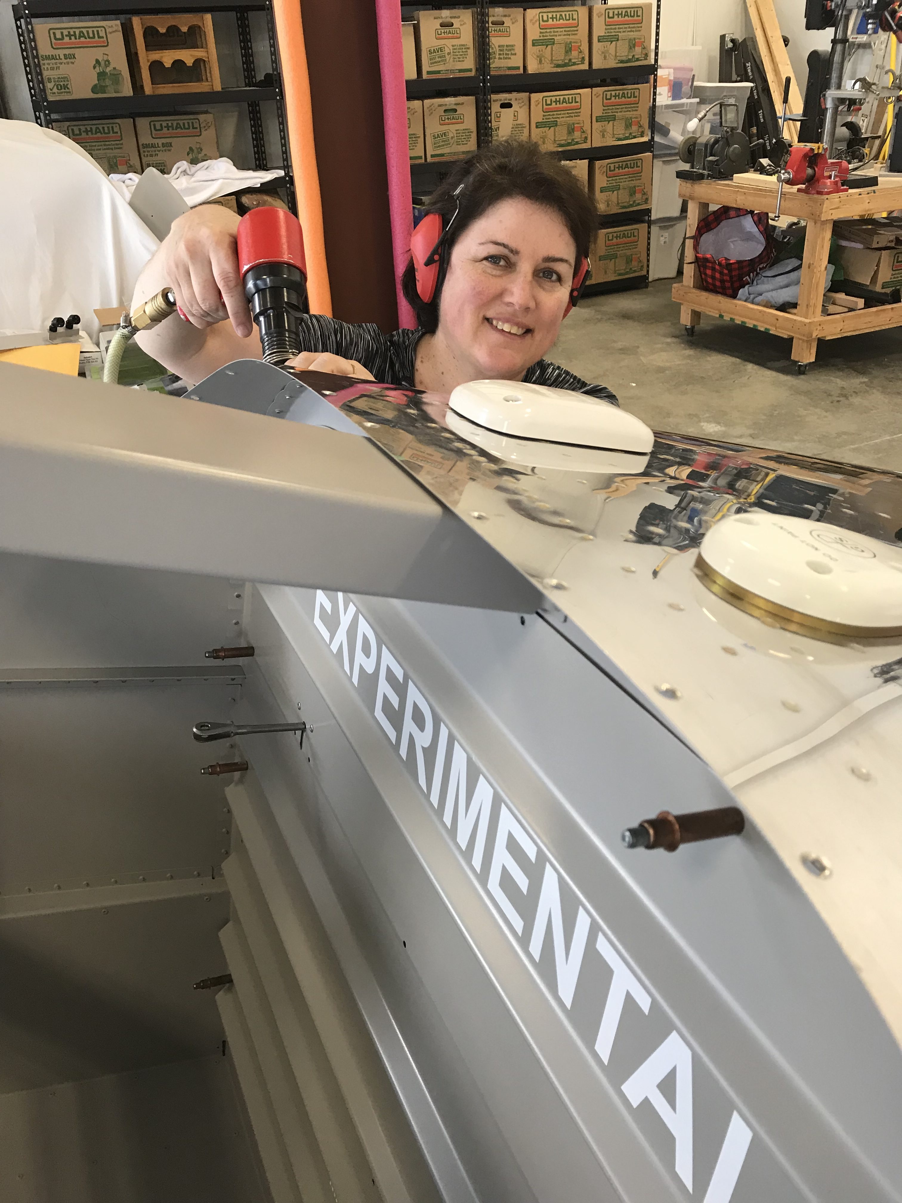
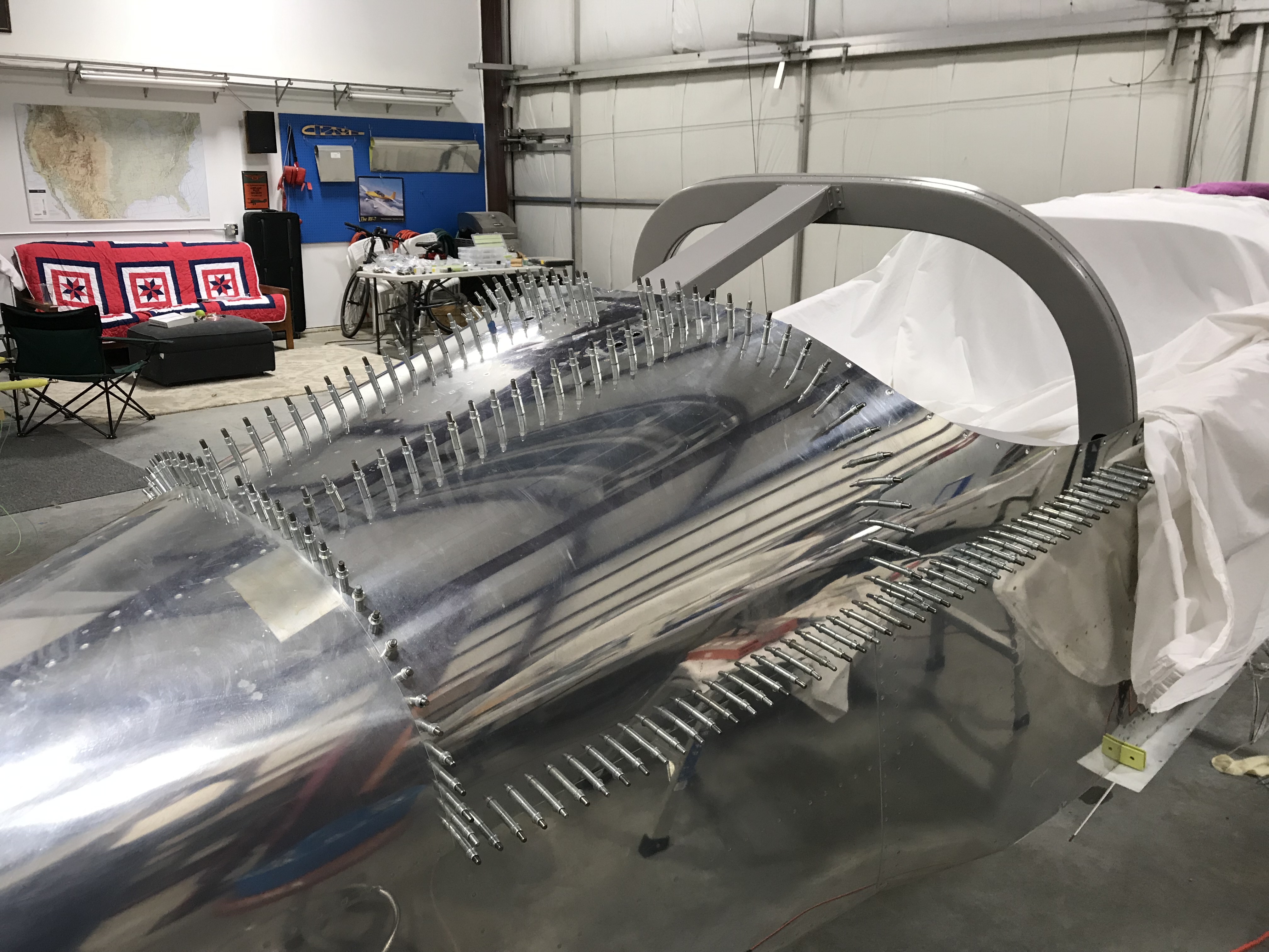
One of the cool things about this stage of the project is that after a few hours of wiring I can turn on some part of the RV’s avionics and see it work.

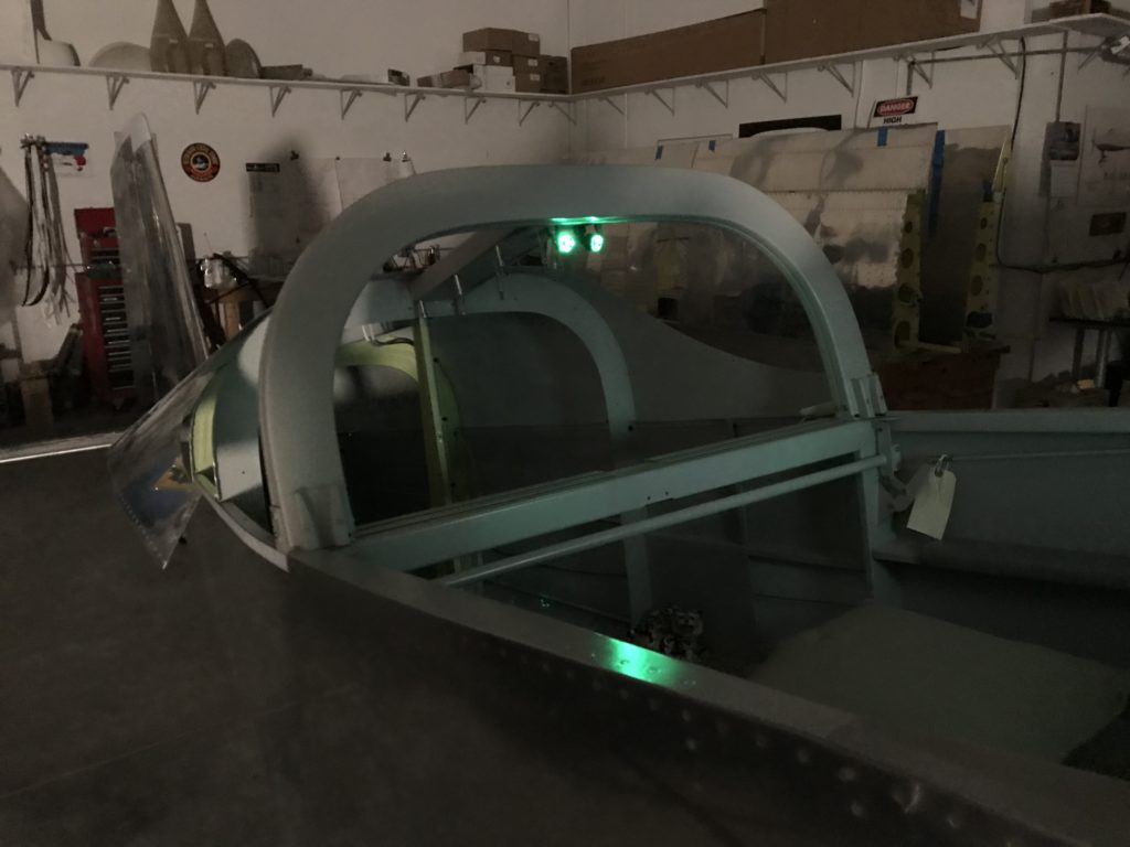
For instance, I’ve had these Oplite 6 LED lights for several years now and finally got them wired up to the Garmin GAD-27 as instrument panel lights, so they’re controllable by a dimmer on the panel. These lights are really rugged and when driven by one of the GAD-27’s PWM lighting controllers, they’re dead quiet too – no hash on the radio like I’ve encountered with some other dimmers. Very cool.

Panel lights

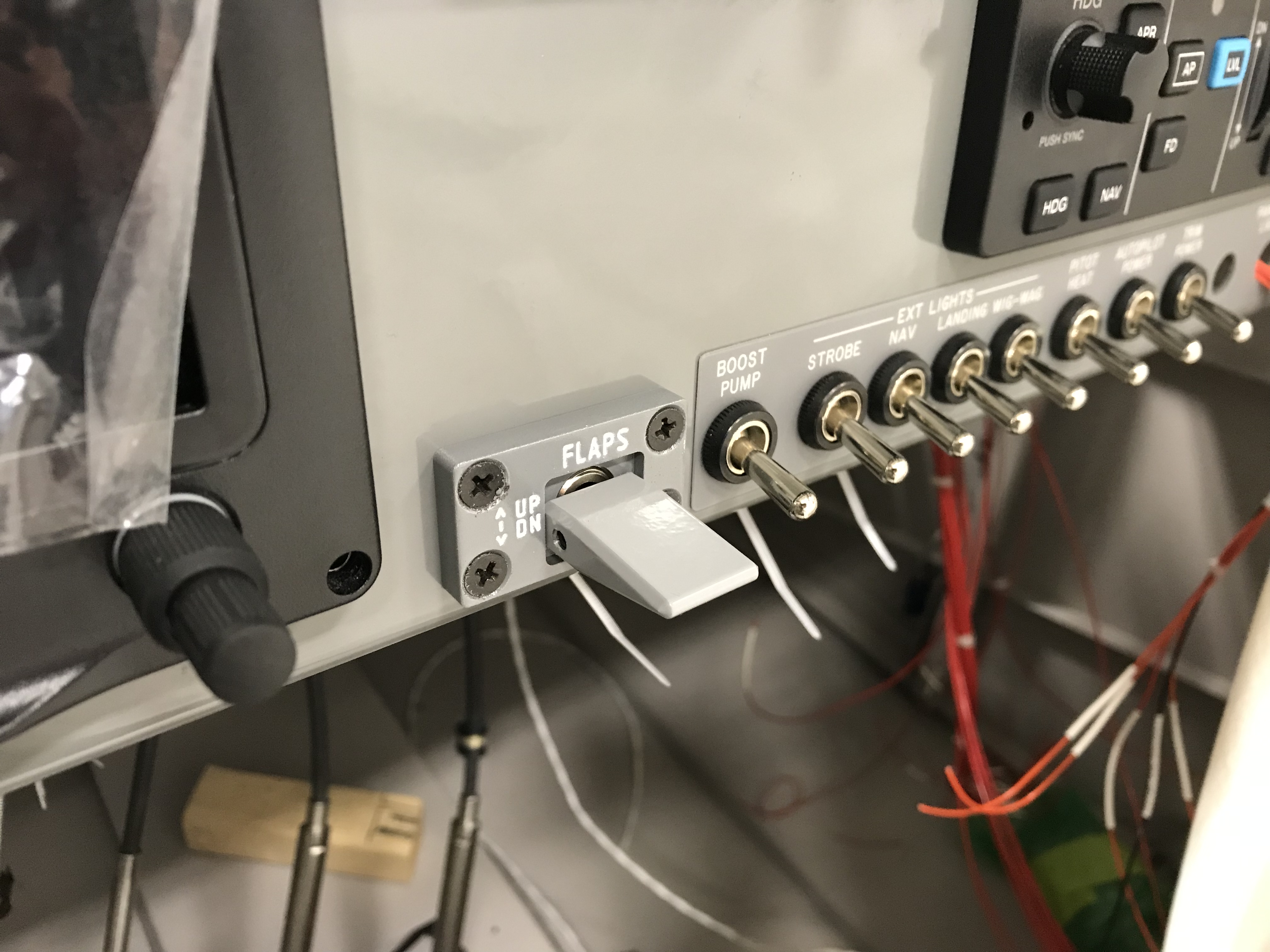
I’ve also had Whelen LED nav/strobe lights sitting around for a few years, waiting for installation. The tail nav/strobe is finally wired through to the cockpit, and here’s some video to show how damn bright they are…low current draw too, and no need for a heavy strobe pack like older nav/strobe lighting systems.

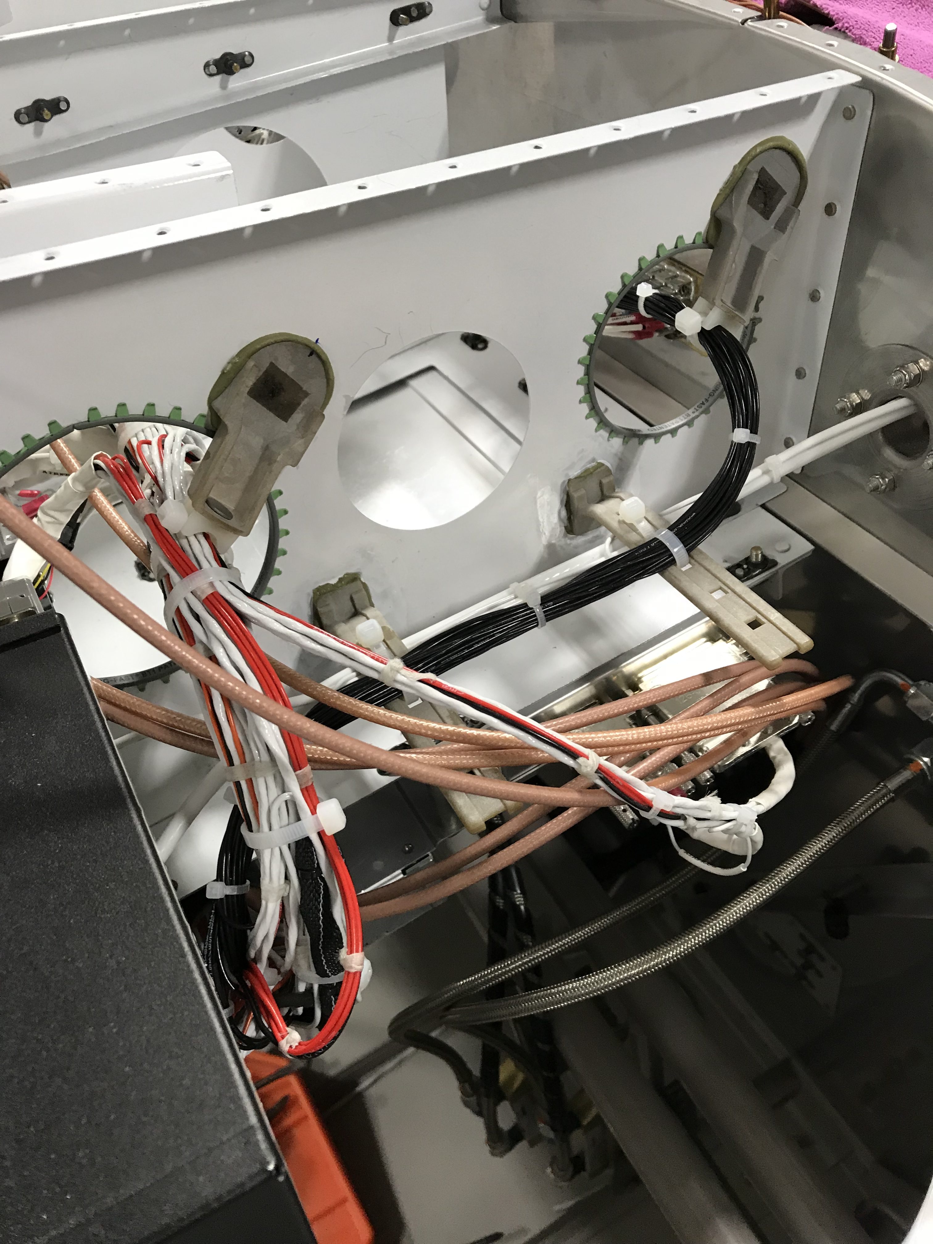
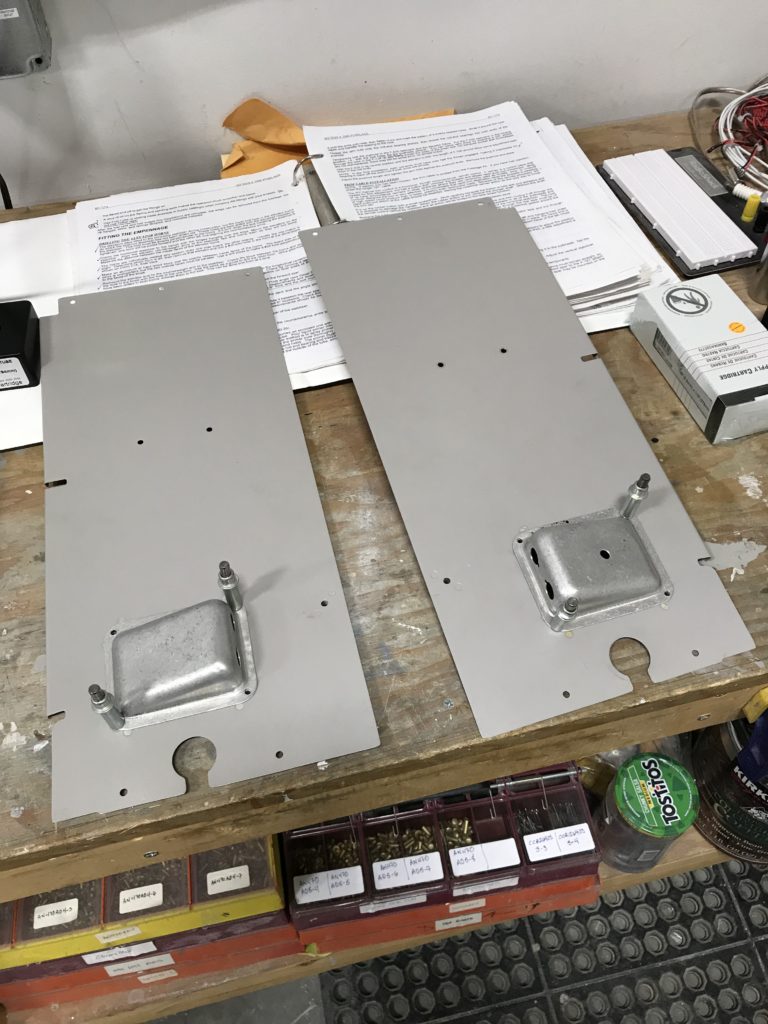
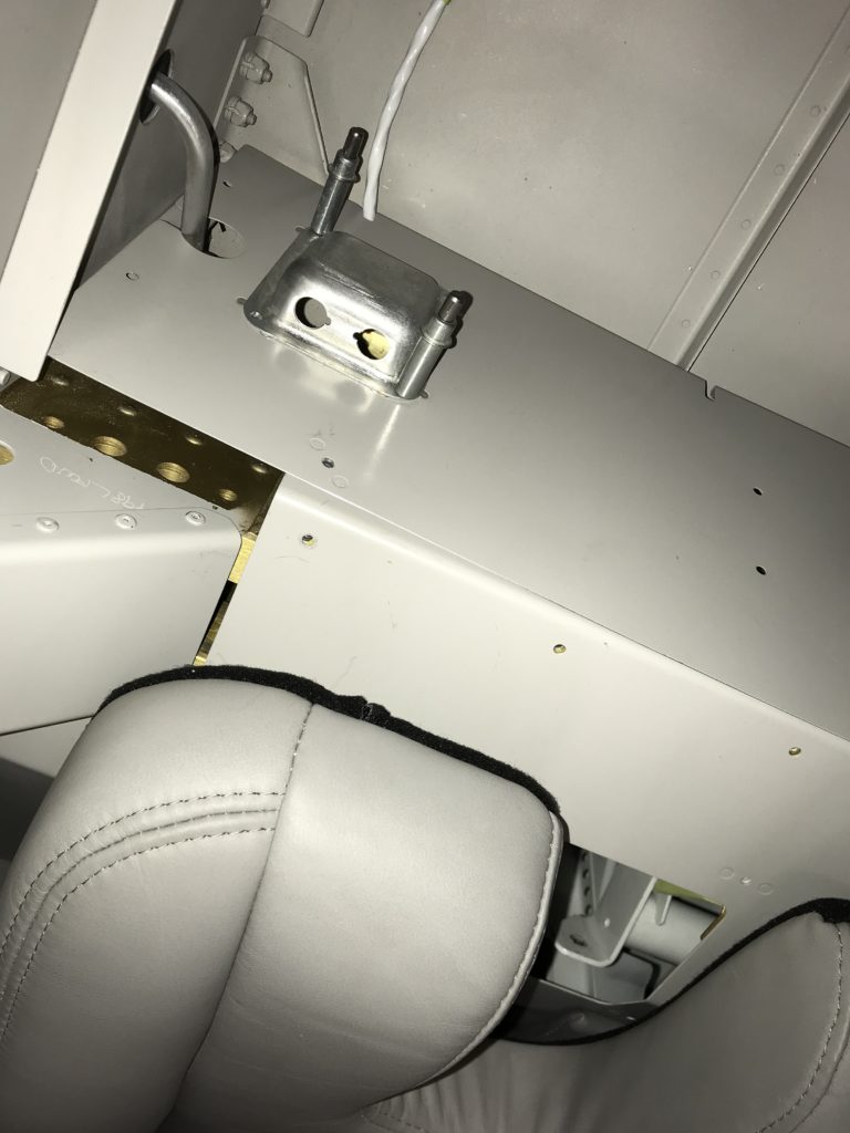
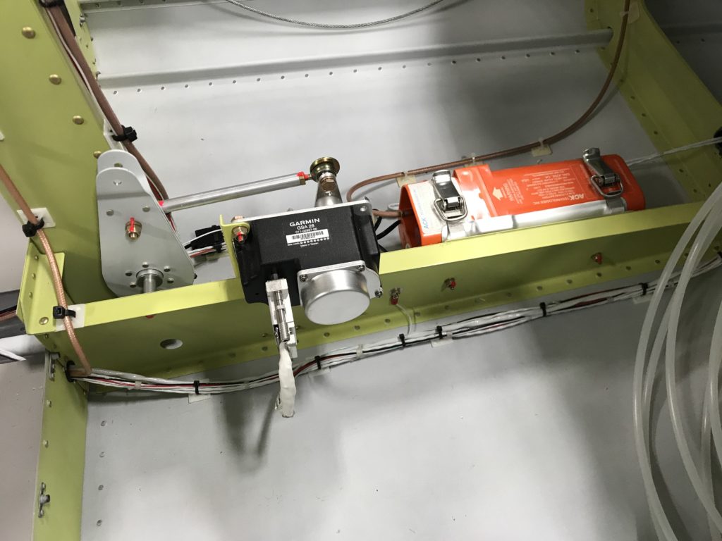
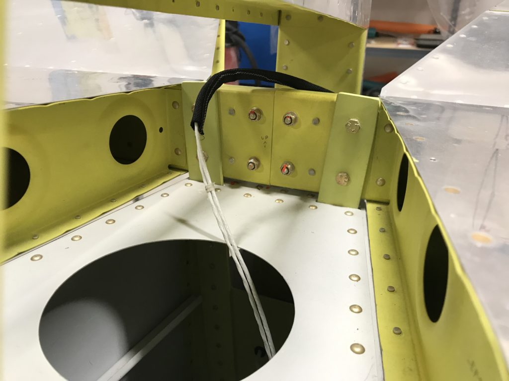
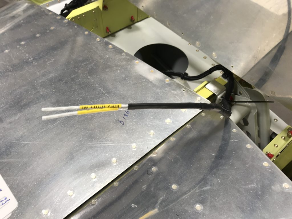
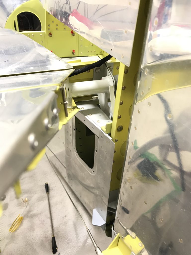
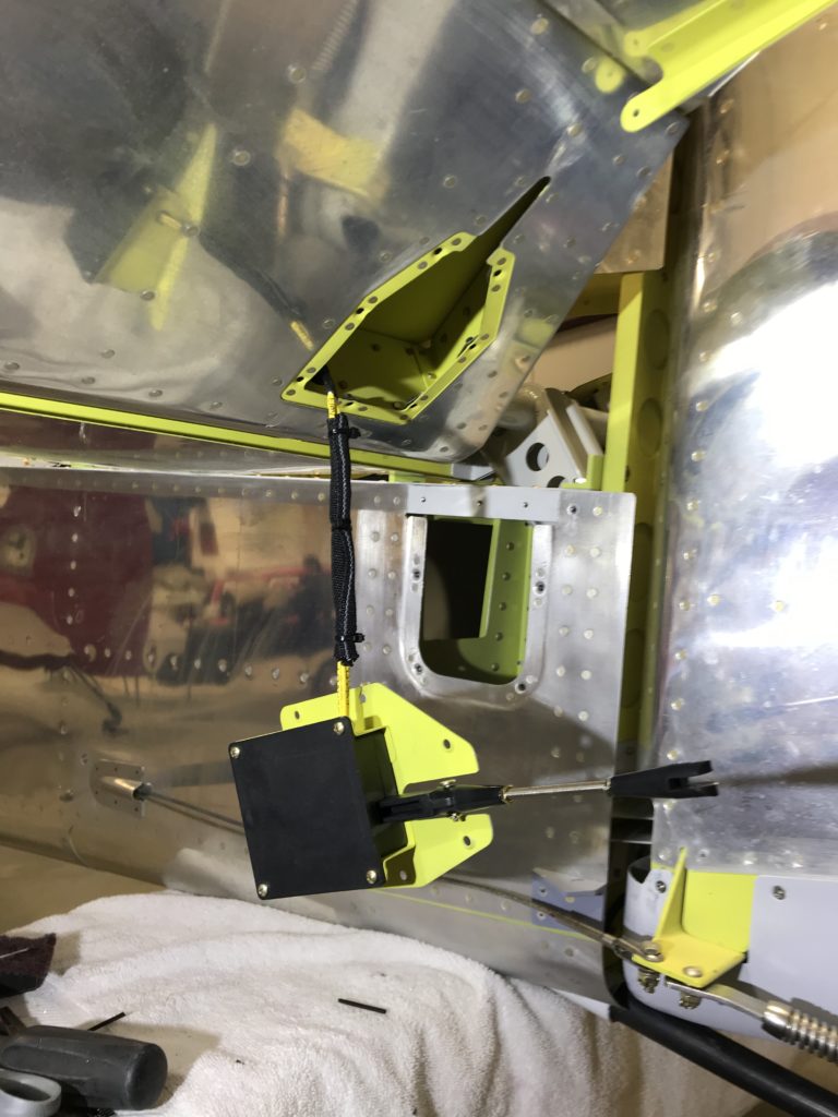
Next on the list was wiring the flap motor, but I need some hardware to fabricate a mounting bracket. So, I jumped ahead to wiring the Advanced Flight Systems Angle-of-Attack (AoA) system. This is the only “legacy” avionics system on the airplane, as Advanced doesn’t sell it anymore. I hope it doesn’t fail.

For those of you who aren’t into aerodynamics, AoA is the angle at which the wing meets oncoming air, thus generating lift. If AoA exceeds a certain value, the wing stalls and lift is drastically reduced – so you can see why knowing AoA might be important for staying in the air. If you’re really into the concept, watch this video.

AoA is alive!

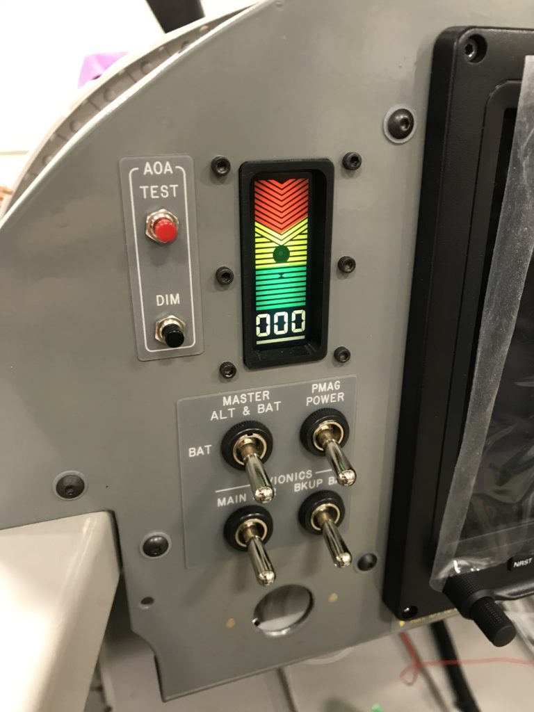
Everything lights up, and the self-test lady says the system is working…

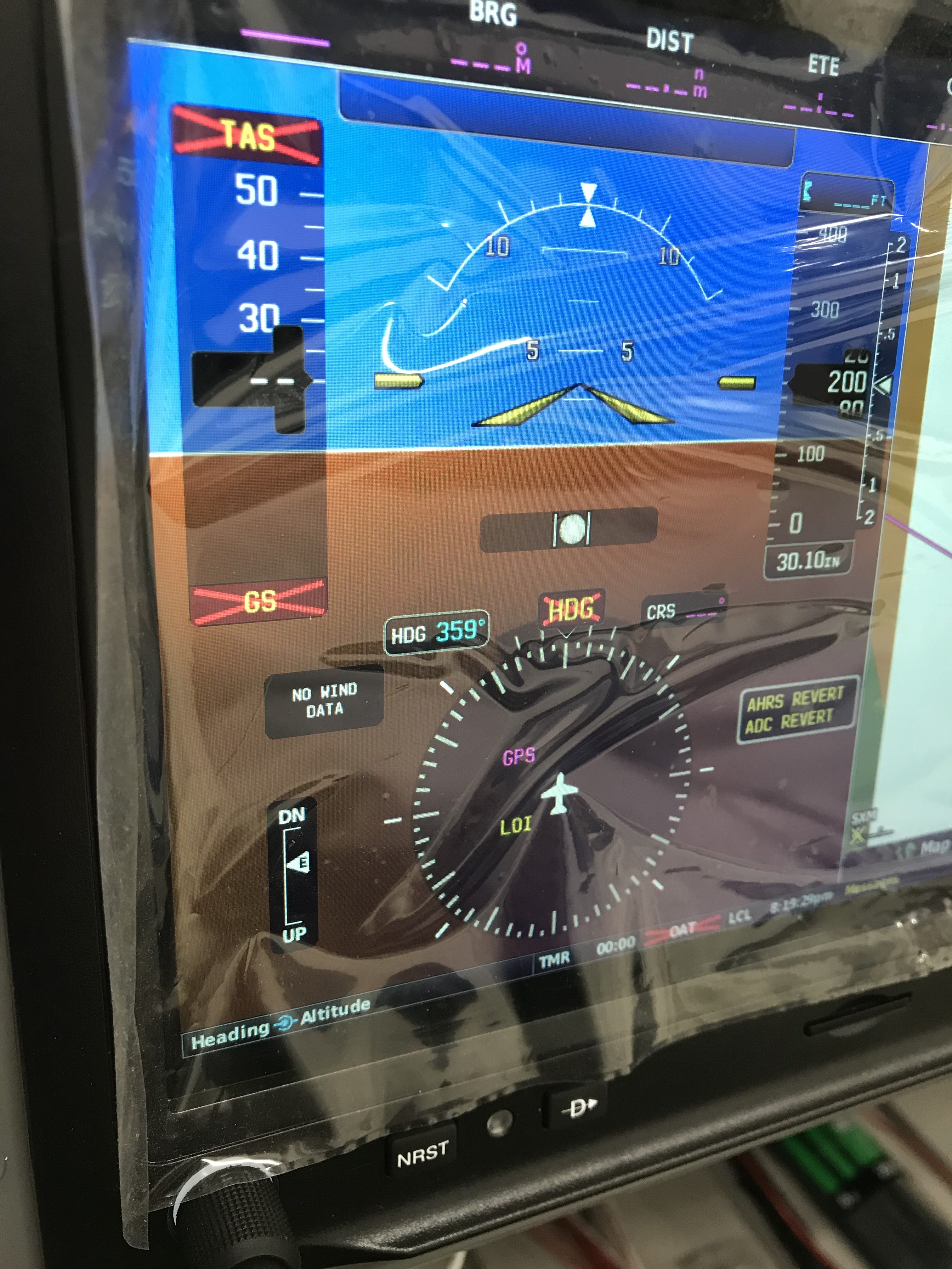
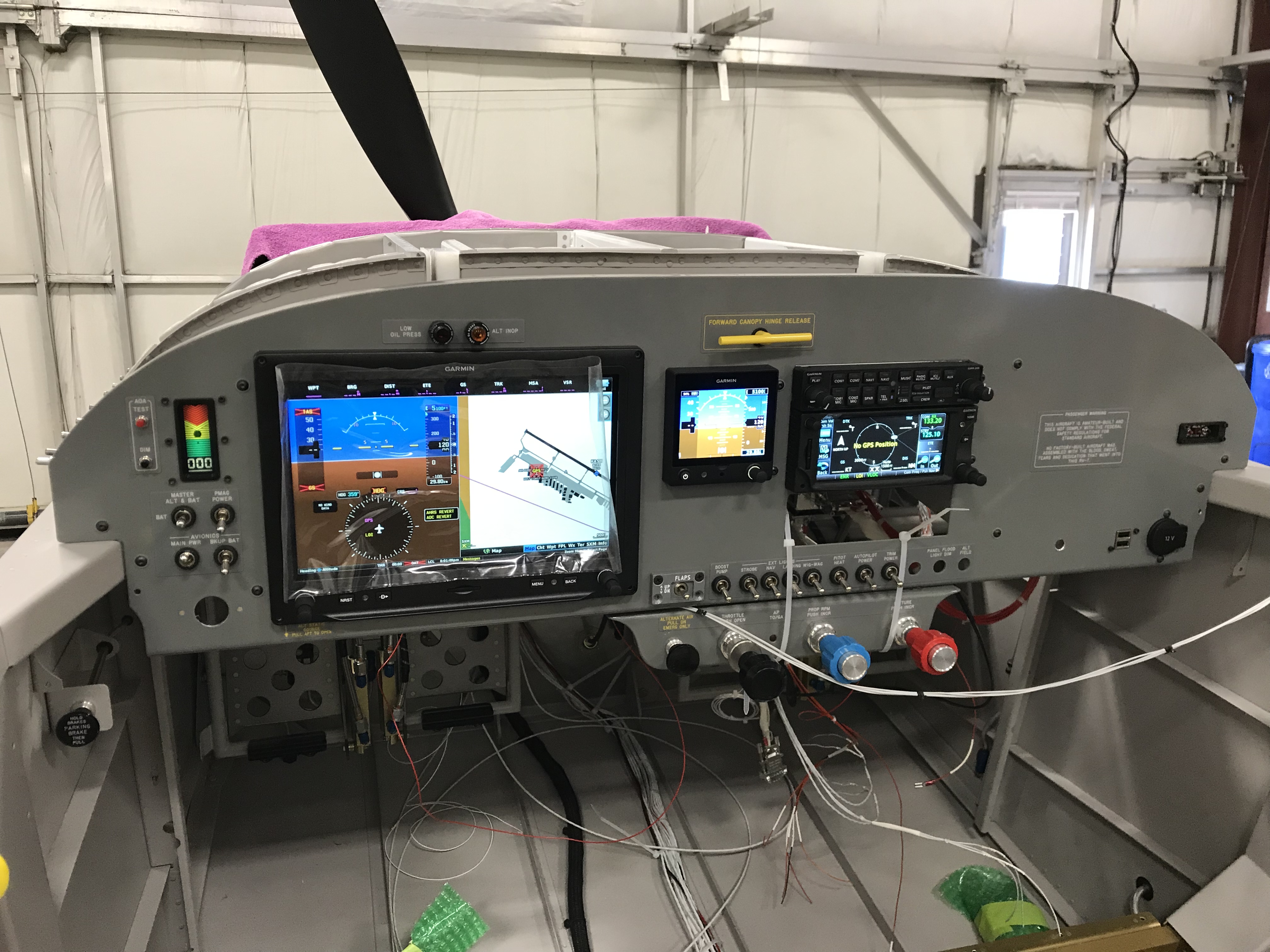
Of course with all the gee-whiz stuff lit up, I had to take a picture. Enjoy!
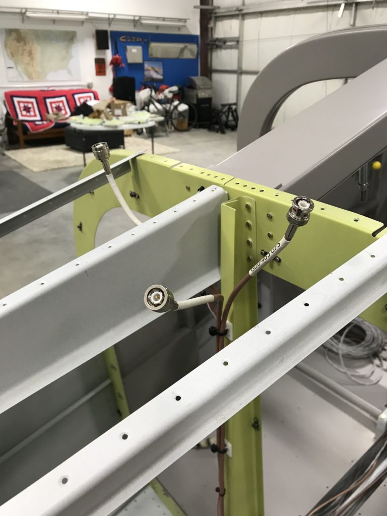
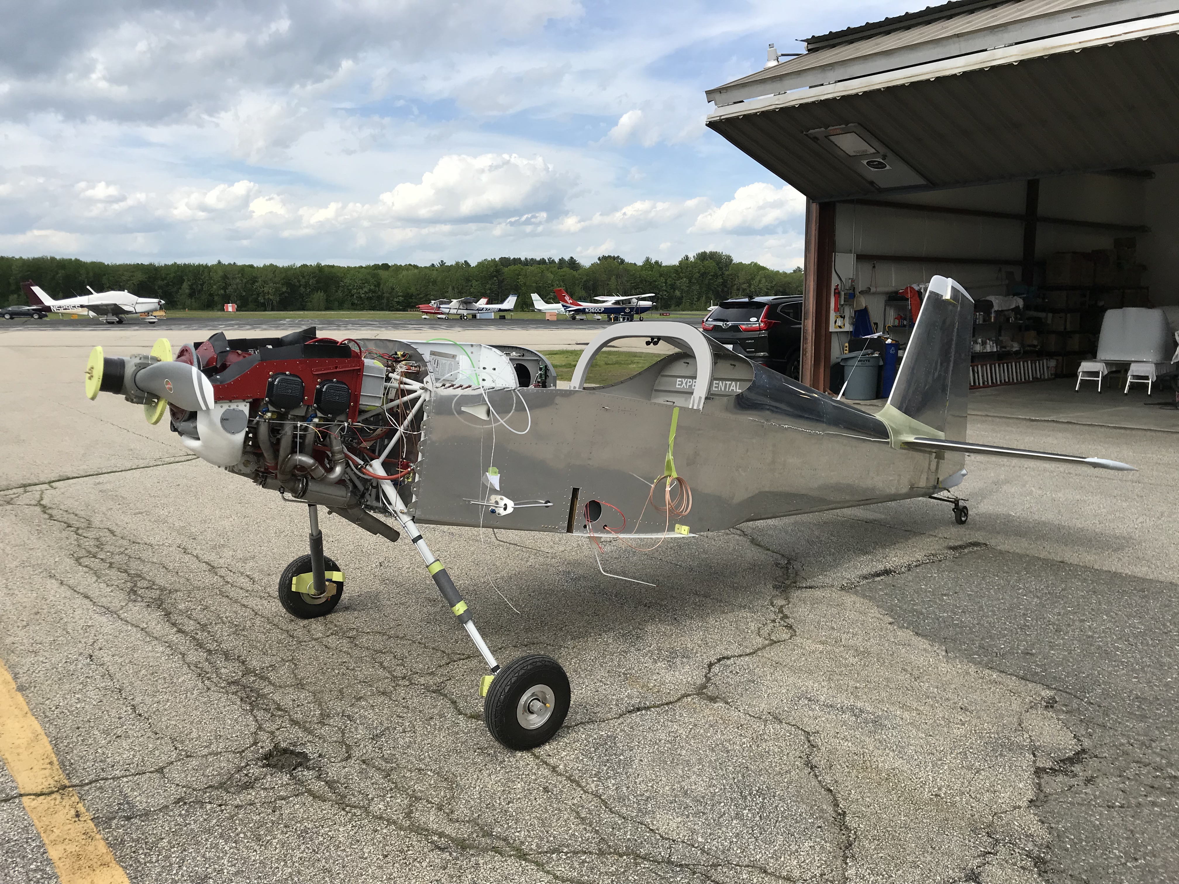
A thing of beauty

Locating audio system interfaces

I’ve been checking off some smaller tasks from my to-do list, one of which is figuring out where to mount the Pilot and Co-Pilot headset jacks. I didn’t want them hanging from the panel, so I put them on the cover plates in front of the wing spar bulkhead.

Mounting headset jack holders

These covers are sold by Aircraft Spruce, and they worked really well.

Pilot's headset jack

More wiring in the tail

Even more fun with wiring…working my way forward from the tail I routed serial data and power wires to the ELT and assembled the autopilot pitch servo DSub connector.

AP pitch servo and ELT wiring

I also ran coax to the GTN-650 GPS and G3x GPS/XM antennae.

GPS/XM and light wiring

Assembling coax connectors is fun, at least for me…

GPS/XM antenna connectors

More to follow as I work my way forward to the cockpit.

Wiring from the tail forward

There isn’t a super-convenient way to route pitch trim and magnetometer wires into the empennage, so I improvised…

Here’s the pitch trim servo wire exiting through a lightening hole in the fuse rear deck.

Routing the pitch trim wire

I liberally applied adhesive zip-tie mounts to the rear deck and glued a small piece of aluminum angle to the rear spar with 3M 4000 marine cement (easier than riveting) to hold another zip tie.

Pitch trim wire over the HS sparThe black material is self-closing anti-chafe wire bundling I found at McMaster-Carr. The plans call for running trim wires along the front of the left elevator and into the trim servo bay. I think this is better than running wire through the existing manual trim cable holes as repeated elevator movement over time slightly twists the cable rather than bending it – much better from a wire fatigue/failure perspective.

Routing pitch trim wire into the elevator

You’ll see in this picture how the trim servo cable is routed into the left elevator and why some support is necessary where the cable crosses the HS rear spar.

Pitch trim servo ready for installation

And here’s the wired trim servo ready to be stuffed into the elevator. It’s slightly tricky to route the cable so it doesn’t interfere with the servo’s jack screw, but I think I’ve managed to get everything done correctly.