A happy New Years at the ThermosWorks

After more than 12 years, the rudder and elevators are mounted to the empennage and they’re moving freely without binding. Took a lot of fiddling with washers and spacers, and some expert help from my Tech Counselor (thanks Bob!) to make that happen, but it’s done.

Here’s a short demo of today’s work…

More fiberglass work on the tail

Just when I thought I was done with fiberglass work on the empennage, a problem with the tail strobe/nav light proved me wrong.

I’m using Whelen’s LED nav lights and the tail light is just a little wider than the lower rudder cap can accommodate. Time to get out the Dremel saw and do some surgery…

Butchering the lower rudder cap

I did a rough cut to accommodate the electronics end of the light, then wrapped the light in packing tape as a release agent for the fiberglass I laid into the cutout area.

A bit of sanding around the cutout and I was ready for BID and resin.

The end result…a nicely-faired tail light! I didn’t capture a picture of the modified fairing but the change is barely perceptible from the original installation.

The nervous system arrives

Back from Thanksgiving with family at Bear Ass Cove on Newfound Lake, New Hampshire and guess what UPS delivered? That’s right – the avionics harness!

Unboxing the avionics harness

I’m almost ready to install the harness – just a couple of empennage things left to finish – but I couldn’t resist stretching it out. This is, essentially, the Mighty RV’s nervous system and having it fabricated by the neurosurgeons at Approach Fast Stack is saving me a *ton* of build time. Cool!

The whole nervous system

A few tips

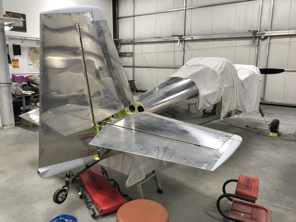
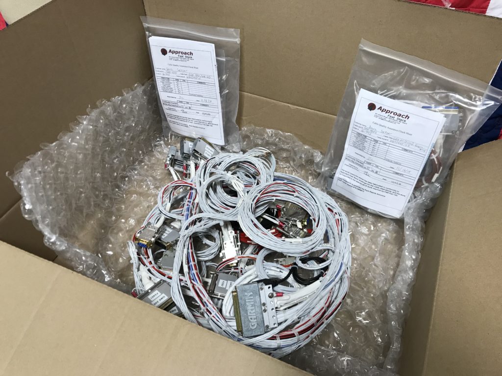
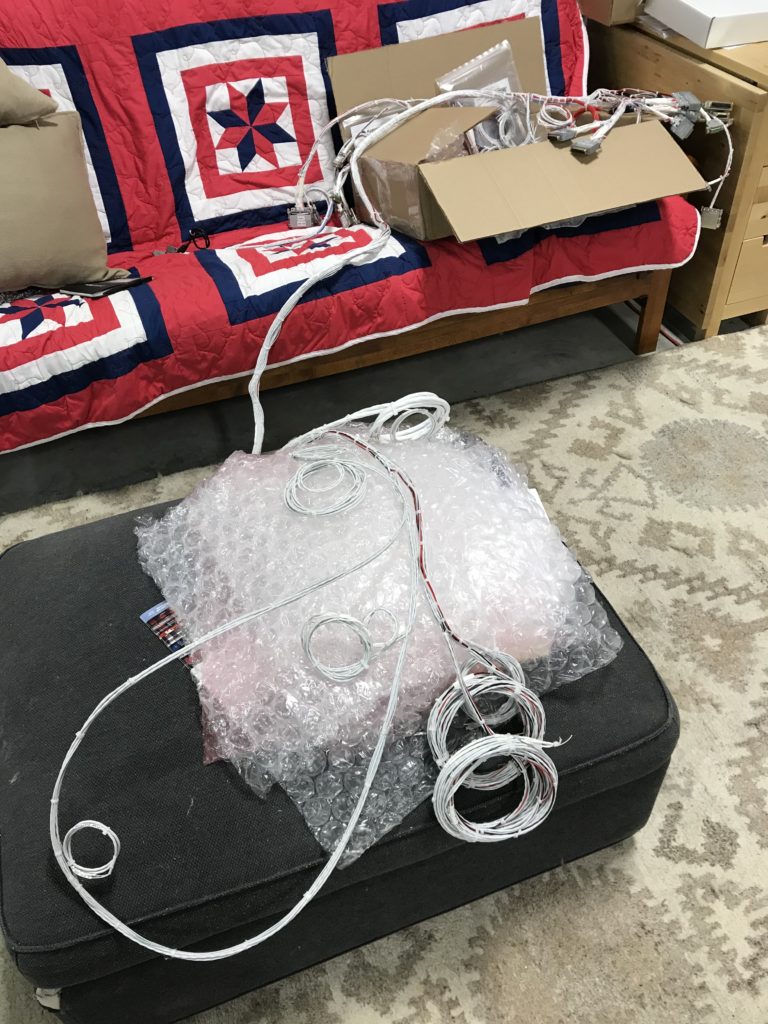
I’m awaiting delivery of the avionics harness from Approach Fast Stack so I decided to tackle a task I’ve been avoiding for more than 13 years – fitting fiberglass tips to the horizontal stabilizer, elevators, vertical stabilizer and rudder. I’ve said before that I hate working with fiberglass and that’s still the case.

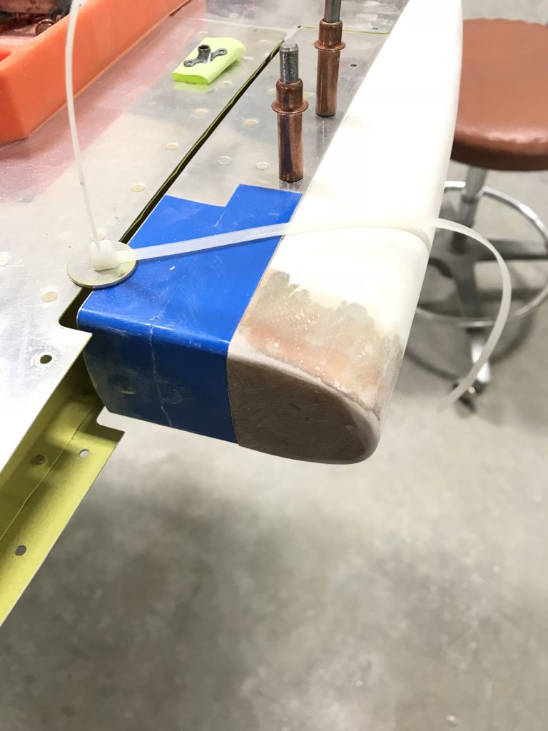
Van’s ships the elevator tips with no front end and recommends fairing over the counterweight with an epoxy/flox fill, essentially making it non removable. I decided to add a thin fiberglass layer over but not attached to the counterweight so that I can remove the tip later on if necessary.

Tip prep was simply sanding down the front surfaces to give the layup something to bond do.

Elevator tip prepped

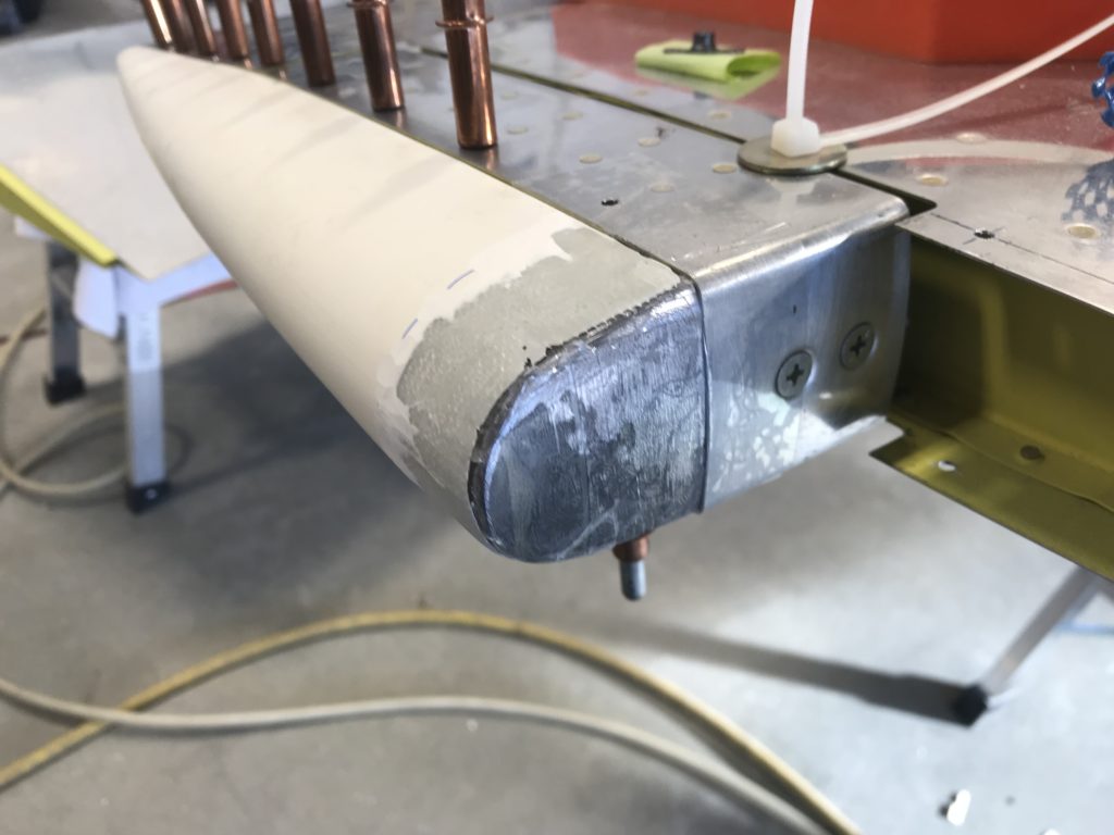
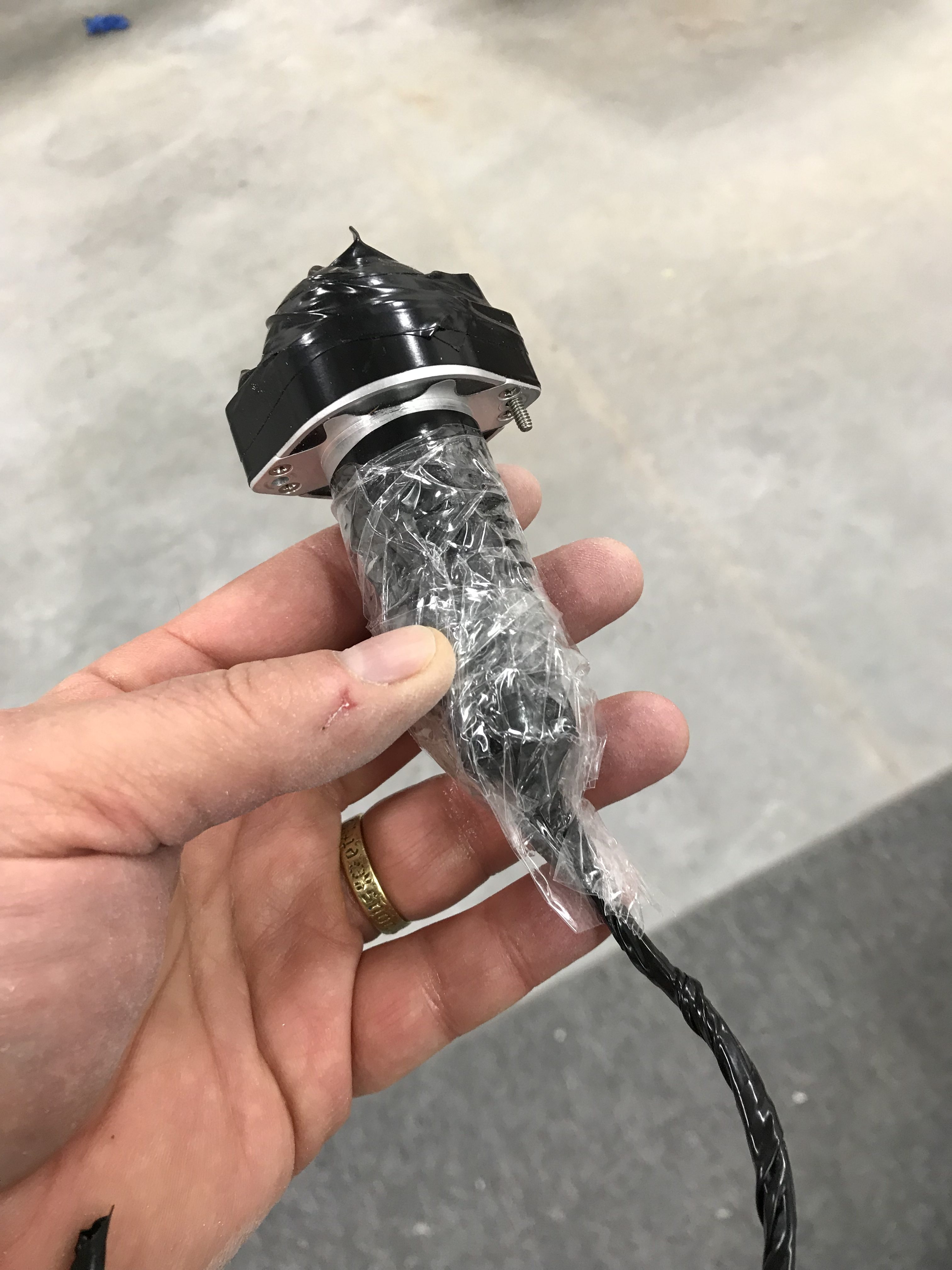
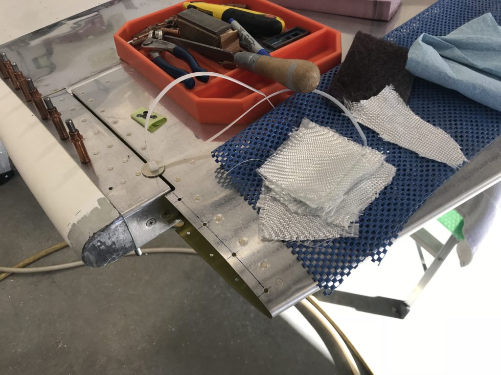
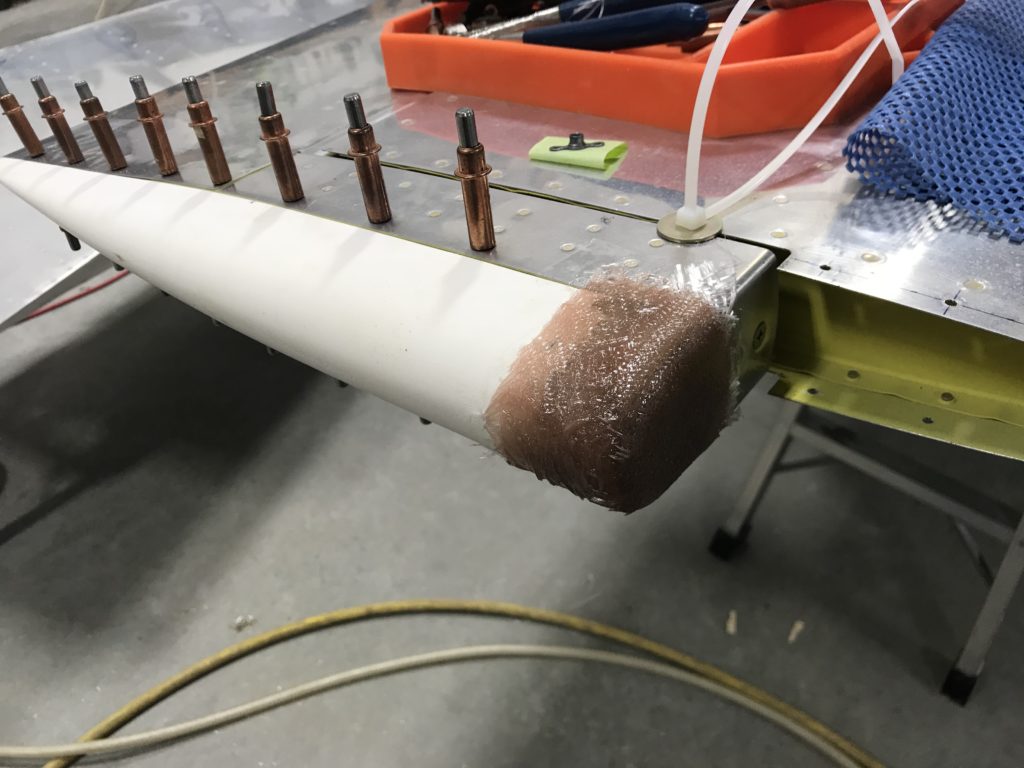
I laid up 3-4 layers of 9 oz BID cloth over the counterweights and front of the tip. Before doing that I covered the elevator and counterweight with clear packing tape as a mold release.

Fiberglass ready to apply

The layup initially looked too thick but when I sanded it down to match the elevator and HS tip there wasn’t much left – but there really doesn’t need to be.

Initial fiberglass layups

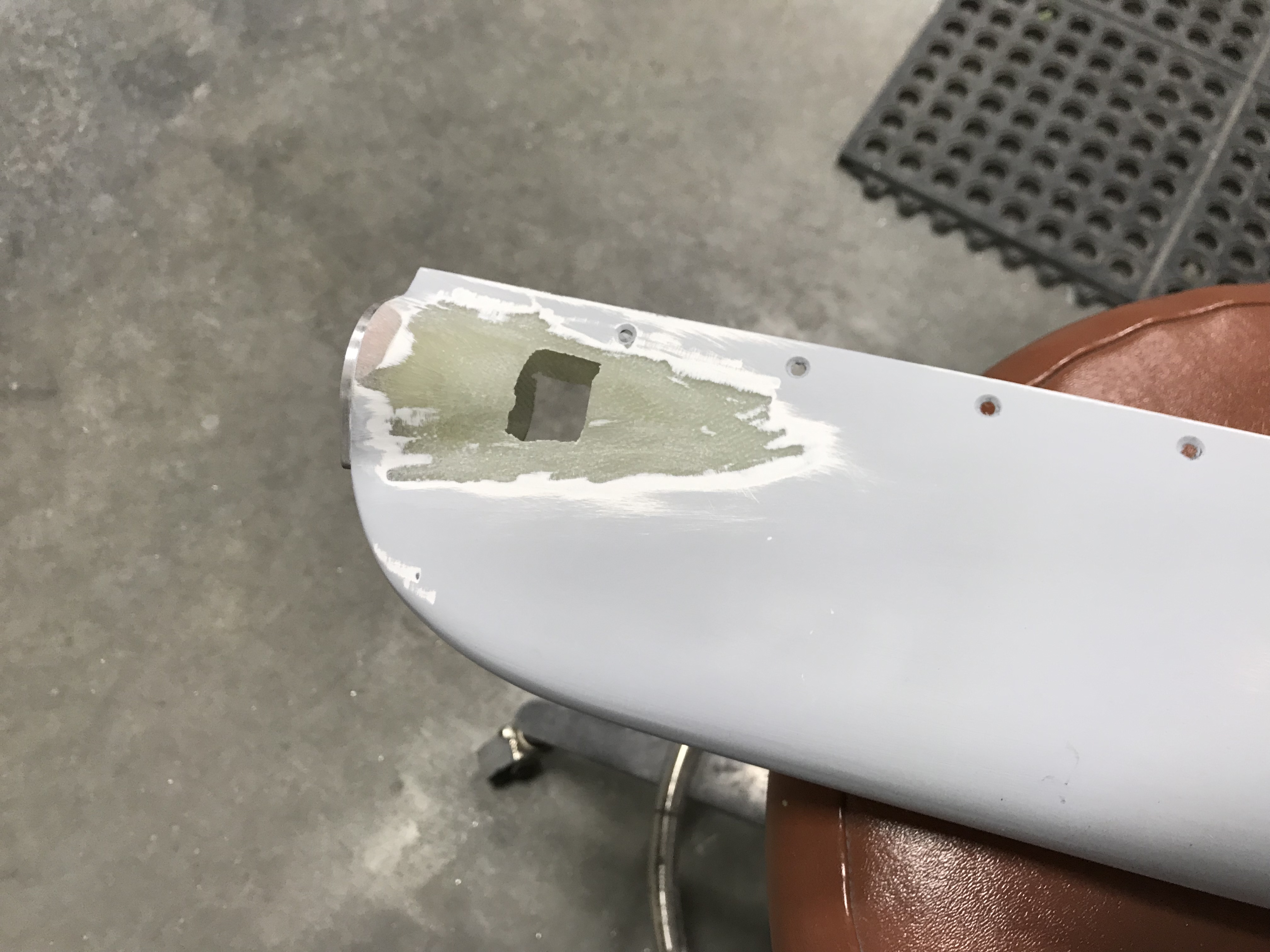
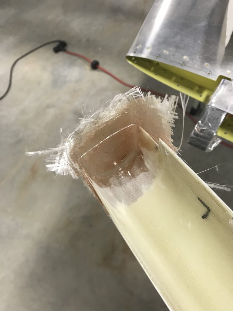
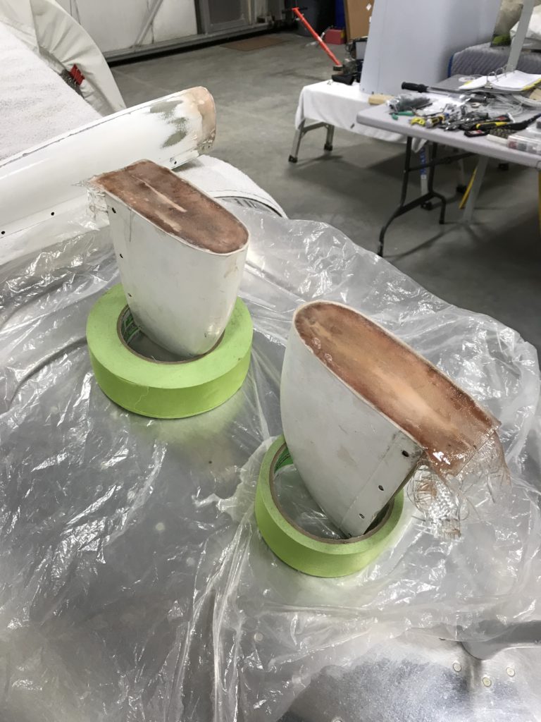
Here’s the inside of the tip after removal..it conformed pretty nicely but I had some voids in the cloth that required some additional epoxy to fill.

Interior of tip after removal

After sanding and before priming…looks good!

Finish-sanded tip

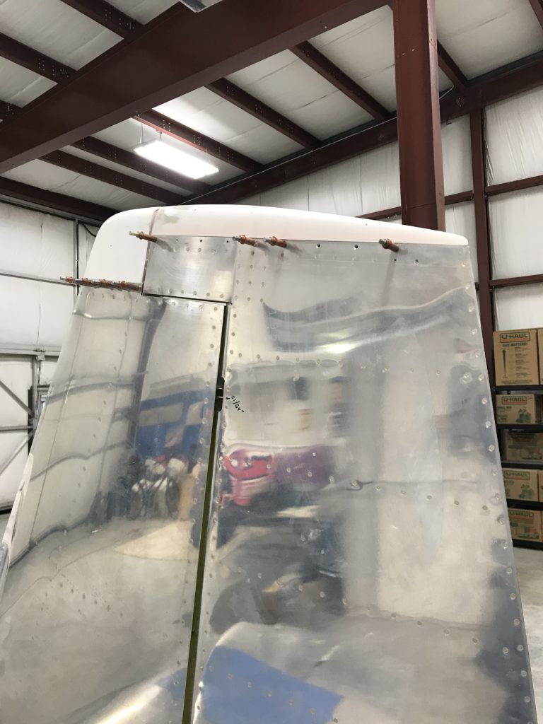
The HS tips come without a back end and there’s no requirement to add one but they look better and more “finished” if they’re closed – so that’s what I did, using the foam technique in Section 5 of the instructions and and a sheet of pink foam insulation from the aircraft construction department at Home Depot.

HS tips covered

The same foam closeout technique was used on the VS tip…already done in the pic below.

The rudder upper fairing was a really poor fit, a common complaint with previous versions of fiberglass parts shipped by Van’s. I had to build up the front end with balsa and fiberglass, and apply epoxy and microbaloons to fill gaps on either side.

Upper VS and rudder tips

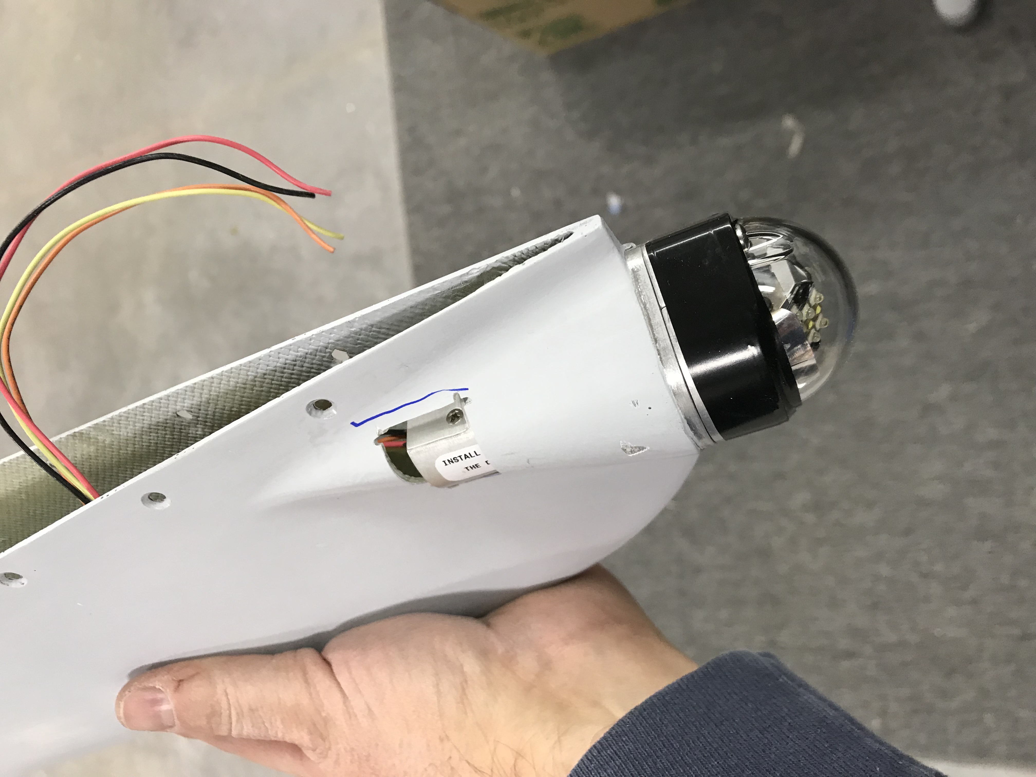
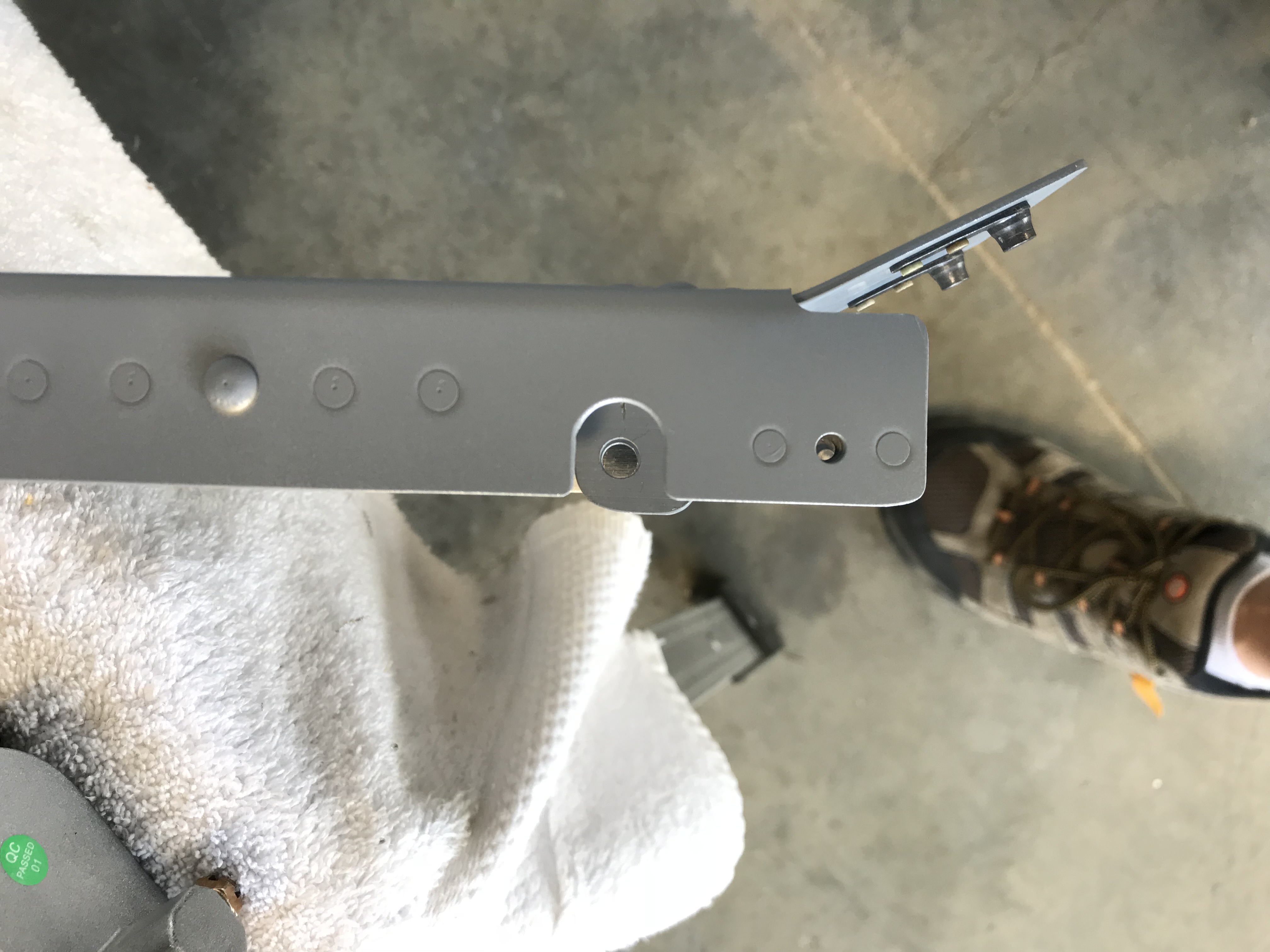
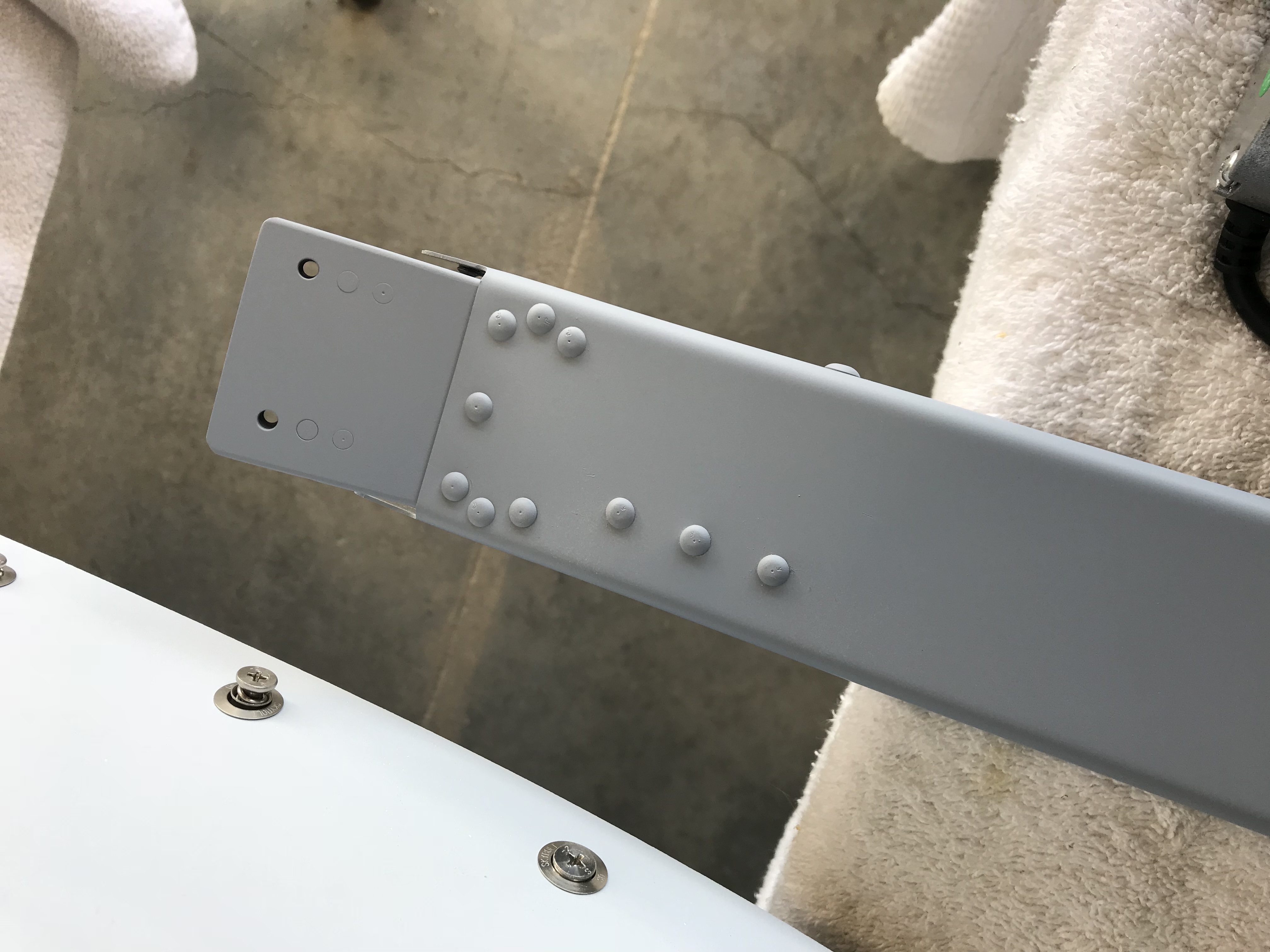
Surprisingly, the rudder lower end cap fit pretty well when trimmed to the scribe marks applied by Van’s. I decided to make it removable by adding #6 platenuts to fairing attach points on the rudder.

Lower rudder cap

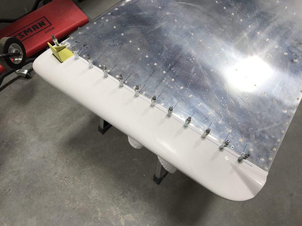
The lower end cap looks good now, but pop-riveting the nav/strobe light attach plate caused the fairing to crack (shit!) so I had to mix up some epoxy and flox for a fix.

Lower rudder tip fitted

Here are all the emp tips sealed and primed with K36 primer to protect them until time for paint.

"Finished" emp tips


Random tasks…

Finally getting a lot of little cleanup tasks done while the avionics harness is percolating at Approach FastStack.

First, I installed this…

Mystery device

First person to guess what it is gets a ThermosWorks sticker or a free beer at Oshkosh 2019.

Second, I dug out the cockpit lights from Oplite and fabricated a small bracket to mount them on the roll bar support.

Oplite 6sOplite wires

These lights are extremely well-made by my friend and fellow RV builder Rich Mileika. In addition to Oplite, Rich owns and operates Machine, Inc, a precision machining company in the greater Boston area. If you need quality cockpit lighting, try Oplite…you’ll like ’em.

And lastly, I replaced the stock Van’s flap motor with an upgraded version made by Pat Hatch at PH Aviation Services.

This motor has several advantages over the stock unit. The motor and jackscrew are separate so grease can’t migrate into the motor windings, a common problem with the Vans motor. It also has limit switches to stop the motor at full extension on either end, and also has a position sensor to report flap position to whatever device needs it.

The only downside is that the flap support bracket must be modified to accommodate the new motor. Rather than trying to rework the existing bracket, I bought new parts from Vans and started from scratch…only took a couple of hours, and Pat’s motor will save some wiring work later on.

Panel population progress

I think it’s time to start mounting stuff in the panel. Being an electronics/avionics geek, I’ve waited for this for a long, long time.

Panel population progressThe white labels are mockups of the panel labels I’m having engraved by Aircraft Engravers in Granby, CT.

The G3x GSU 25 ADAHRS is mounted on the subpanel behind the PFD/MFD – makes plumbing the pitot-static lines to the GSU and G5 a little easier. It was hard to get in there with a ruler to lay out hole positions so I made a drill template out of thin Al.

One minor hiccup…the ignition switch locking tab isn’t clocked correctly, causing interference between the switch body and panel support rib. I’ll probably have to grind off the tab and rivet on a new one at the right orientation. The switch label will cover the rivets nicely.

Switch interference

Mounting the avionics backup battery

More fun with avionics…finally figured out where to place the IBBS avionics backup battery, it’ll go behind the subpanel. The battery has a dsub connector on its right side, it’s placed so the connector will go though the subpanel lightening hole.

IBBS mountingTo make installation and removal easier I riveted nutplates to the battery’s mounting flanges.

IBBS nutplates

The light at the end of the tunnel…

…is getting brighter – it’s time to start installing and wiring avionics. I’ve been plotting and planning how to mount the Garmin G3x Touch system, radios and transponders and I’ve settled on building a tray which will hold all the remote-mounted LRUs, Comm 2 and transponder.

Here’s a cardboard mockup.

Avionics tray mockup…and the tray with avionics temporarily attached.

Avionics tray fitting 1The GAD 27 and GAD 29 are on the right side. Most of the airframe power interfaces will be through the right firewall passthrough so having these boxes on the right should make wiring a little more straightforward.

GAD 27 and GAD 29The GEA 24 engine interface is on the left side as most of the engine sensor wires will come through the left firewall passthrough. Guess where the AoA CPU is going?

GEA 24More pics? Sure, I’m glad you asked.

The avionics tray from overhead

Almost finished with the cowl

We don’t plan on painting the RV for awhile, so I called Jonathan McCormick at Evoke Aviation – our painter of choice – and asked for his recommendation about how to protect the cowl ’til time for paint. His recommendation was K36 high-build epoxy primer…so that’s what we used.

The K36'd cowl

The oil filler door looks good, although I’ll likely end up sanding down the sides a little to increase the gap for painting later on.

The oil filler doorAnd the cowl pin covers look great…couldn’t be happier with how they came out. They were worth all the work!

The jeweled cowl pinI disassembled the cowl and laid down some heat-reflective adhesive aluminum to help protect against hot spots from the engine.  Sorry, no pictures of that!