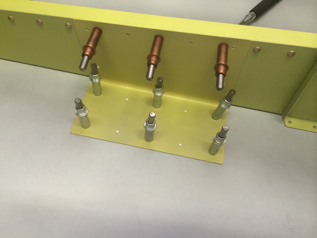
Tweaking the forward canopy frame
Framing the canopy
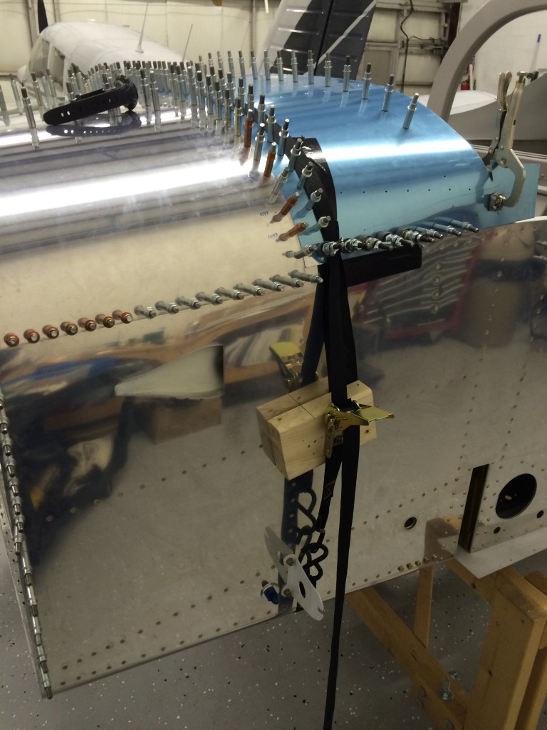
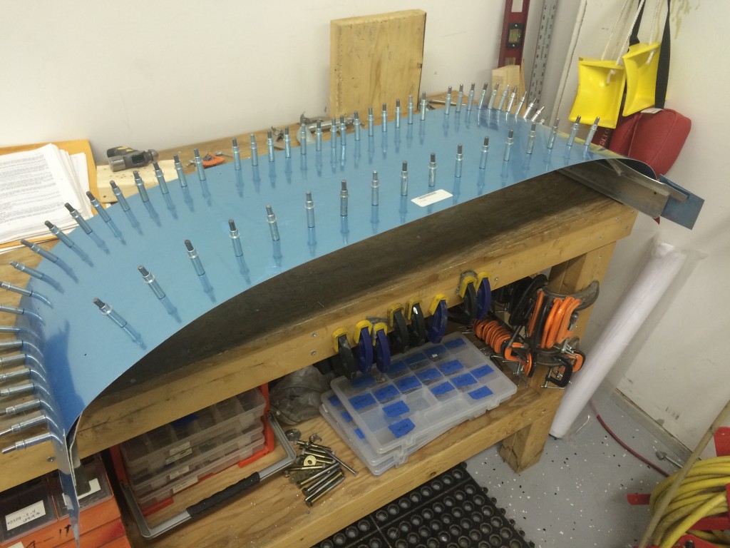
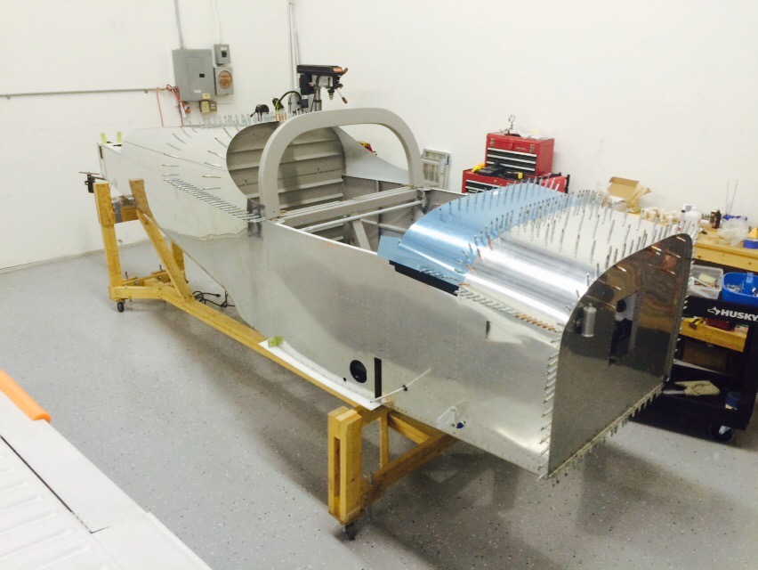
Today we started the last major structural part of the airplane – the canopy. The canopy is constructed from the forward edge back, and the first step is to fit the forward canopy skin to the welded aluminum canopy frame.
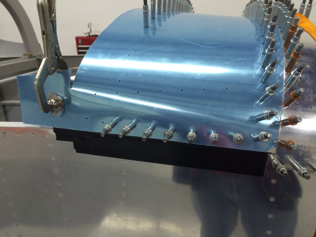
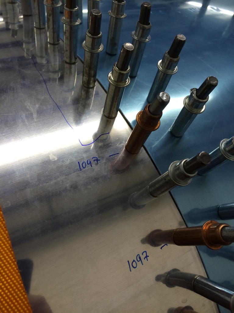
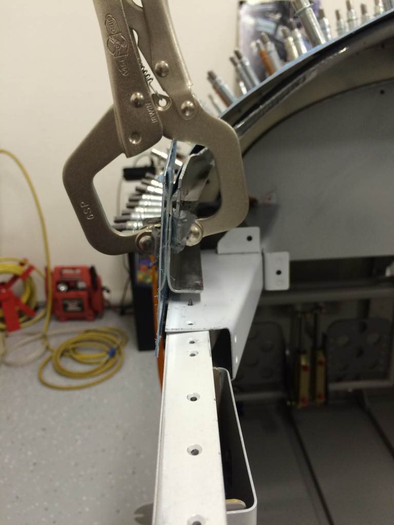
The frame has some holes already match-drilled in its forward ribs so it’s not tough to get the skin on the front of the frame, but the aft part of the frame is drilled in assembly with prepunched holes in the skin. The aft frame tube didn’t line up particularly well with the skin, so I had to apply some manual persuasion (i.e., I used a dead-blow hangar) to make the tube align with the skin for match-drilling.
I drilled the holes to #40, although they’ll be drilled later on to #30 and countersunk to accommodate blind flush rivets.
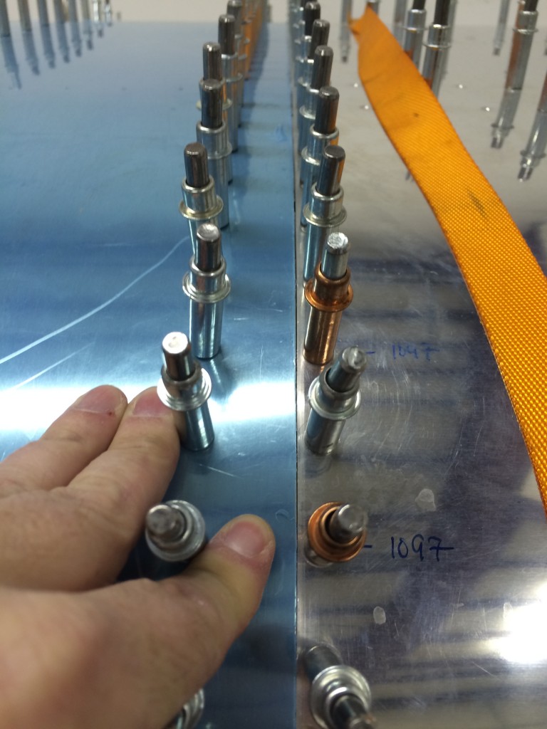
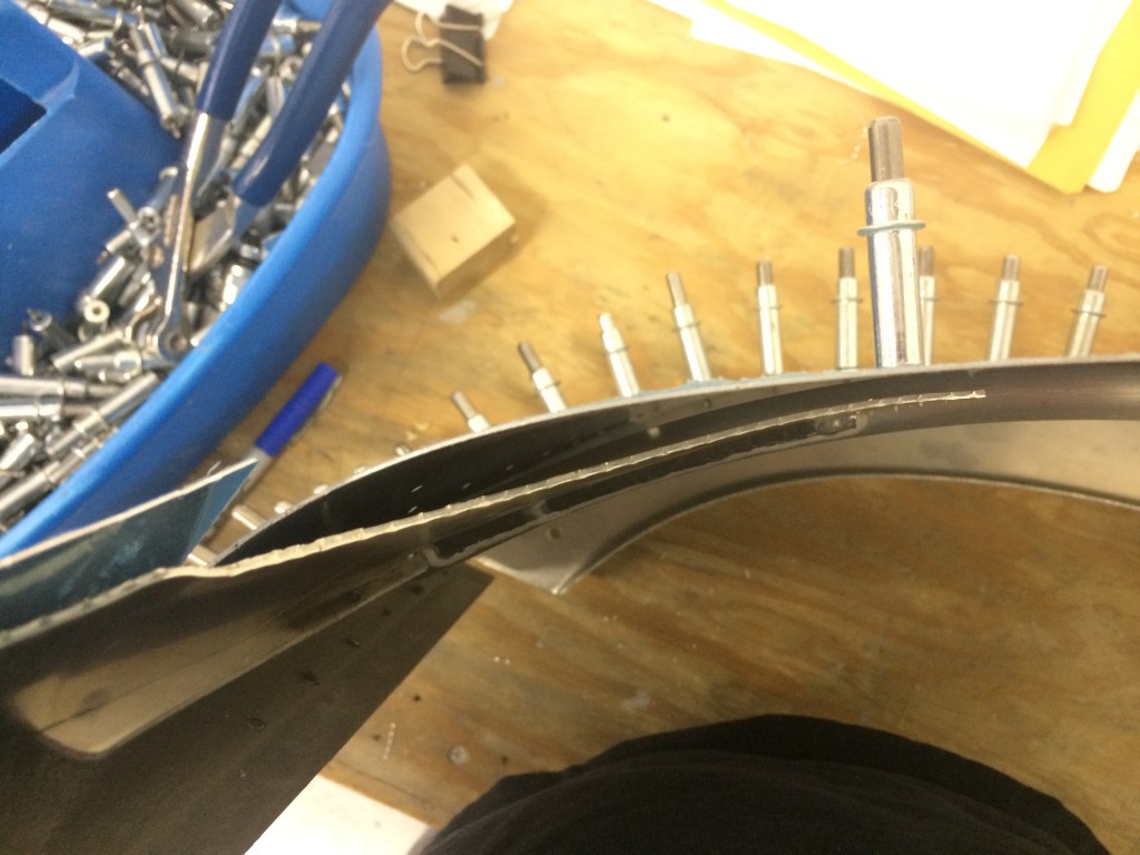
The skin still doesn’t fit particularly well…there are some gaps between the frame and skin that just can’t be closed. From reading various online forums and other builders’ websites, this is a common problem and I’ll find a way to deal with it.
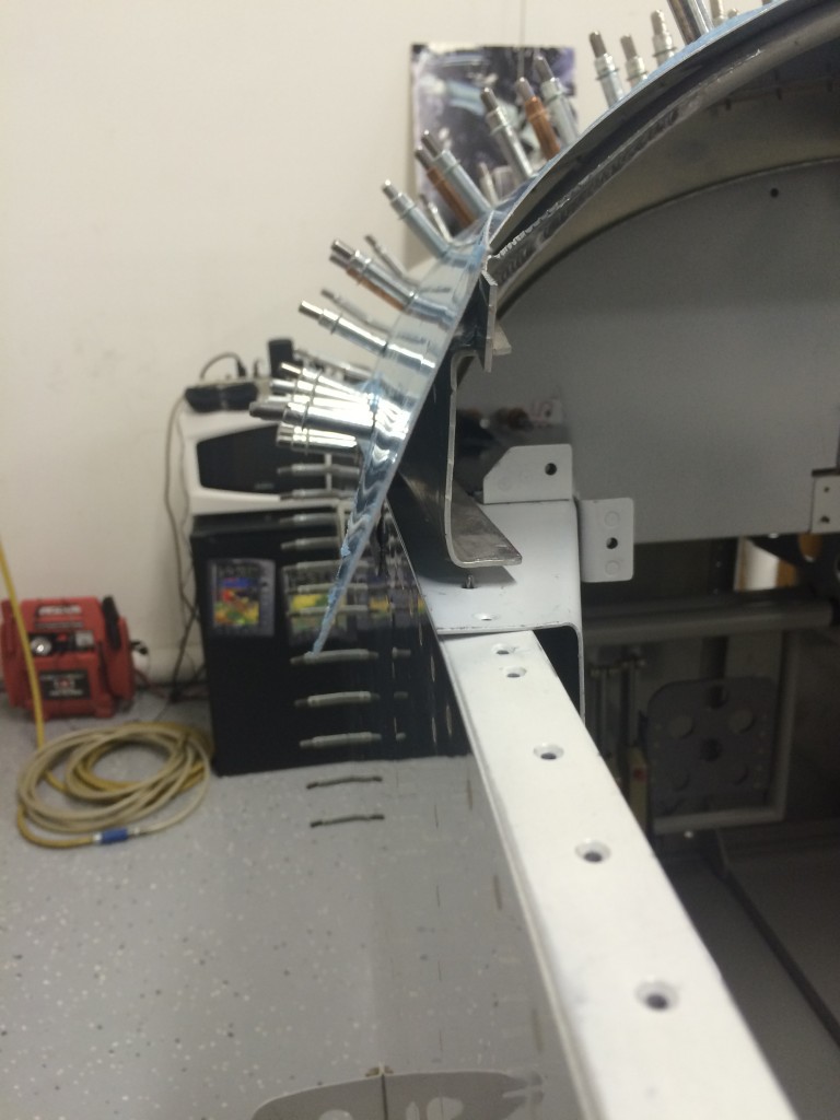 Also, the canopy frame sides don’t line up well with the fuselage. Some additional manual persuasion may be required here…
Pictures for Pat
Latches and linkages
Next up on the canopy task list…installing the side latch handle, linkage and latch tube. The only tedious part of this process was laying out and cutting holes – very visible holes – in the fuselage side skin to accommodate the latch handle slot and rivets.
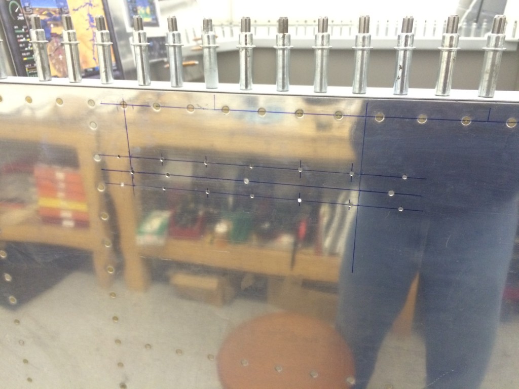
Vans includes a template in the plans to lay out and drill the holes, but I decided to measure and lay them out by hand. It took a little time, but the results were good.
The four larger holes in the middle mark the start and end of two rectangular holes for the canopy latch handle. I used – very carefully – a cutoff wheel in my Dremel tool to start the holes, then finished them with a flat jeweler’s file.
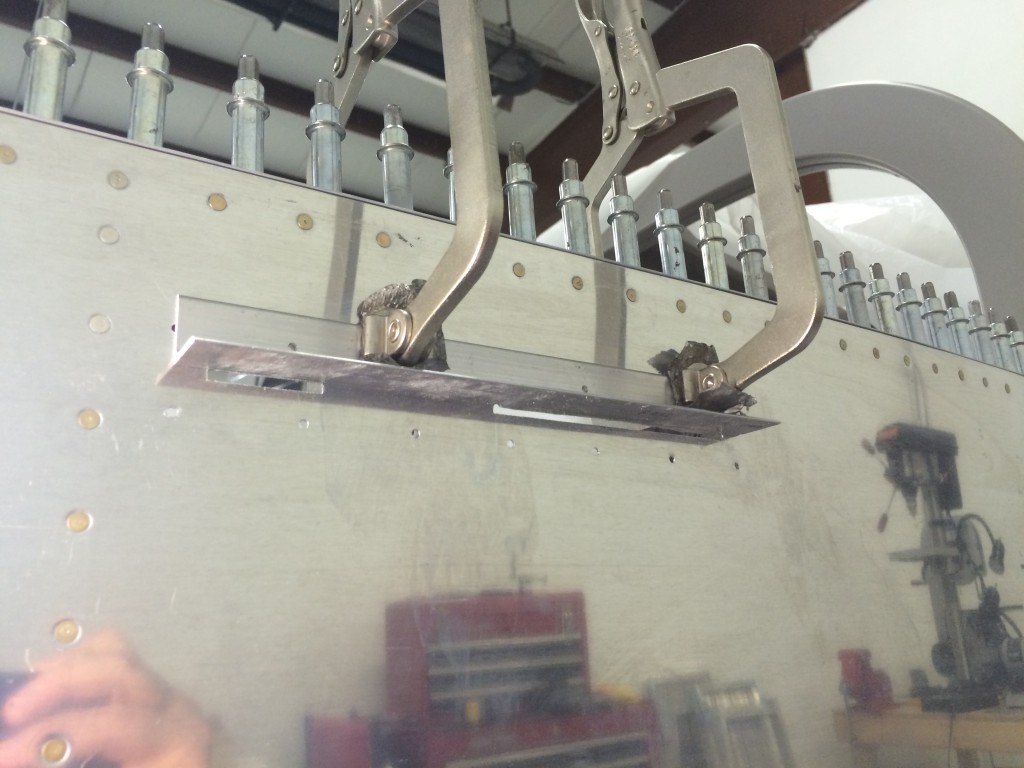
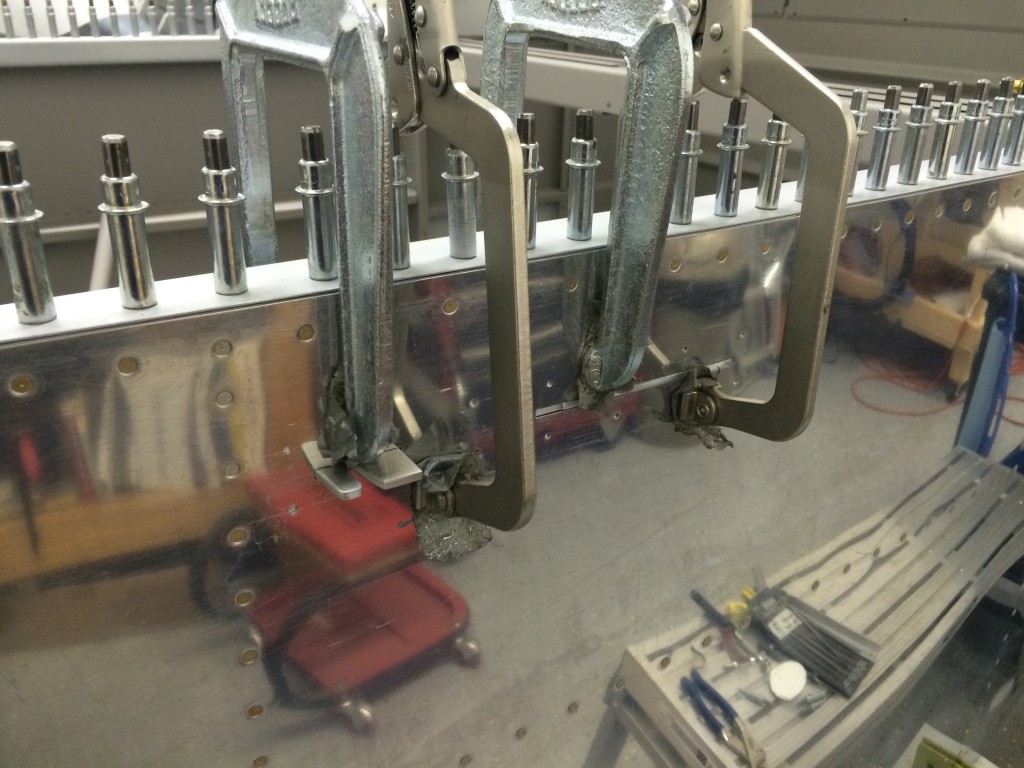
I borrowed an idea from fellow builder Mike Bullock and clamped a piece of scrap angle to the skin as a reference for filing. The holes came out nice and straight…very cool.
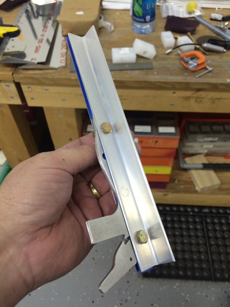
Here’s the latch mechanism itself – two pieces of 0.063″ angle sandwiching the latch handle (top) and locking mechanism (bottom).
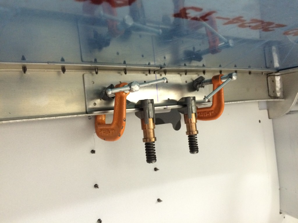
The latch mechanism fit almost perfectly in the slots I cut – only a little adjusting was required on the front hole. I clamped the mechanism in place and match-drilled the angles to lock the whole assembly into place.
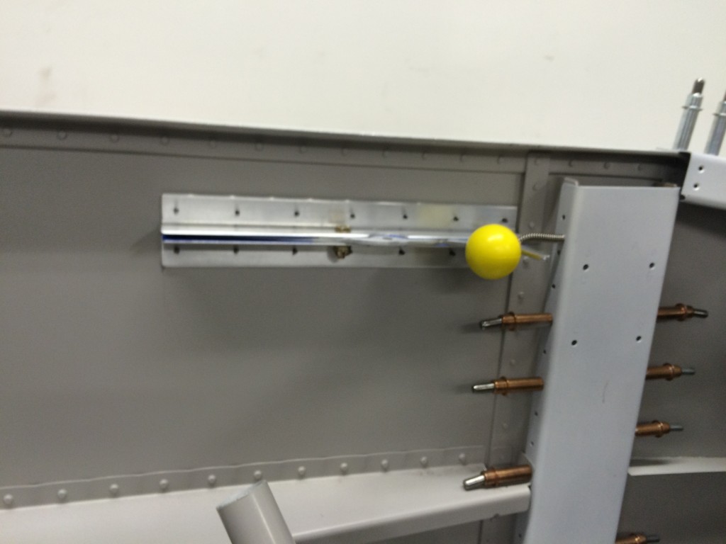
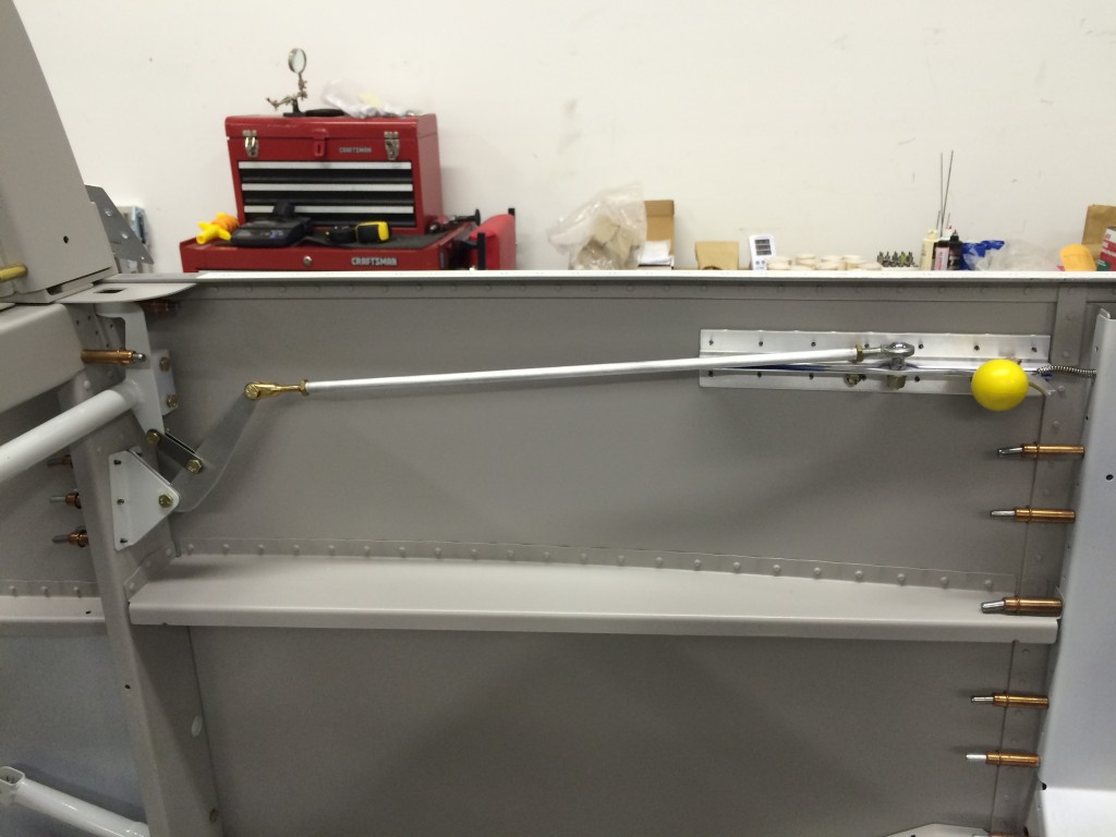
Here’s the other side with the spiffy yellow latch knob installed. There’s also a very small hole drilled in the wing carrythrough bulkhead which supports a small spring that keeps the locking mechanism pressed against the latch handle.
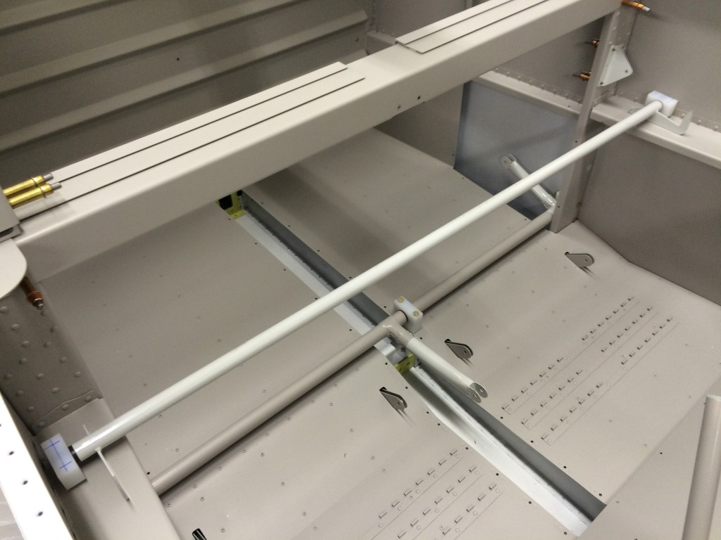
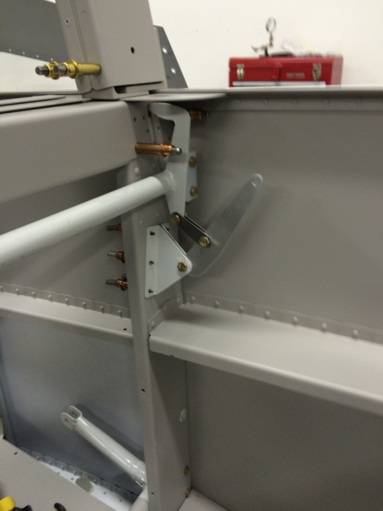
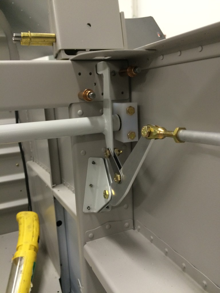
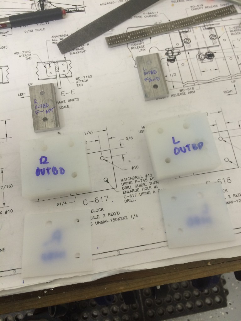
The latch tube itself is held in place by two Delrin blocks that are match-drilled to the F-705 bulkhead. Fingers on the latch tube engage holes in the bulkhead. There was only one minor problem – the tube was slightly too long, which made it impossible to center the blocks on the F-705 reference holes. A tubing cutter took care of that problem.
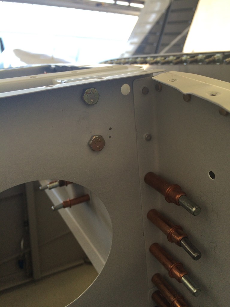
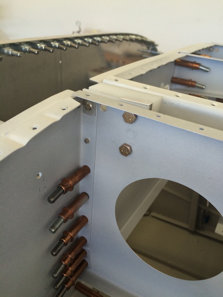
I drilled the blocks to #10, and the F-705 holes to #12, to accommodate AN3 bolts that hold the blocks to the bulkhead. Here’s the tube bolted into place, and two parts of the latch linkage in place.
The only remaining part to be fabricated was the pushrod that connects the latch handle to the latch tube linkage. Nothing too difficult, just a lot of twisting with a 1/4″-28 tap.
And here’s the final product…everything works smoothly. Cool.
Finishing the elevator pushrods
Starting the canopy
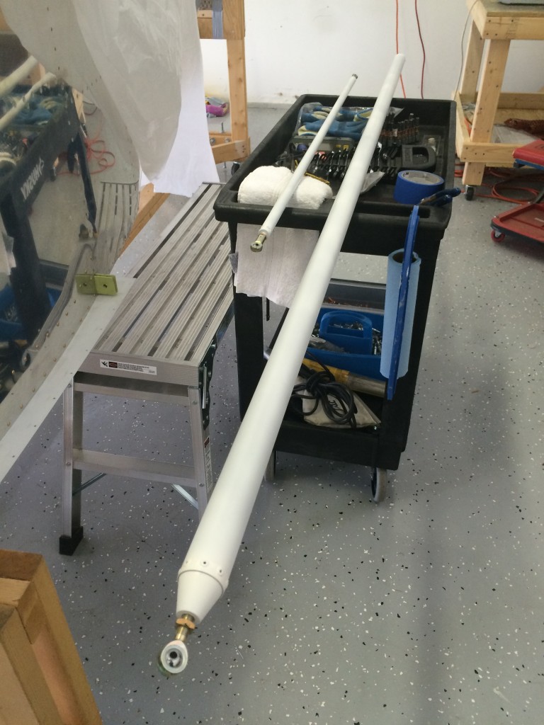
Although I still have to finish up the elevator pushrods and mount the horizontal and vertical stabilizers, I’m moving on to the canopy frame while I decide what to do about Van’s horizontal stabilizer service bulletin. I haven’t decided yet whether to mod my horizontal stabilizer per the bulletin, or just build a new one…
First steps on the canopy are fabricating the alumunum and Delrin spacers that accommodate the canopy hinges. Nothing too complicated here…
Fitting them to the forward subpanel was slightly tricky, since Vans tells you to predrill holes in the spacers that they tell you later to match-drill in place with the subpanel. Fortunately, the hole locations called out in the plans are spot on, so I didn’t have much trouble fitting the spacers.
I didn’t take any pictures of the fitting process, but here’s the finished product on the left side…
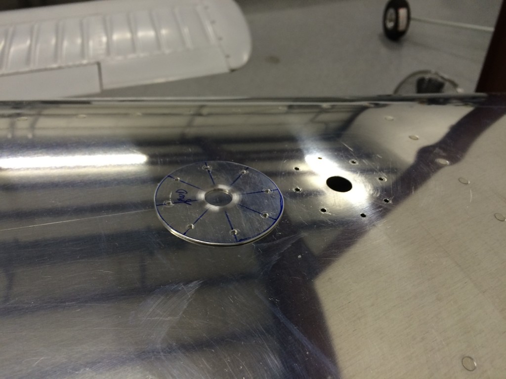
Installing the ELT antenna doubler
Random stuff
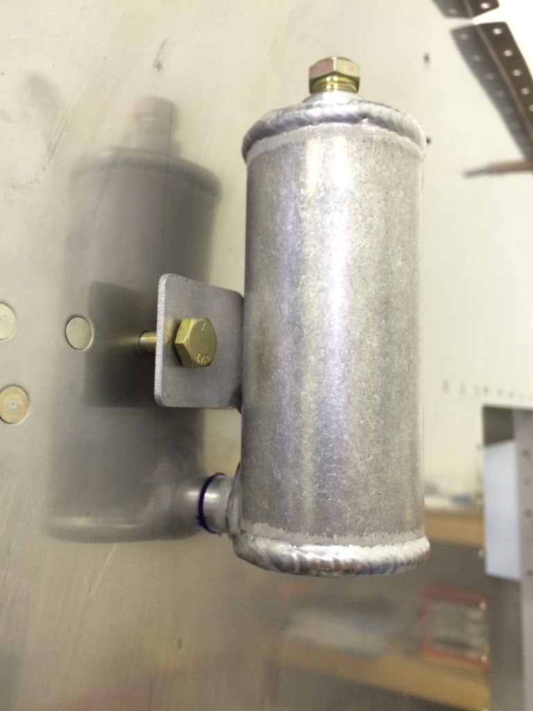
I’ve been taking care of a lot of random stuff on the fuselage before starting on the canopy. First up was mounting the brake reservoir..not too difficult except for figuring out how to accommodate the brake connection on the aft bottom. I traced a hole around it, then used a Unibit to open the hole. After everything was drilled and ready for mounting, I laid a bead of firewall sealant around the connection where it penetrates the firewall.
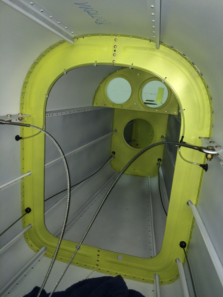
I also installed static lines in the aft fuselage. I was able to do this without crawling into the tailcone, but it was a lot of work. The static lines are held in place by RTV – this is what Vans’s instructions call for so I hope it works. I also ran the static line forward through the clips I installed when riveting the aft turtledeck skin.
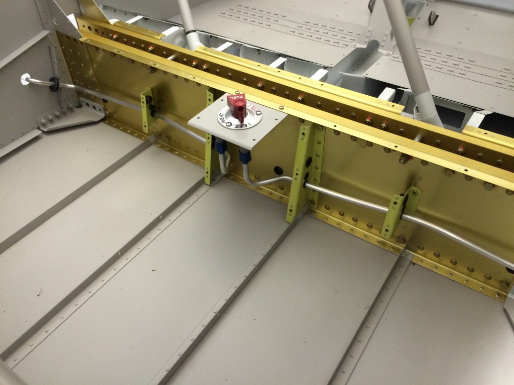
I also ran fuel lines from the fuel selector to the fuselage sides. Once again, I kinda screwed up here – this should have been done while the wings were temporarily installed. Not a big deal, though – they can be tweaked when the wings are permanently installed.
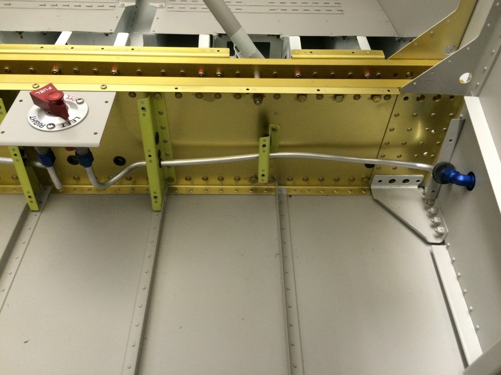
Here’s the fuselage left side that gets routed to left fuel tank’s inverted pickup. Some builders have managed to do one continuous line from the selector to the tank, but I didn’t want to waste a lot of tubing figuring out how to do that so I’m installing an elbow fitting on the fuselage skin. There will be another line that routes to the tank from this fitting.

