It’s been a couple of weeks since I posted any progress on the fuselage. Doesn’t mean I haven’t been working, I’ve just been too busy to update the website. Here’s a quick collection of everything I’ve done recently.
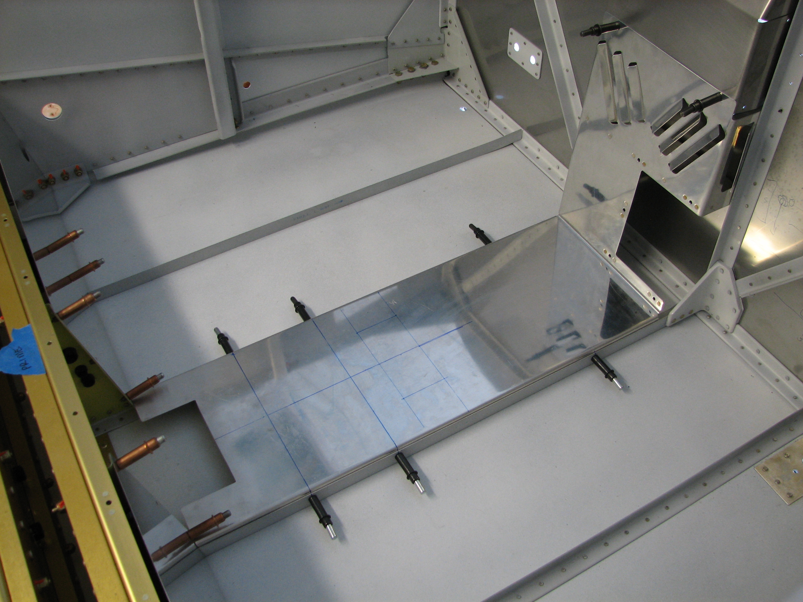
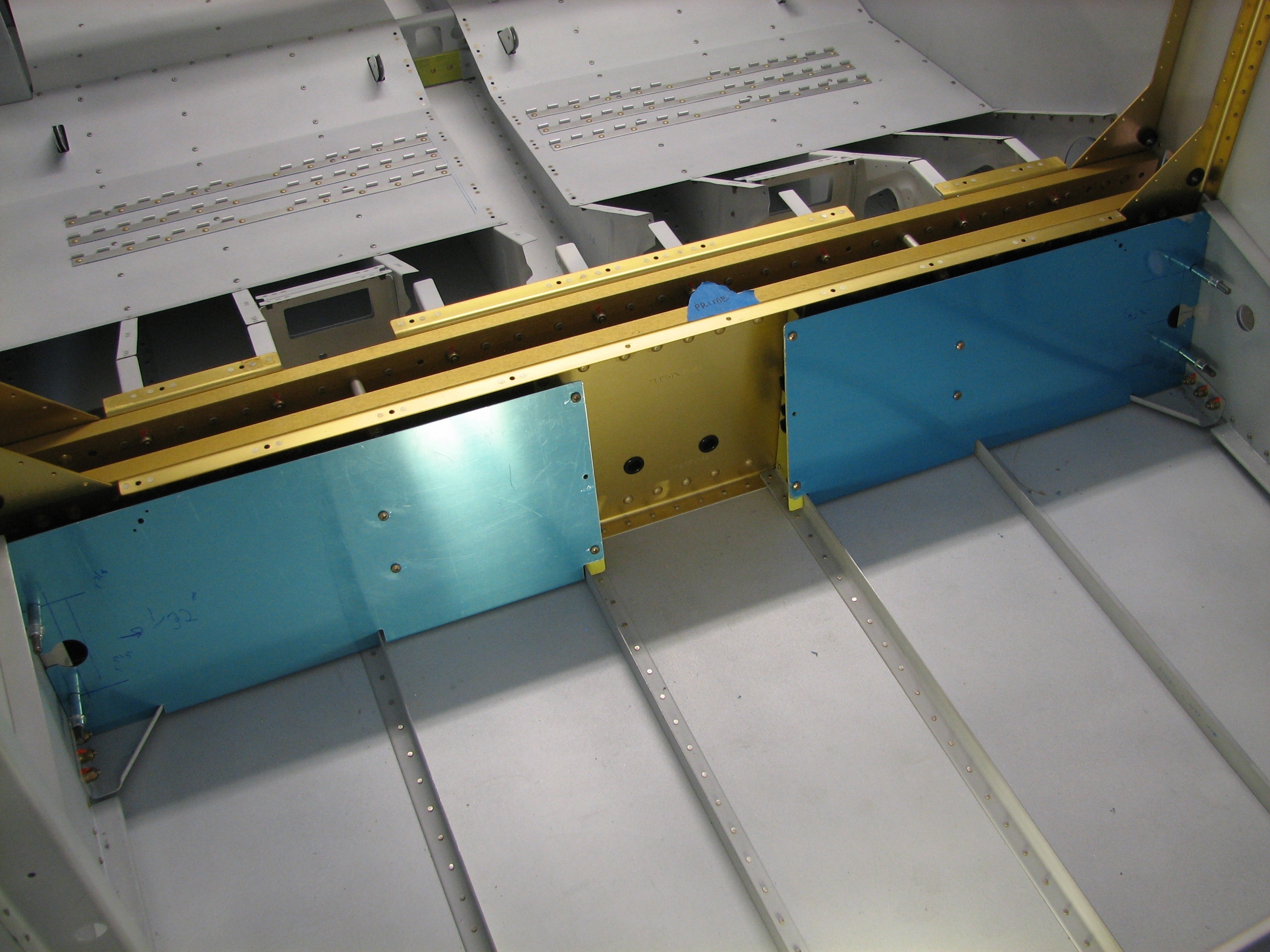
Once I knew I could connect the fuel pump to the fuel selector, I positioned and drilled the forward tunnel cover to the center floor stiffeners. The plans only call for two fasteners on each side, but I added another to accommodate some reinforcements for the fuel pump support structure (more on that below).

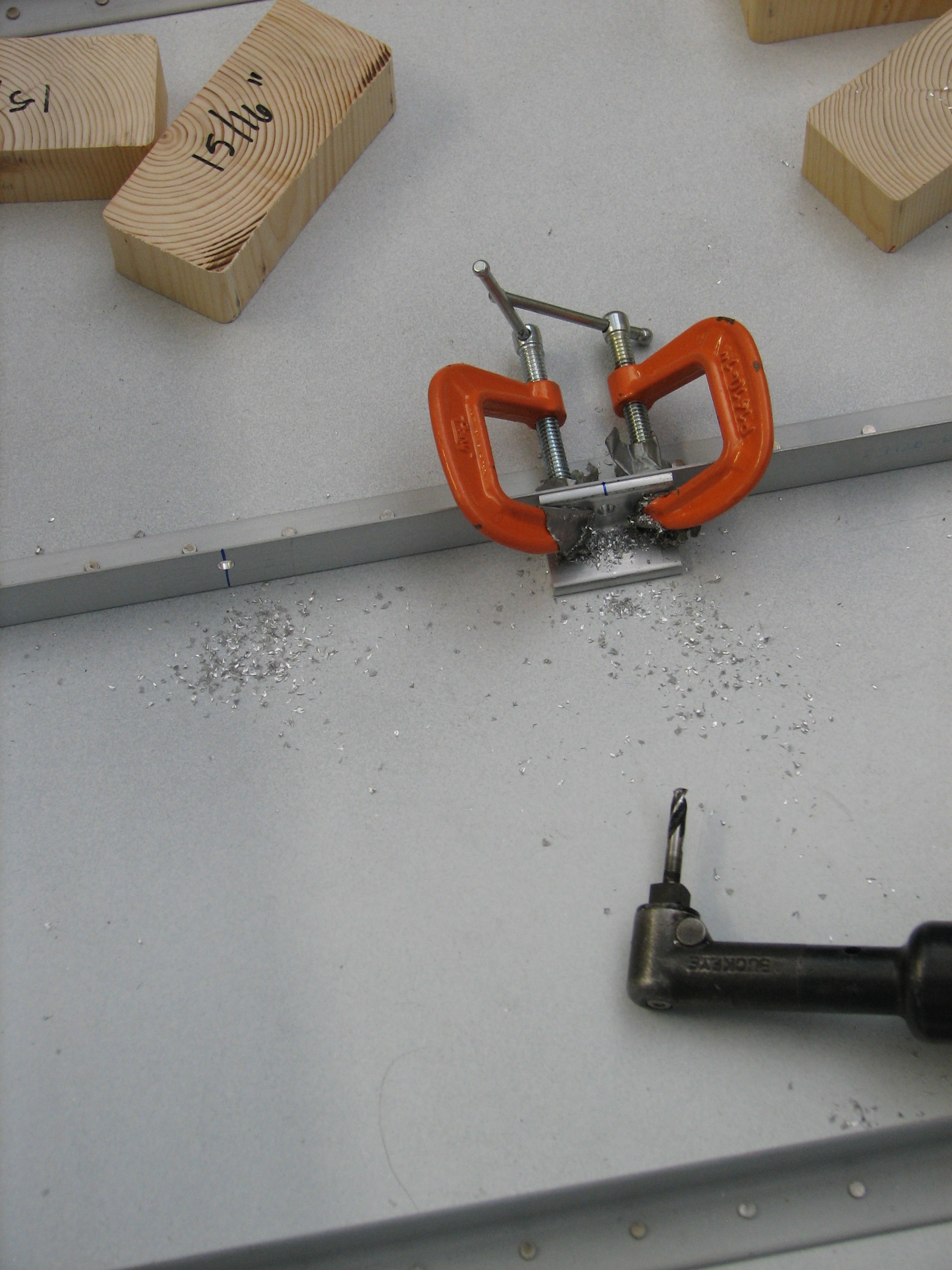
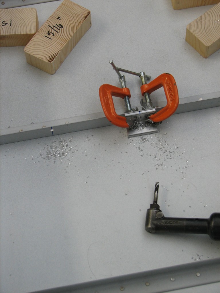
The’s nothing particularly difficult about drilling these holes, except that the bottom surface of the cover needs to be 15/16″ above the floor. Some spacers made from scrap 2″x4″ made that relatively easy. I also used a bit of scrap 1/8″ aluminum angle as a drill jig to make sure the holes were drilled at the right height above the floor..big thanks to Mike Bullock for that idea. And for me at least, angle drills are hard to position precisely…the drill jig helped with that as well.
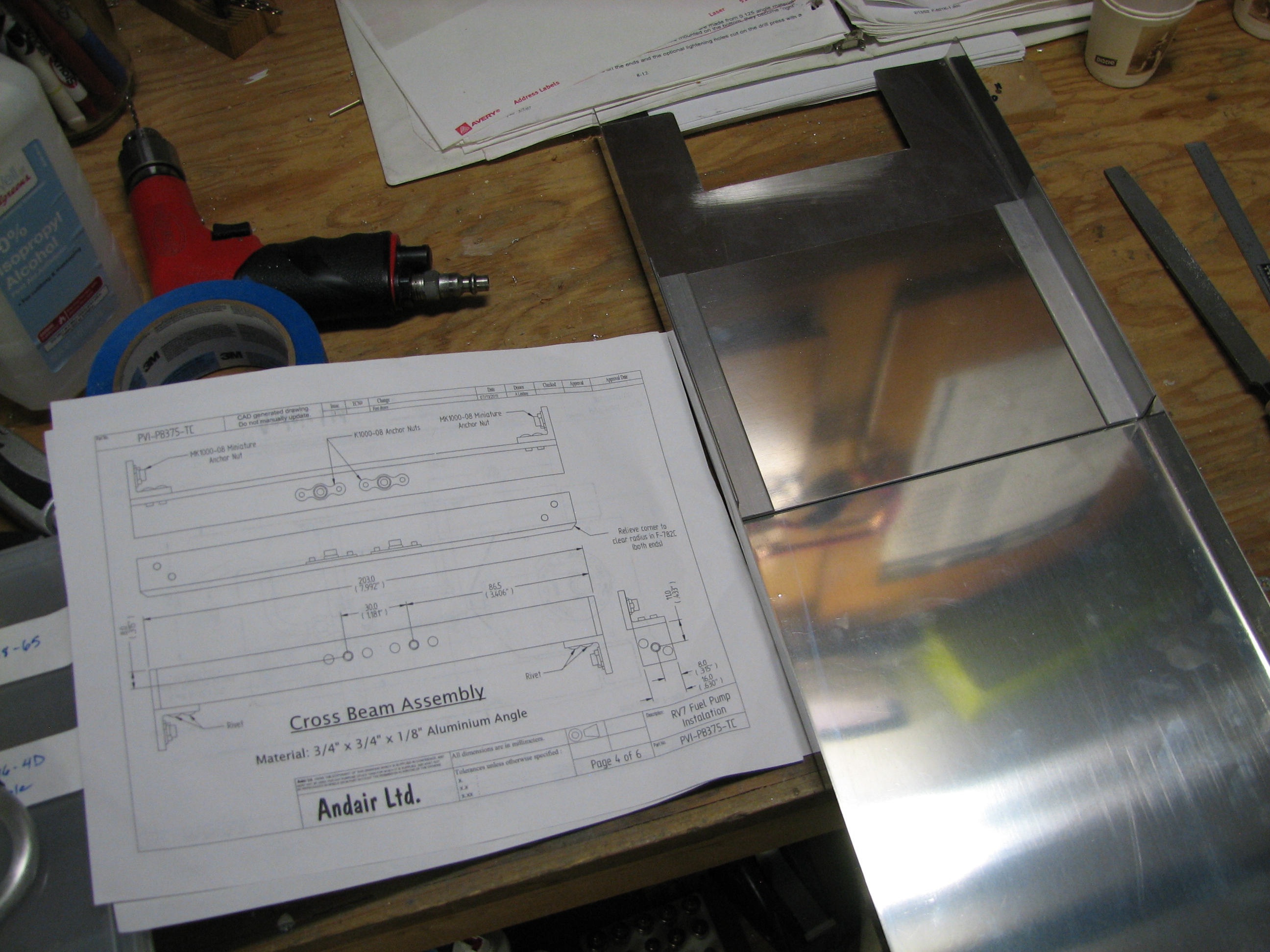
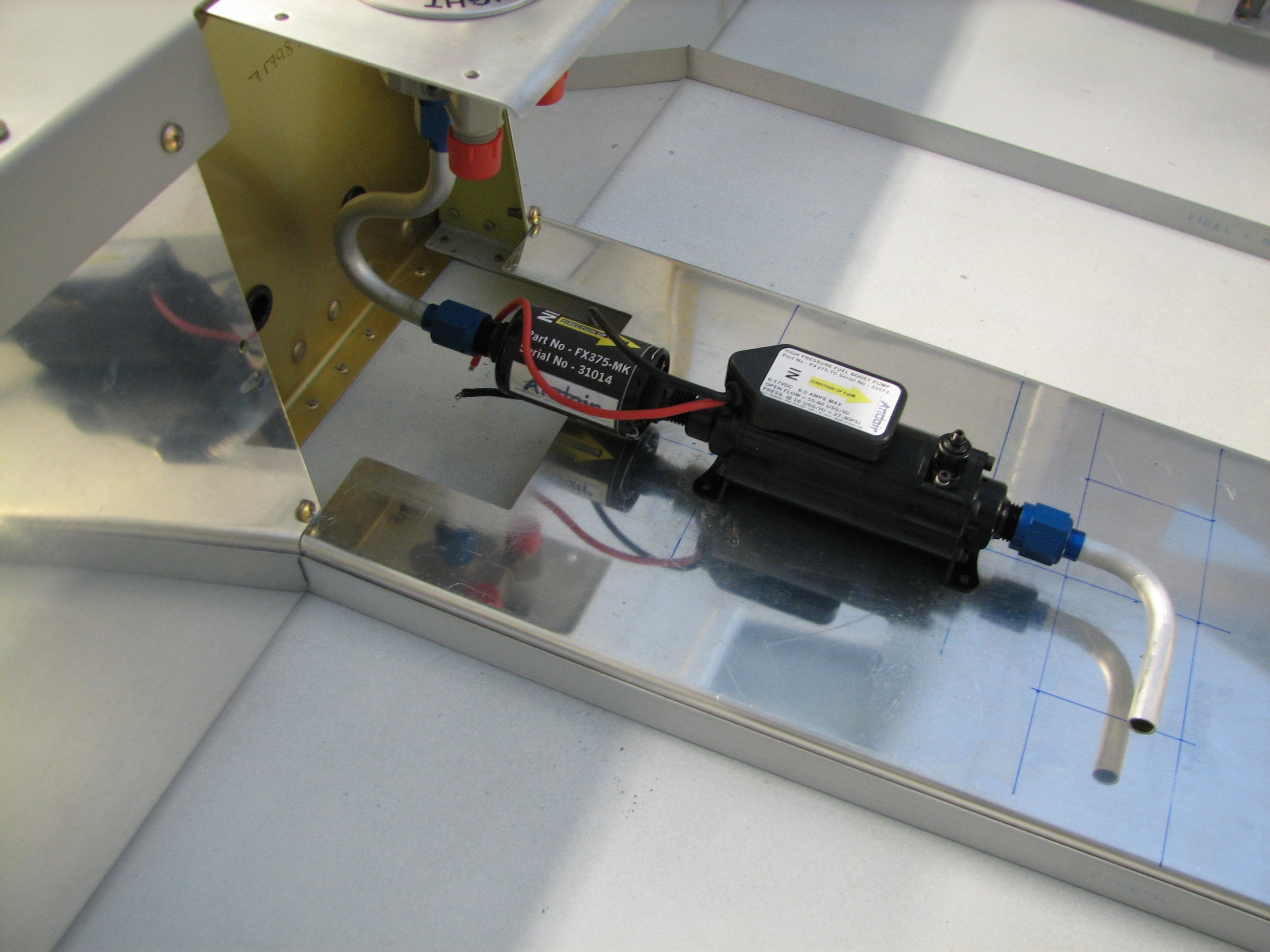
Andair publishes a really nice set of plans for a reinforcement structure to support their fuel pump and filter on the forward tunnel. Problem is, their heavy 1/8″ support angles completely block off area under the tunnel, and make it impossible to run wiring through that area – and they’re complete overkill structurally for a pump that barely weighs a pound.
 After doing some research online, I found other builders were using 0.63″ angle and plate to reinforce the pump mounting area. And since Van’s mounting bracket for the Airflow Performance pump and filter is made from a similar gauge of aluminum, I decided to go with the reinforcement plate and angles.
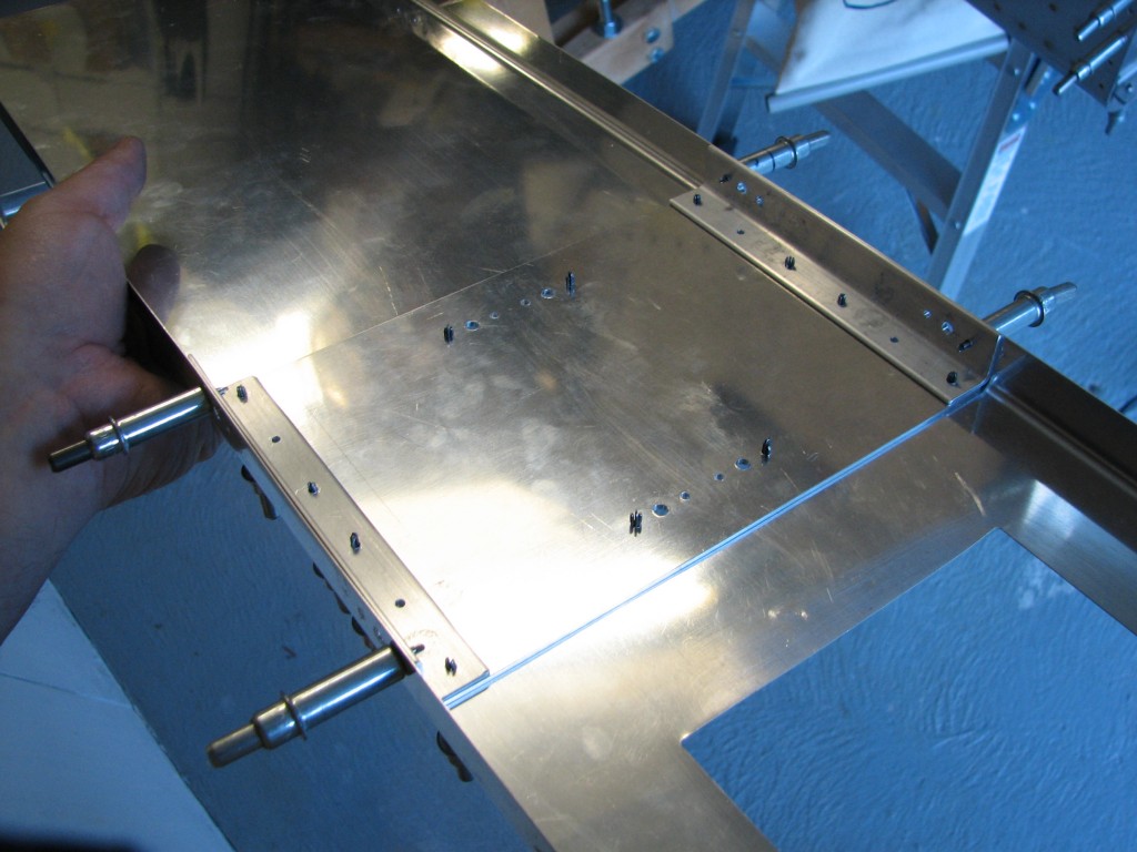
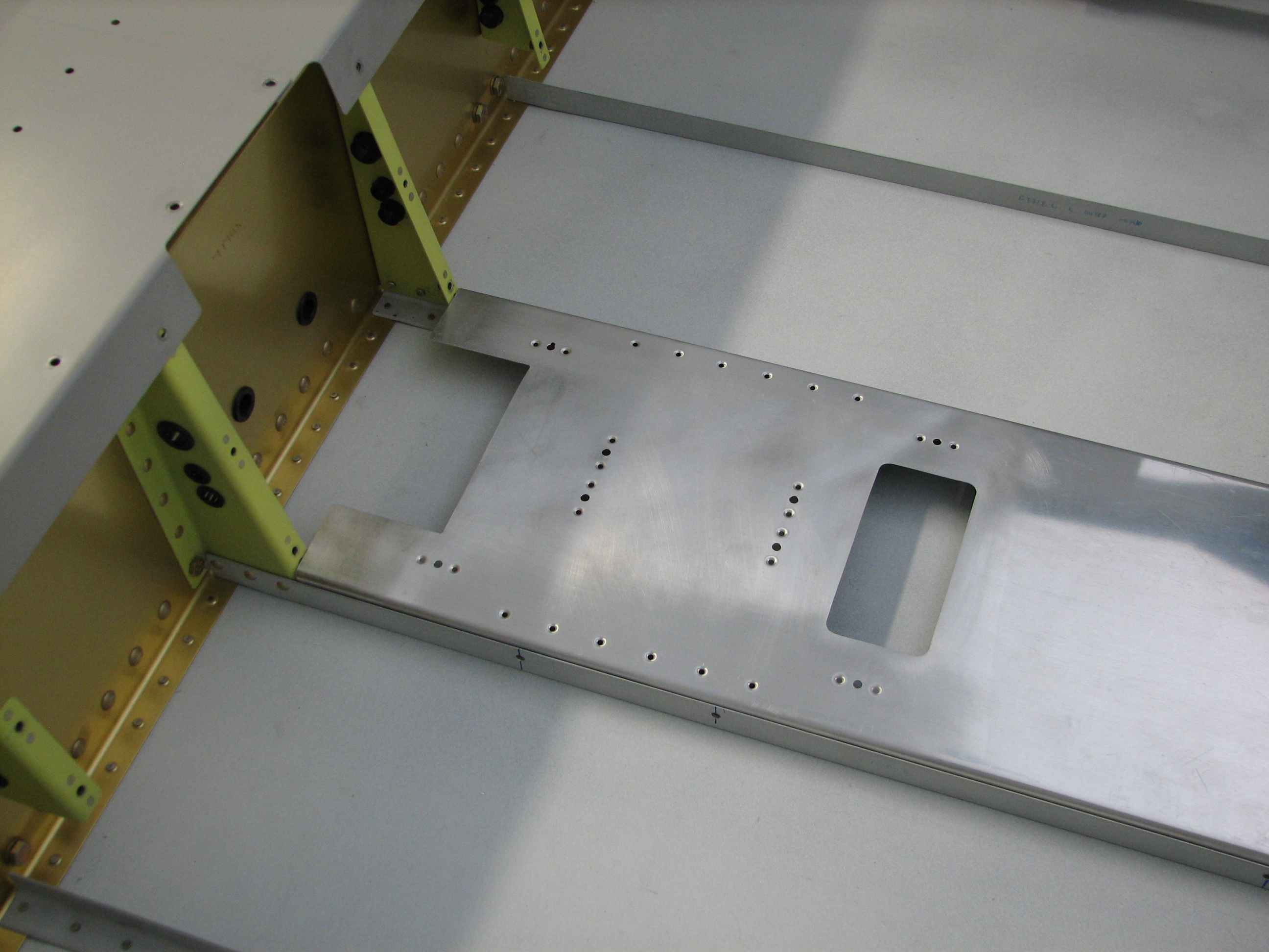
Here’s the plate and angles match-drilled to the bottom of the tunnel cover. I’m very happy with the way this turned out.

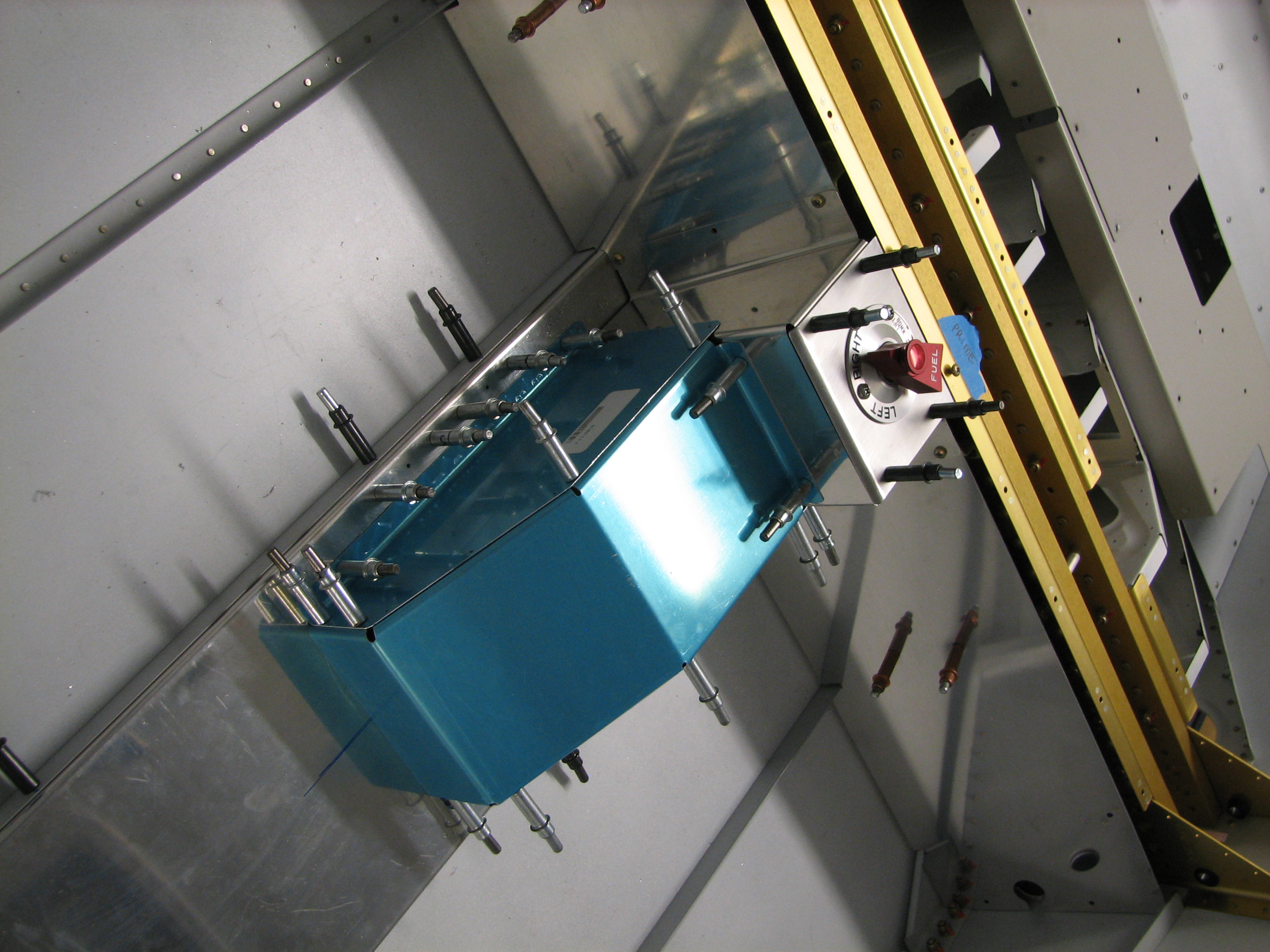
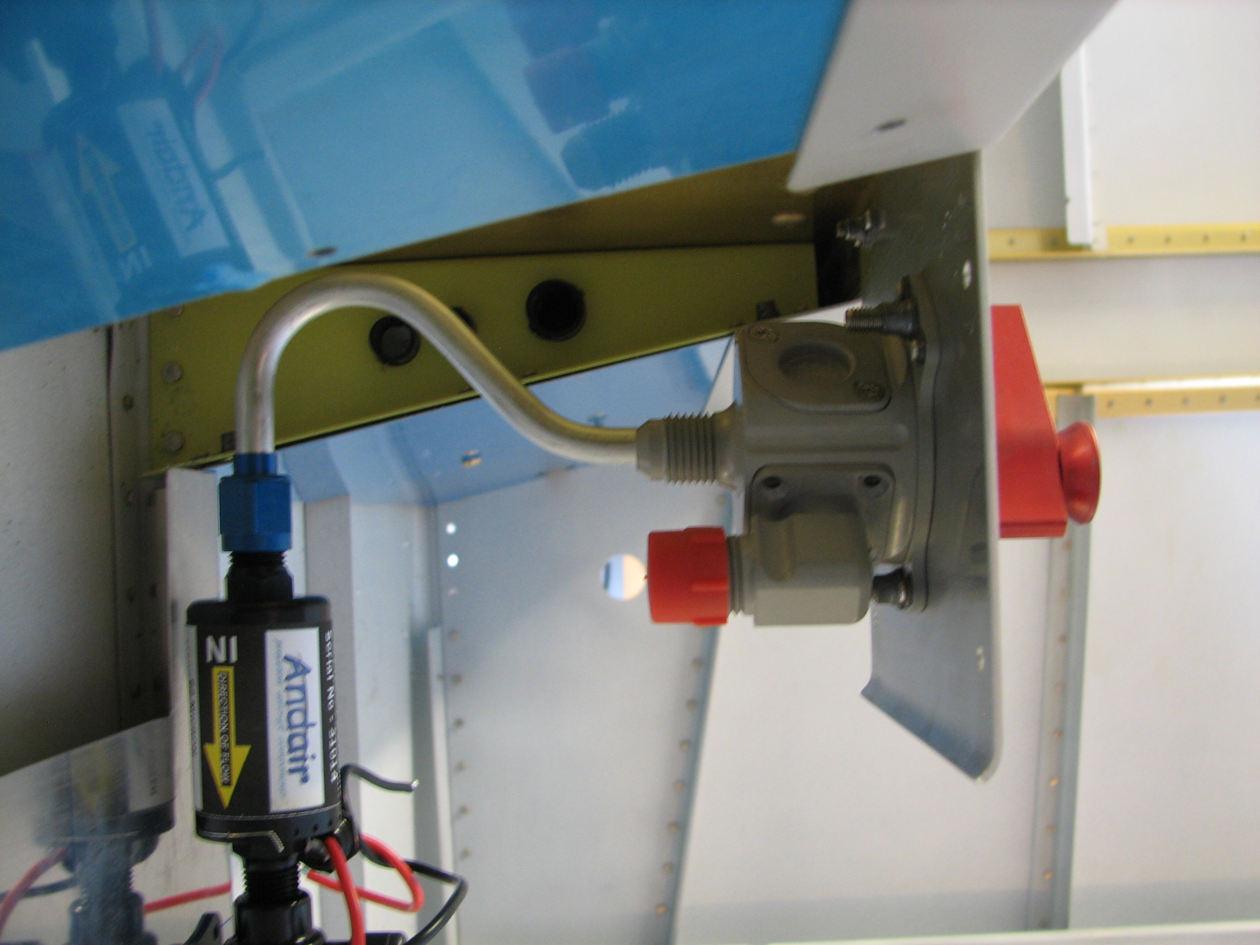
Knowing that the pump and filter were in a good location, and with the mounting holes drilled, I opened up a rectangular area ahead of the pump per Andair’s plans, to allow the fuel line to route under the tunnel cover to the firewall.
 The only thing left to do in this area was to match-drill the pump cover to the tunnel and fuel valve cover. Nothing too difficult here, just need to make sure the pump cover flanges are positioned neatly along the tunnel sides.
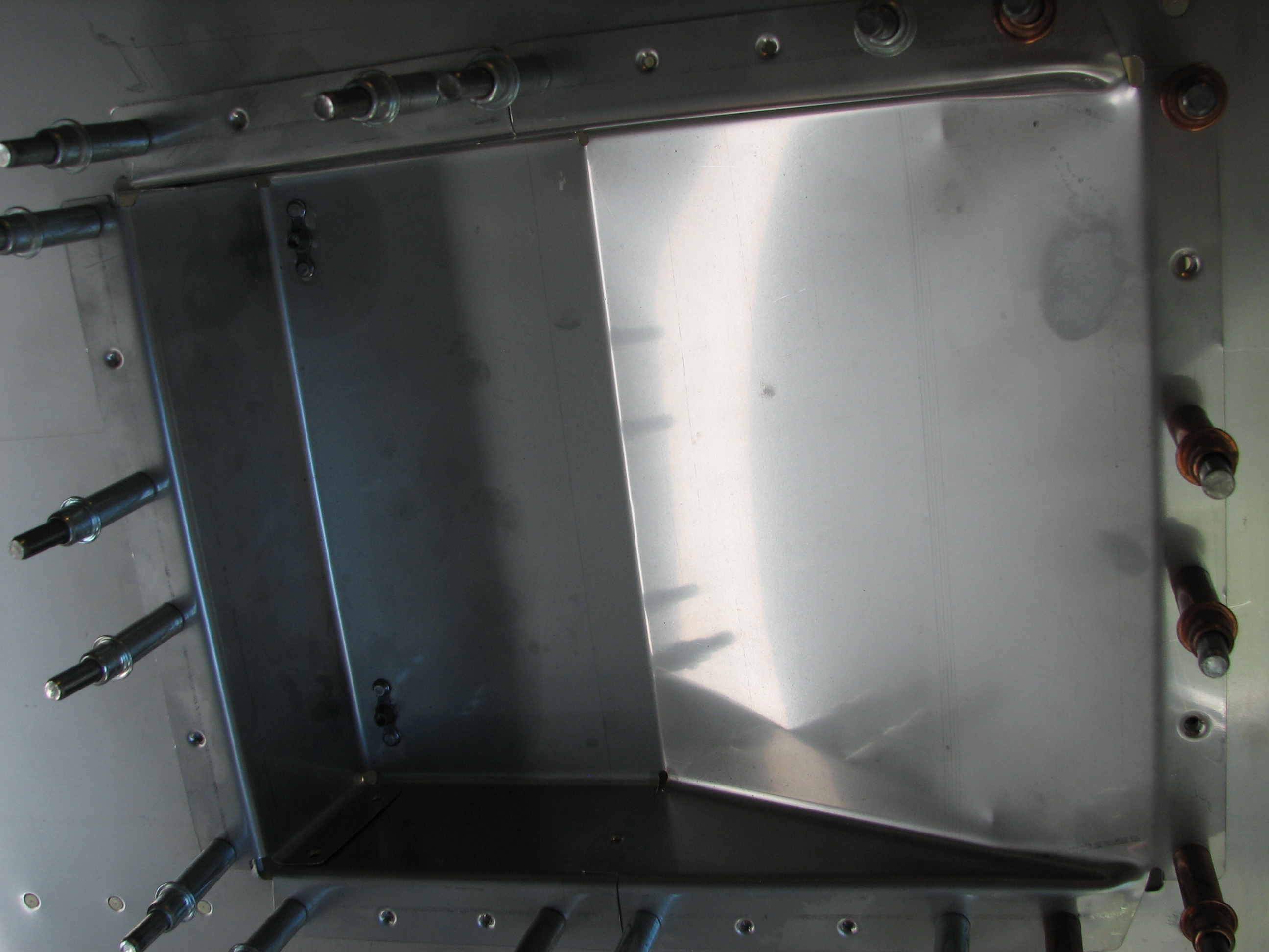
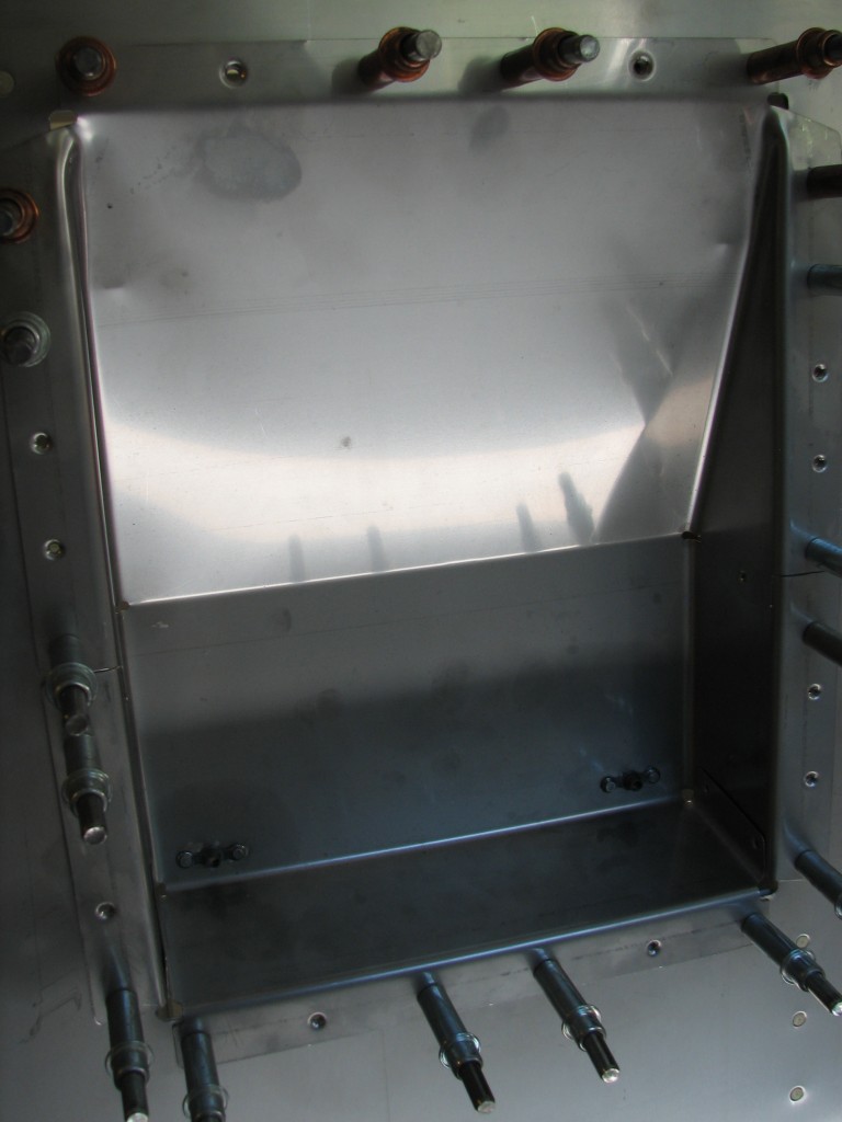 There’s a portion of the tunnel cover that acts as a heater plenum, and it’s attached to the firewall oil filter cutout with #8 screws and platenuts. I’d forgotten what a pain in the ass it is to drill stainless steel…the screw holes aren’t beautiful, but they’re functional.
The final bit of work to do in the forward fuse was mounting the flap actuator, motor and support structure.
 I haven’t touched this weldment and supports in a couple of years, when I match-drilled the UHMW supports to the seat back bulkhead. One less part in the pile…
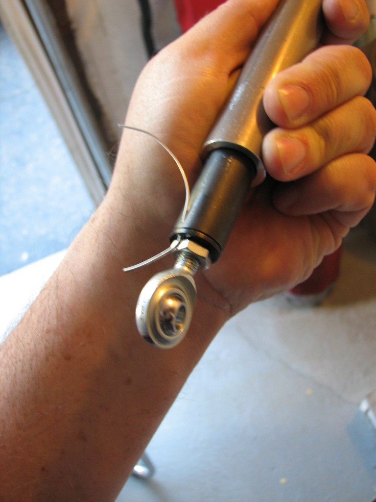
Van’s issued a service bulletin several years ago requesting that builders safety-wire the flap motor rod end to make sure it doesn’t unscrew itself, thus making the flaps inoperative. Per instructions, I drilled a hole for the safety wire. I was afraid this would turn into an expensive mess, but the center punch and a #50 drill bit made quick work of it. I know, the picture is fuzzy…sorry.
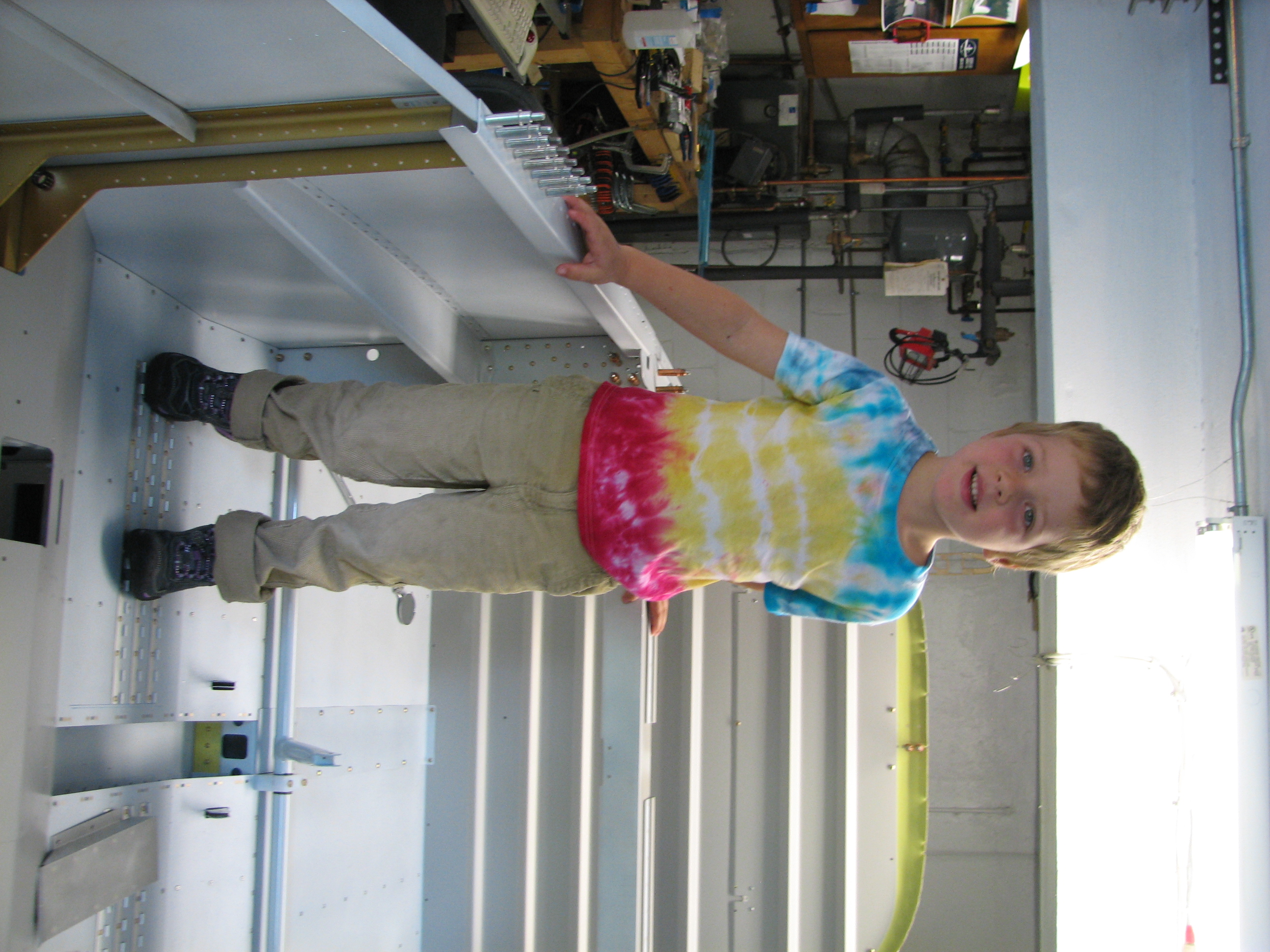
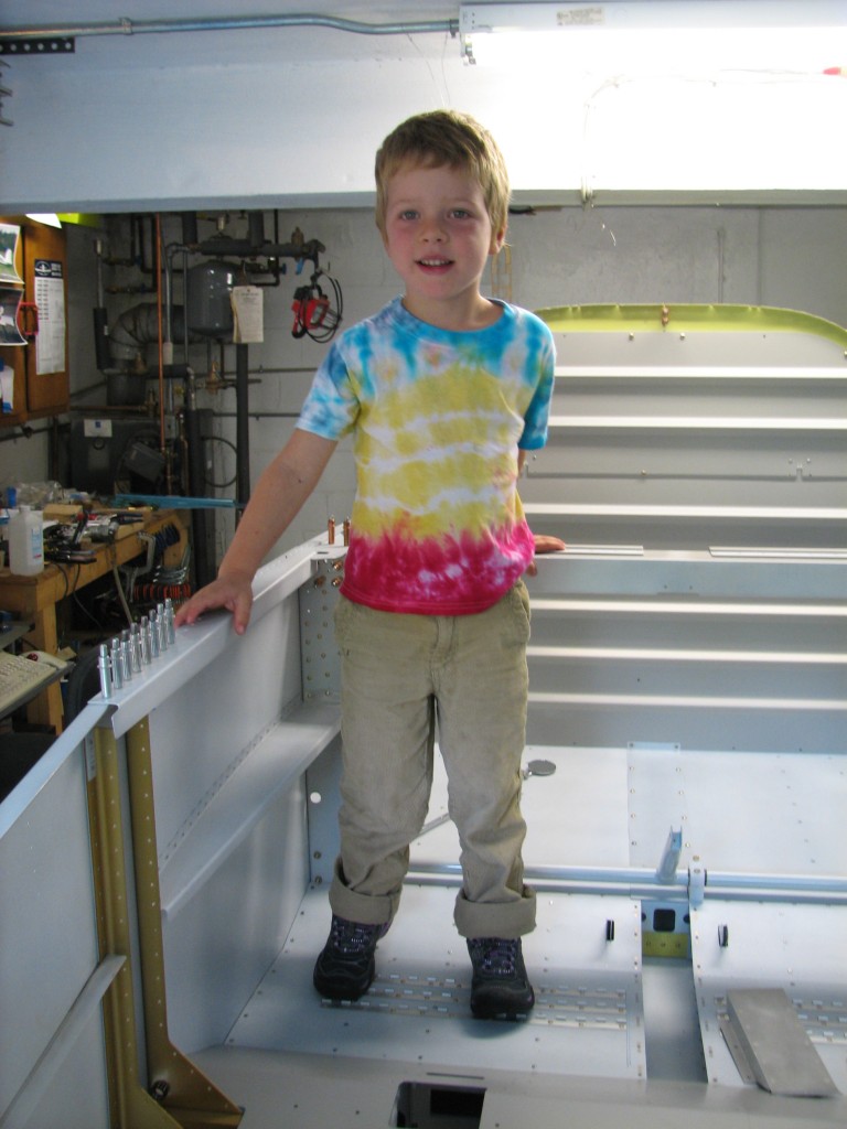 I had a special visitor during the flap marathon this weekend…my nephew Julian stayed with us for the day and came down to the shop. He’s into trains right now, but we’re working hard to get him hooked on airplanes!
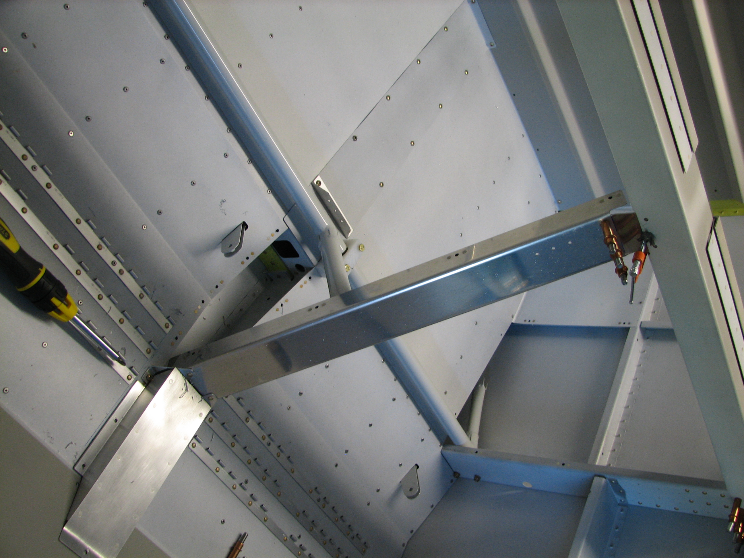
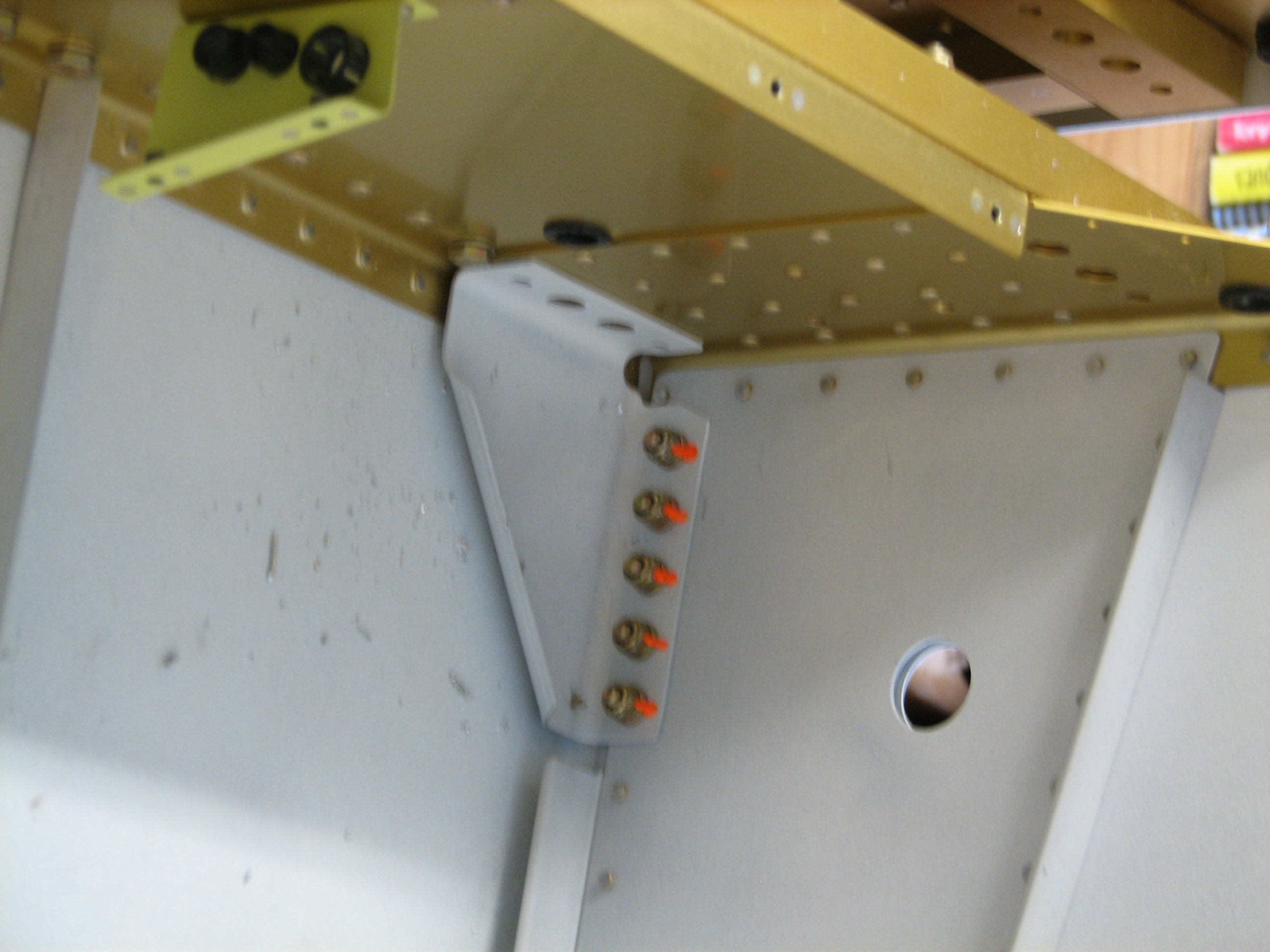
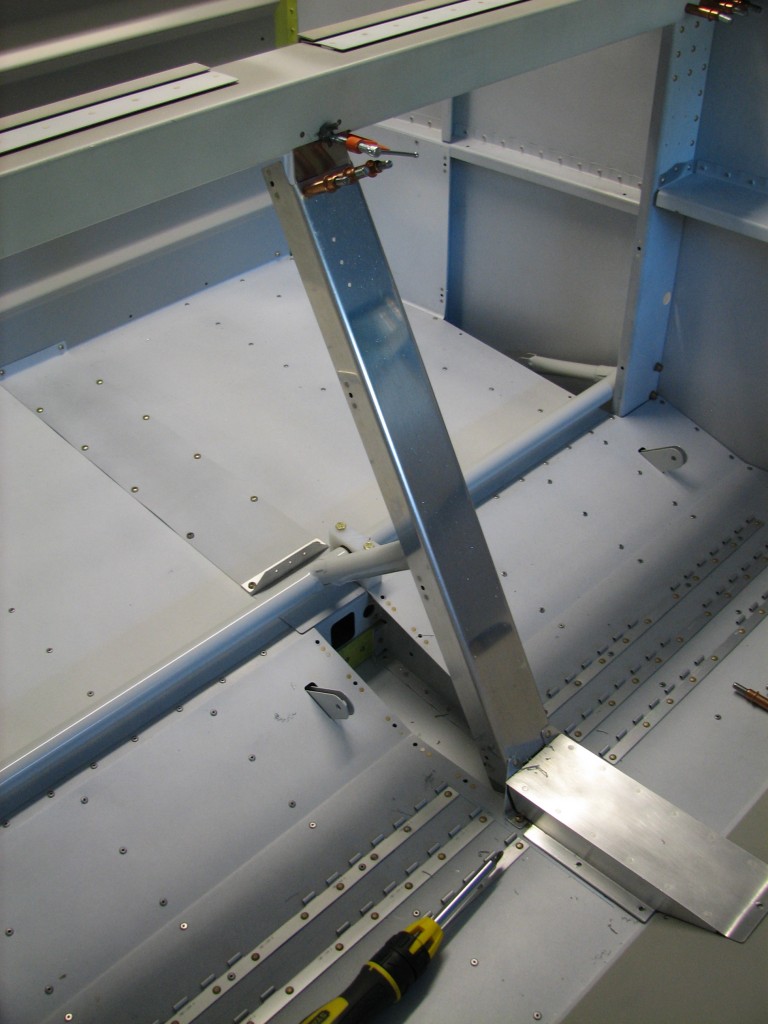 I didn’t take many pictures while assembling the flap housing. Here’s the forward, and most structural, flap housing brace where the flap motor attaches. At the top I clamped into place a small, angled splice plate that’s about to be match-drilled to the seat back and brace. At the bottom, I’ve already riveted two small angles that connect the brace with holes and nutplates on the floor.
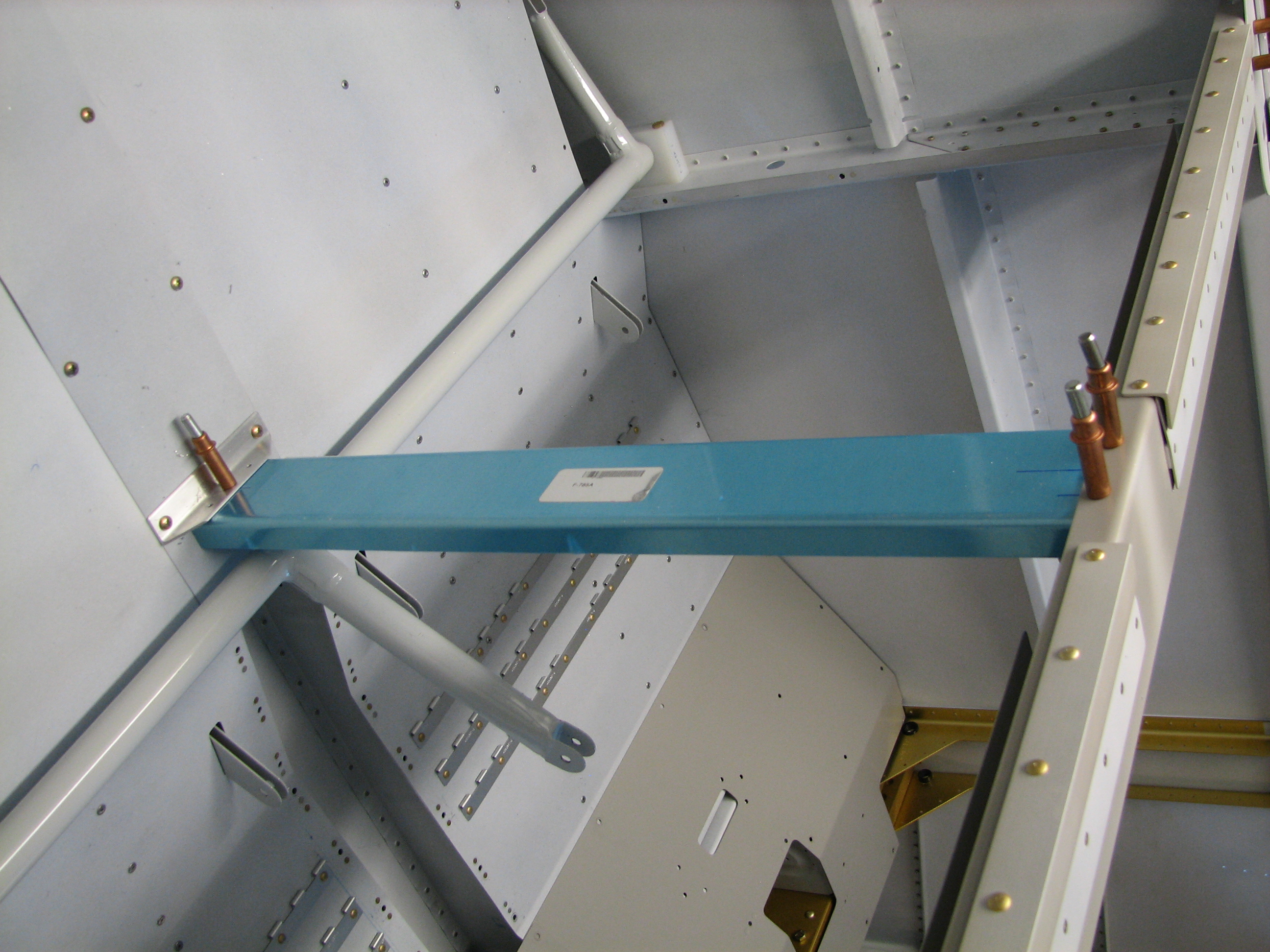
 The seat floor tunnel cover will need a little tweaking to fit next to the forward brace…nothing that can’t be handled by judicious application of a mill file and scotchbrite pad.
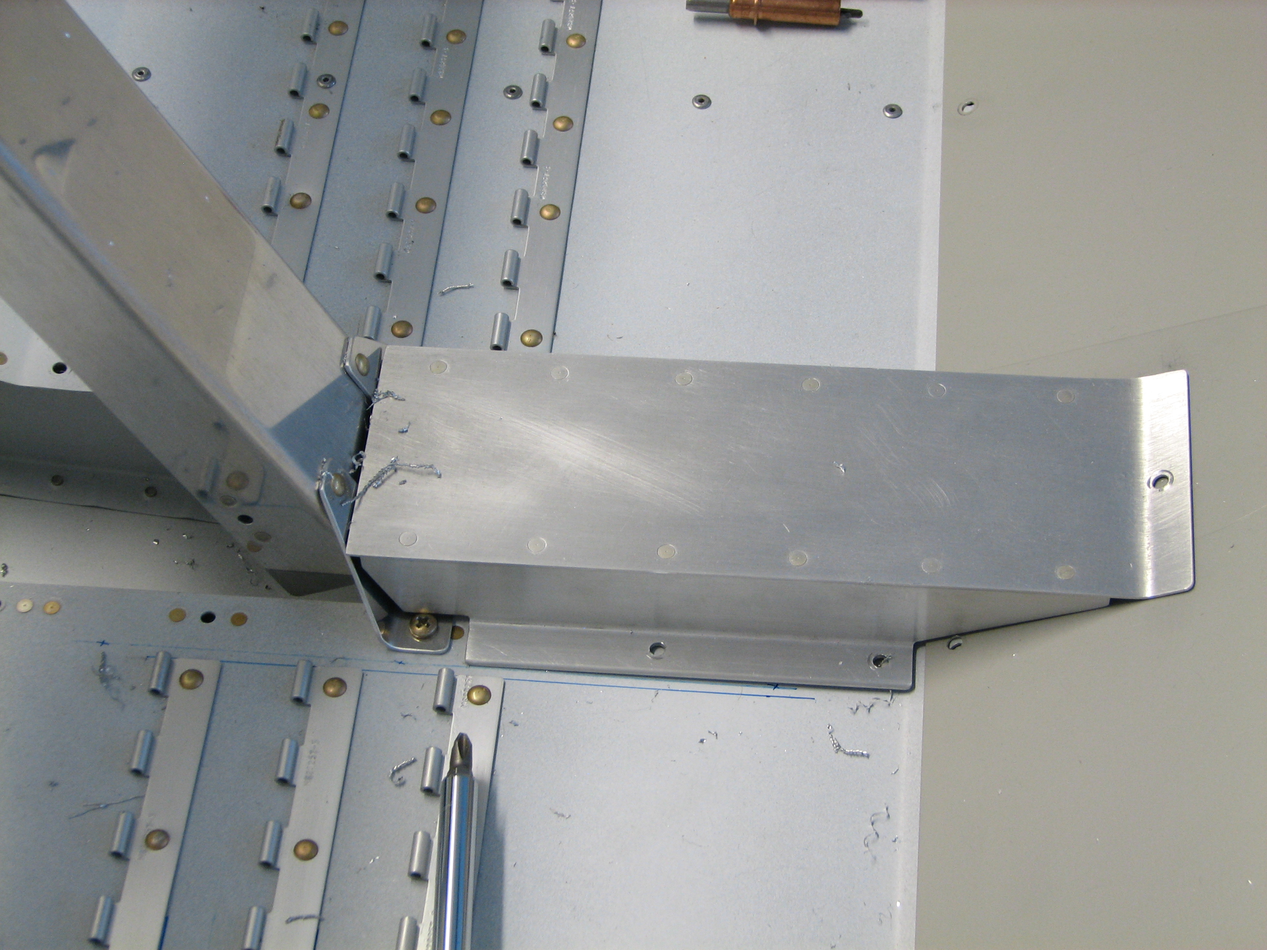
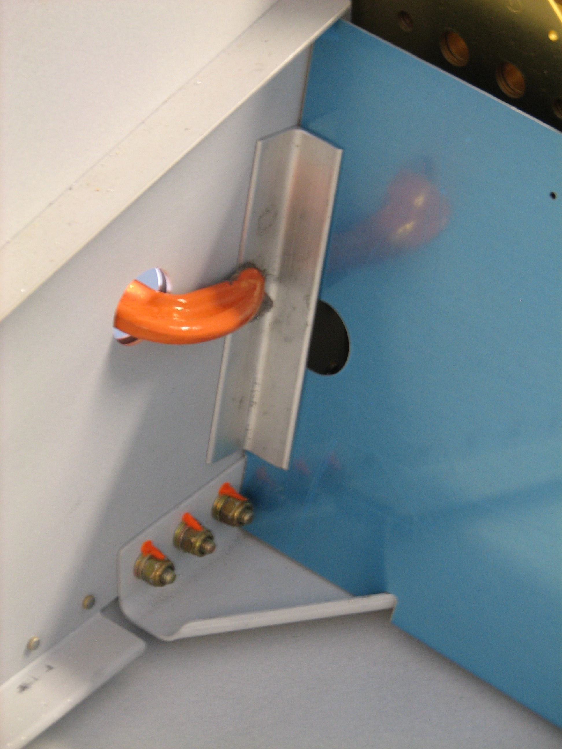
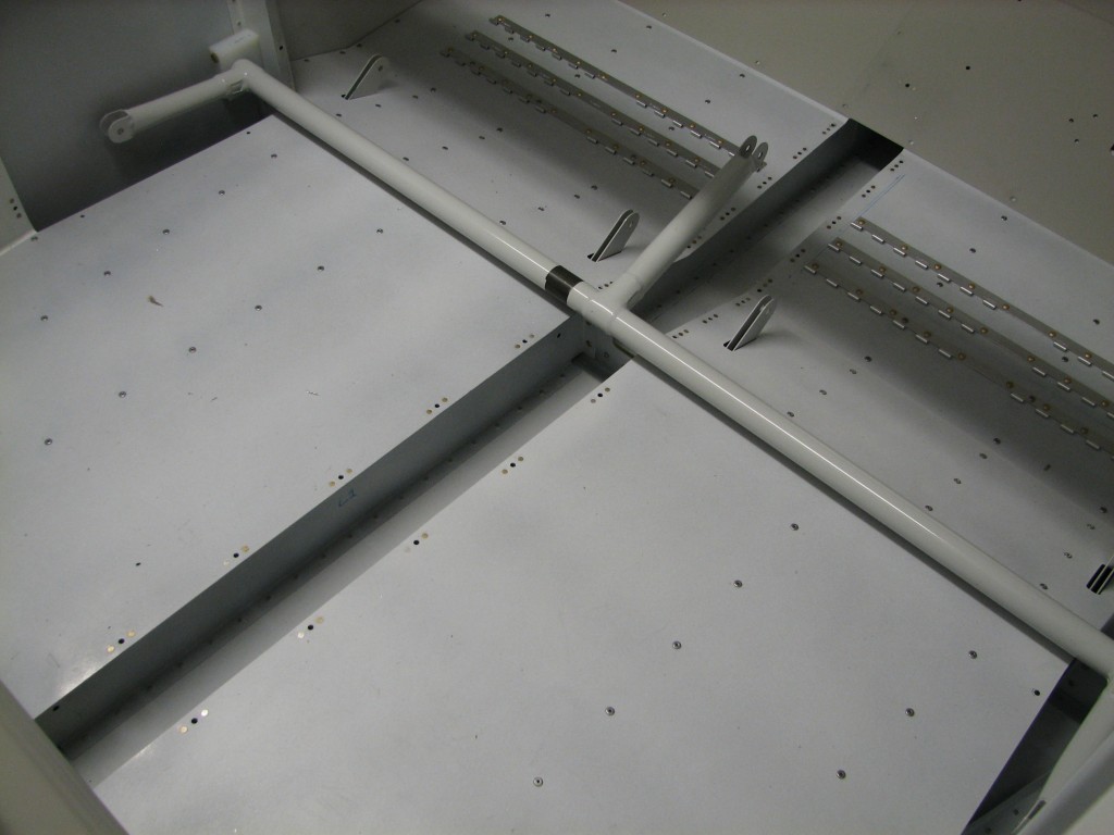
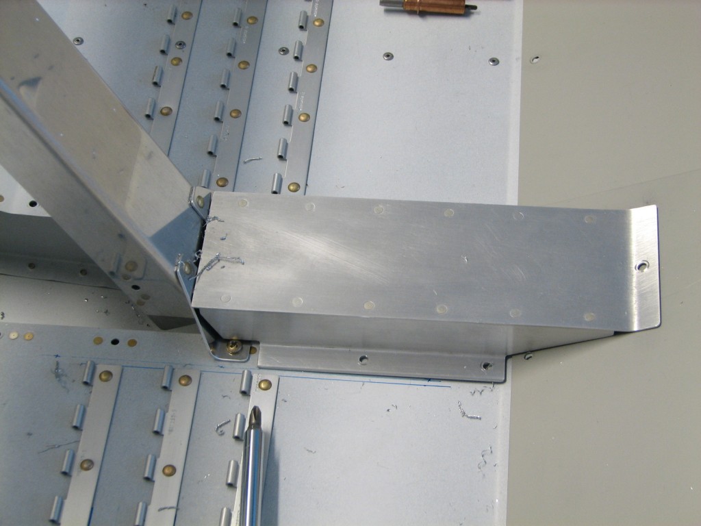
 Here’s the back part of the flap housing. Nothing too sexy here, just a c-channel and piece of angle match-drilled to the rear tunnel cover. The top is match-drilled to the seat back. The only slightly tricky part is centering the channel on the seat back; I measured the distance between the prepunched seat back holes, and used that measurement to lay out a couple of reference lines on the channel so they’d be visible through the seat back holes.
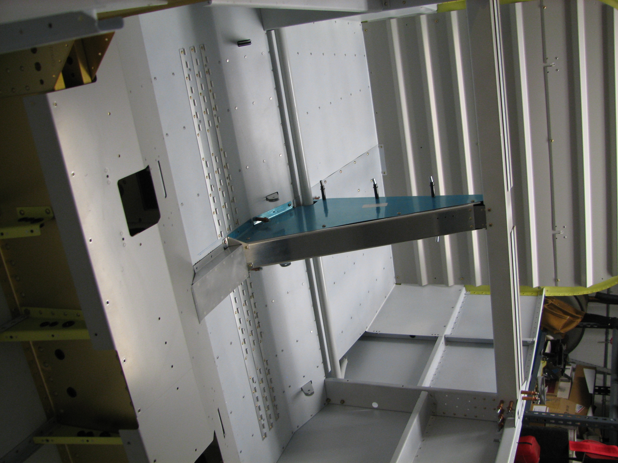
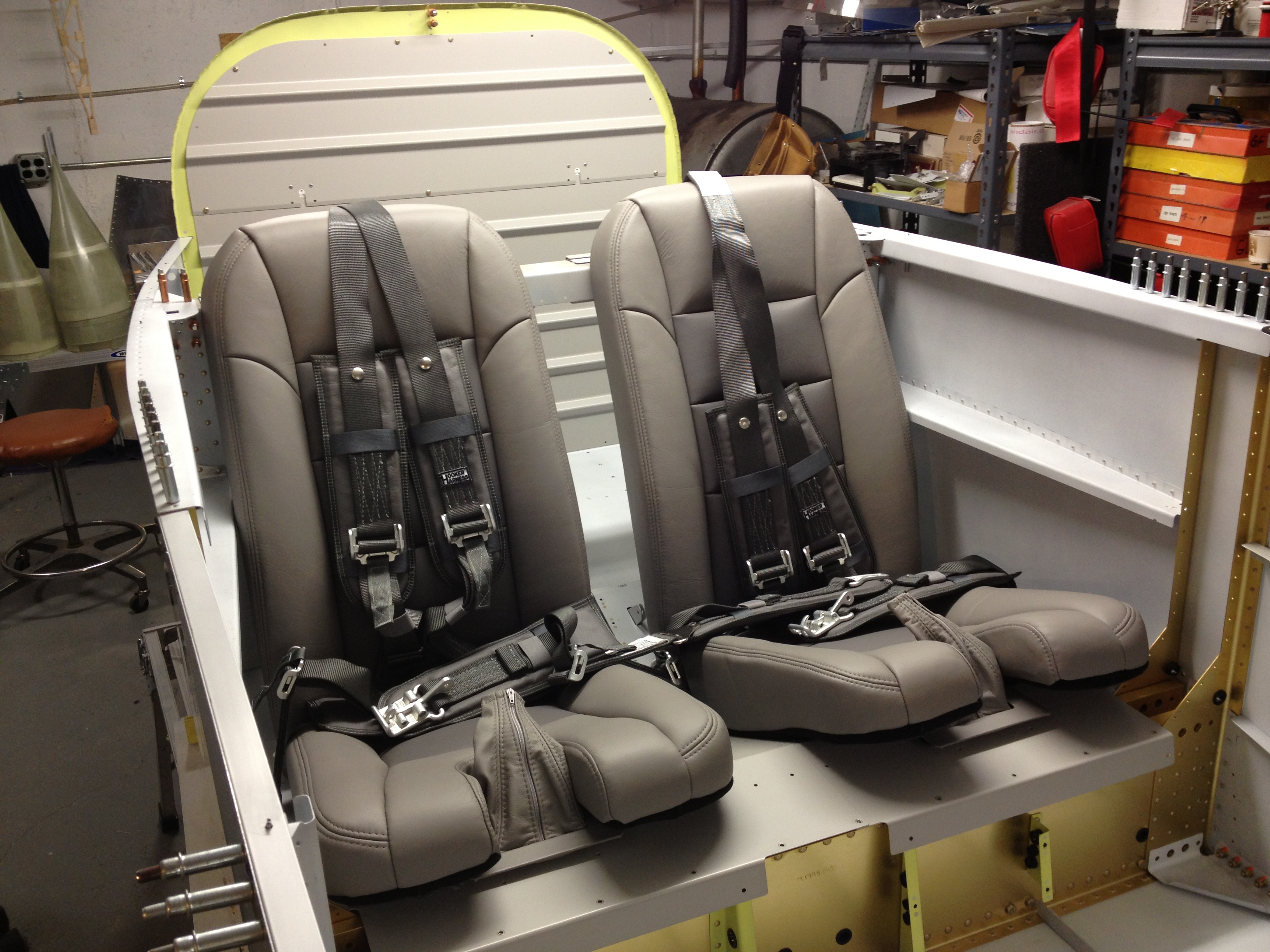
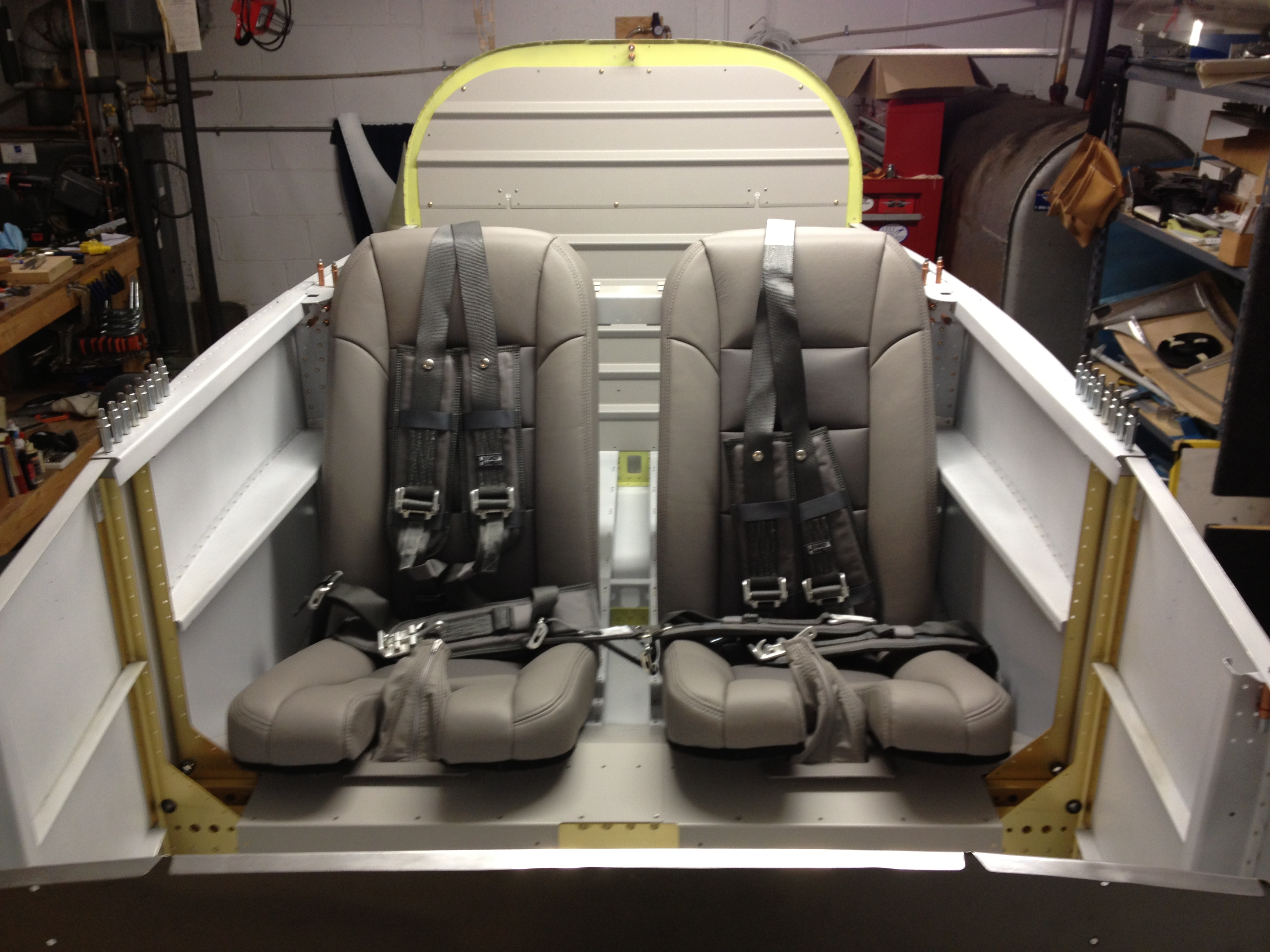
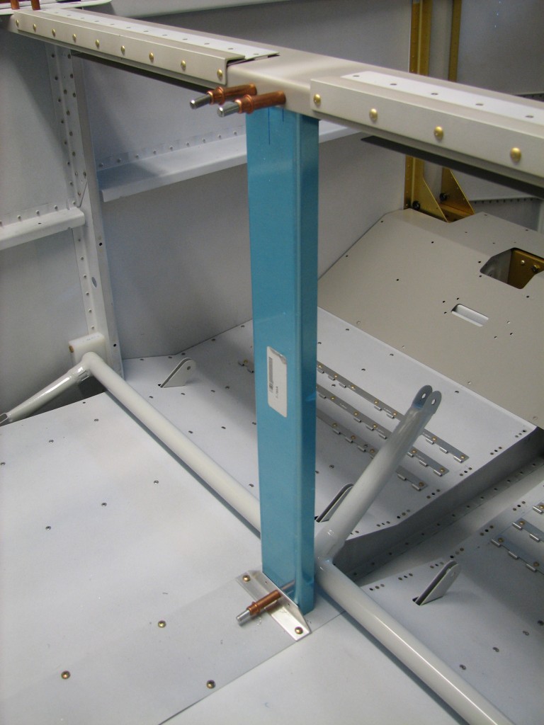
 Here’s everything all match-drilled and clecoed together. The side panels are very thin and don’t snug down very well on the forward housing. I’ll brain out a fix for that later.

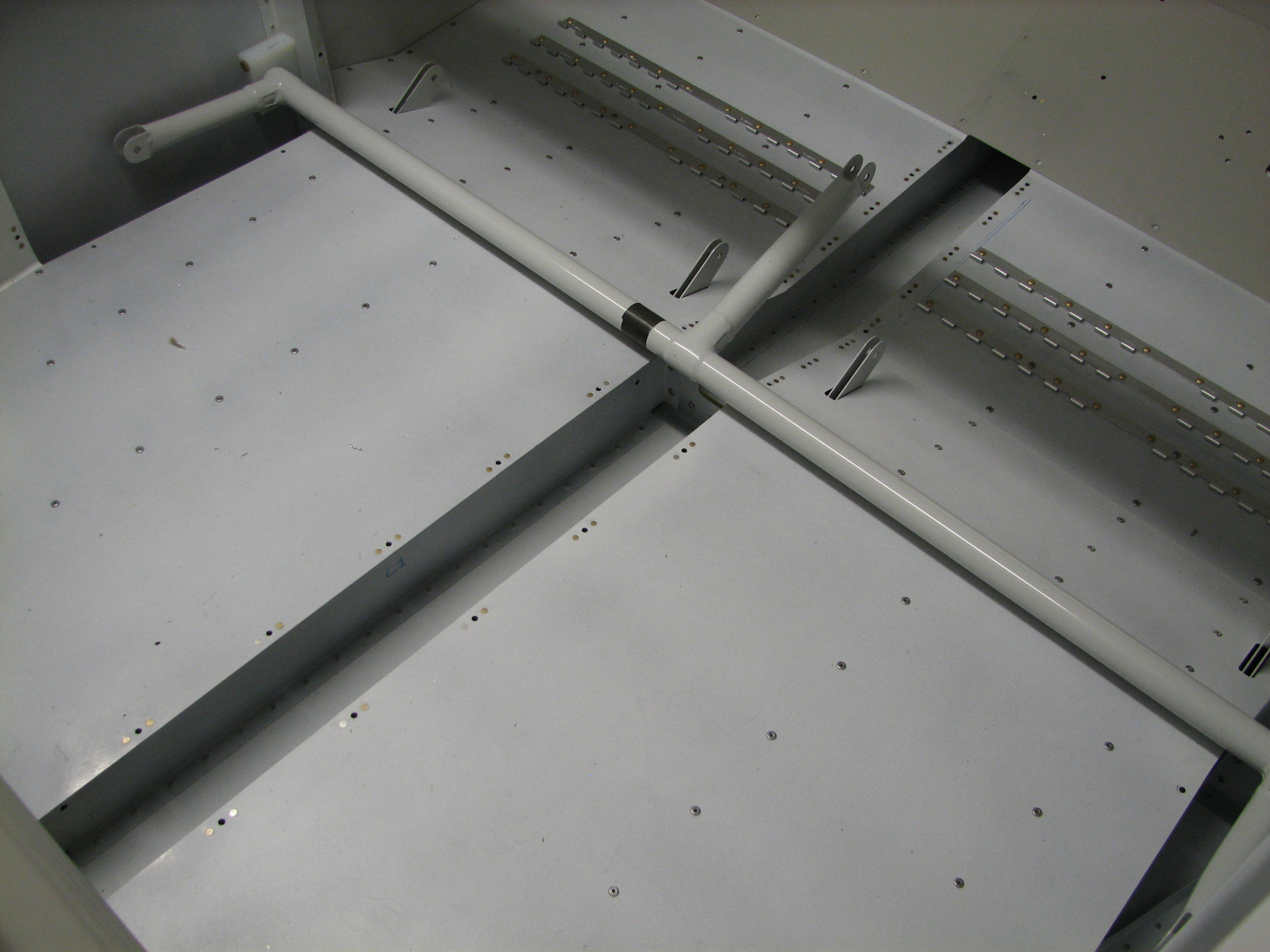
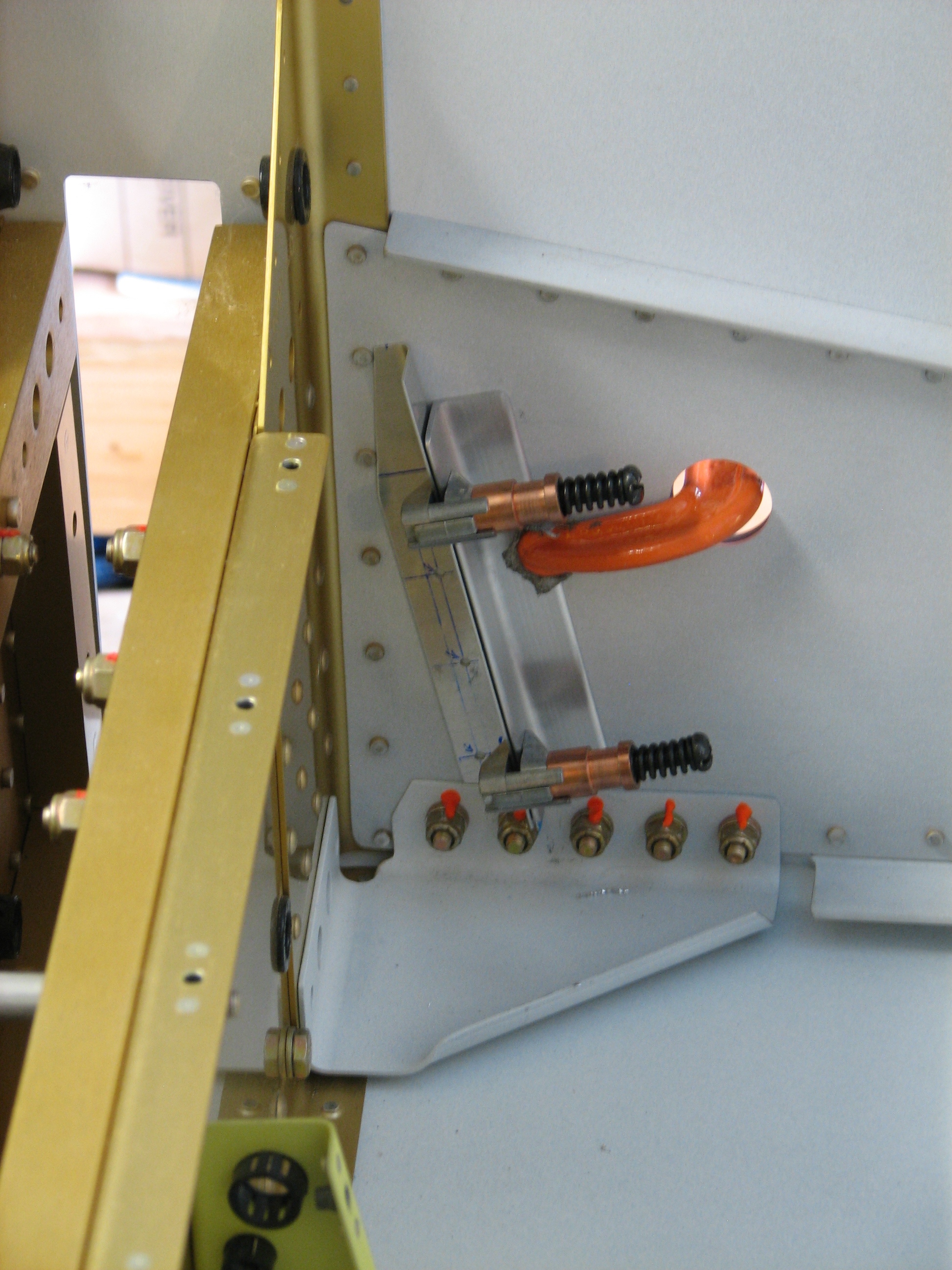
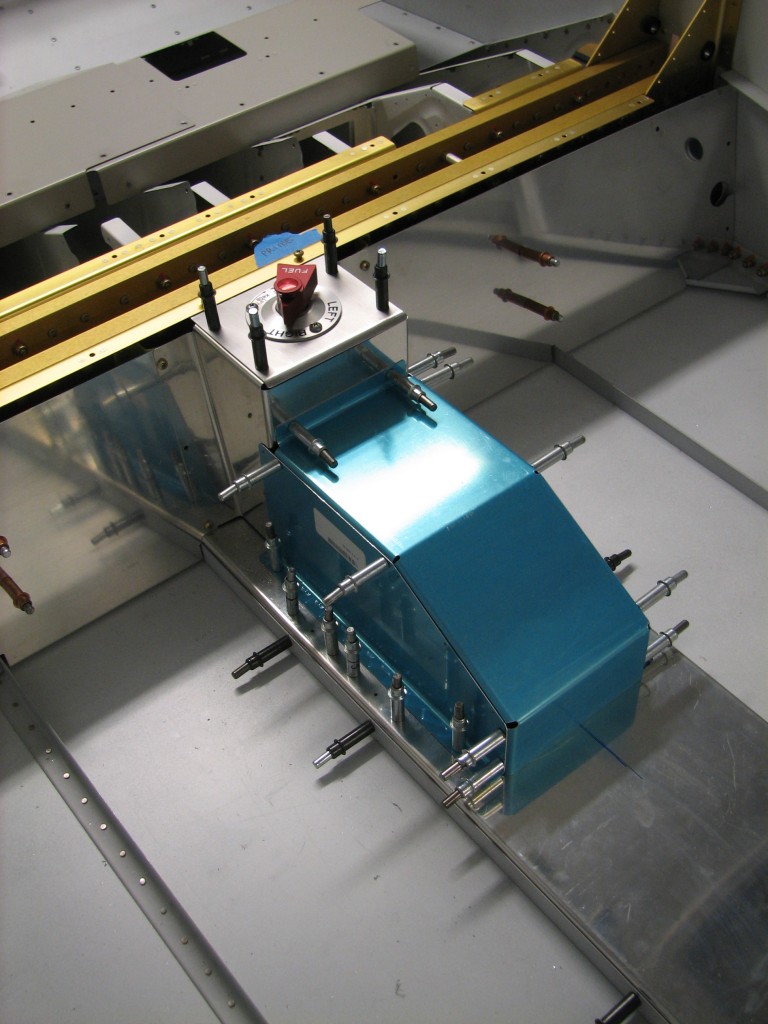
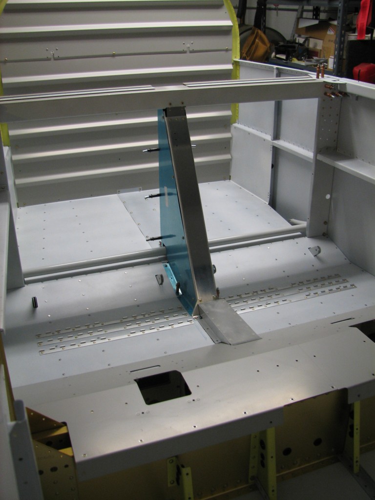
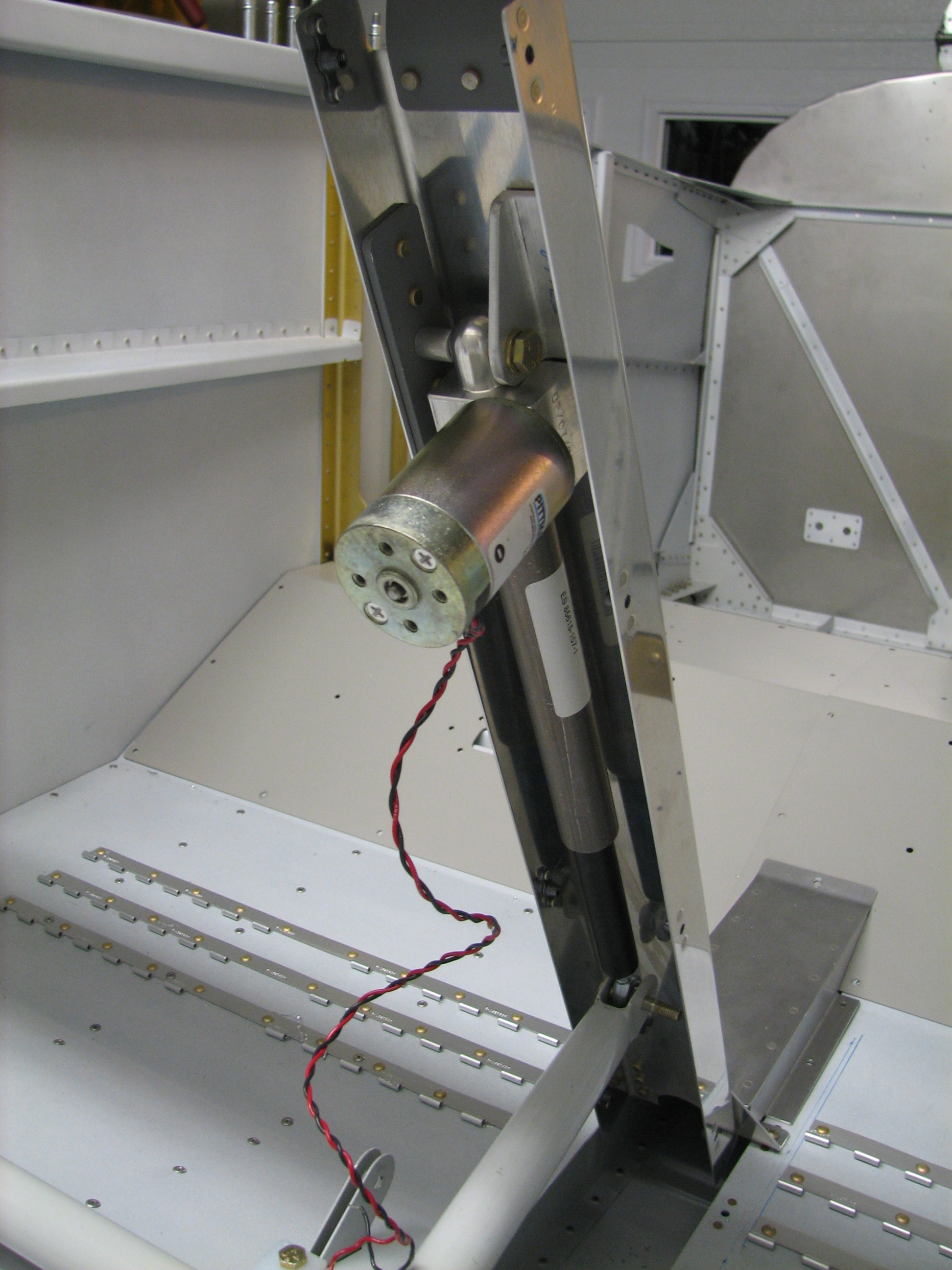 Second, and more importantly, I temporarily mounted the flap actuator to its housing. There’s one aluminum angle supporting the flap actuator that still needs to be mach-drilled to the forward brace – you can see the angle above and very slightly to the right of the actuator motor (for all you non-RVers, it’s the cylindrical thing with screws on the end).
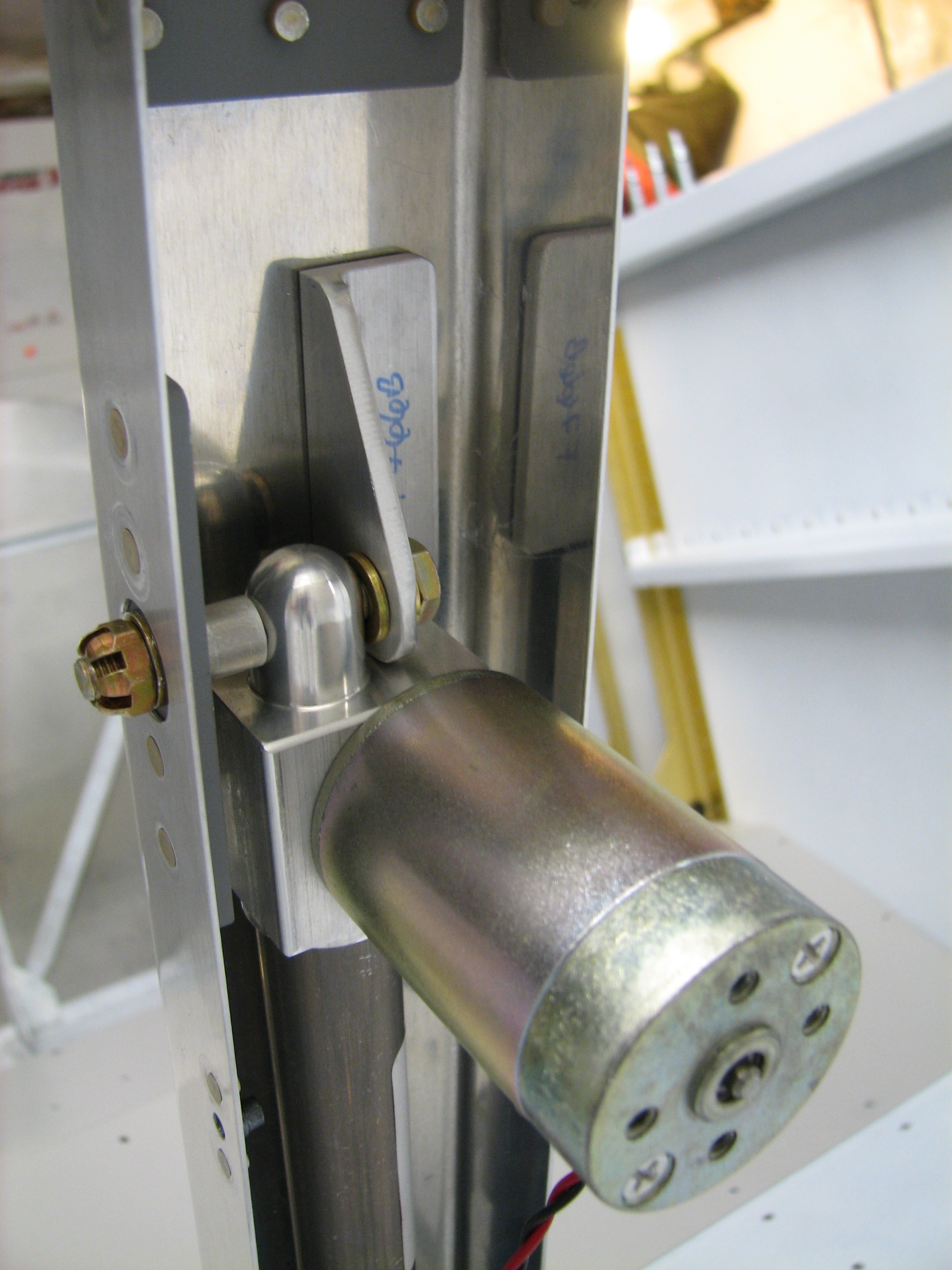 Here’s a closeup of the angle. One of the cool parts of this process is powering up the actuator with a battery to run out the actuator arm so it can be bolted to the flap arm. The flap motor hasn’t been run in five years, but it worked fine.