…should be kicked in the ass then given a medal.

…should be kicked in the ass then given a medal.
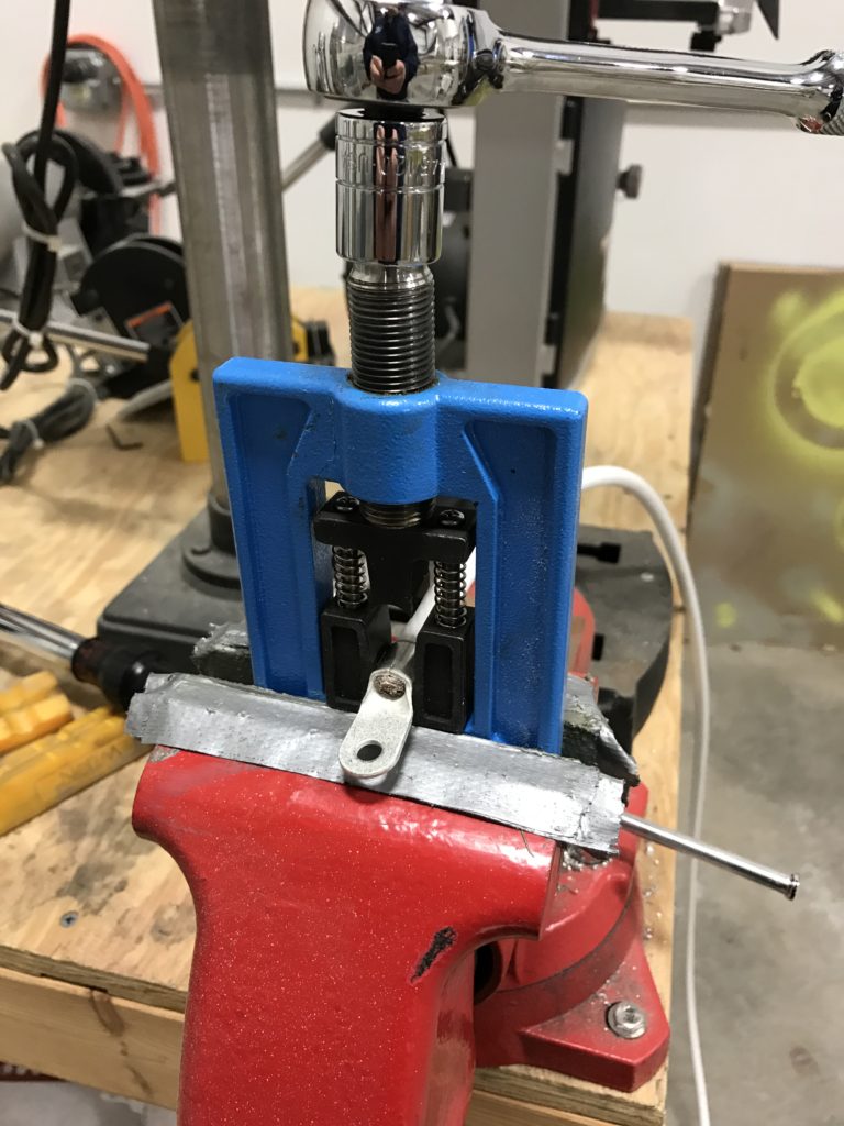
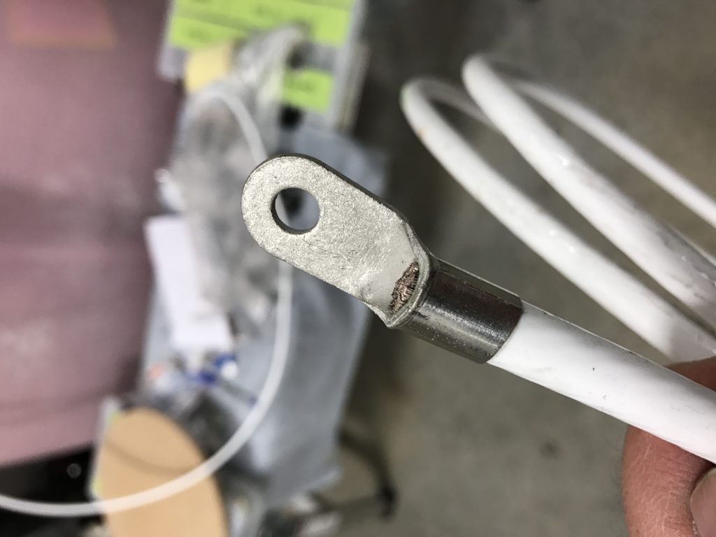
Sometimes you see a really cool tool that you think about buying, but you don’t need it at the time – and when you do need it, it’s no longer available. Such is the case with the Terminal Tool.
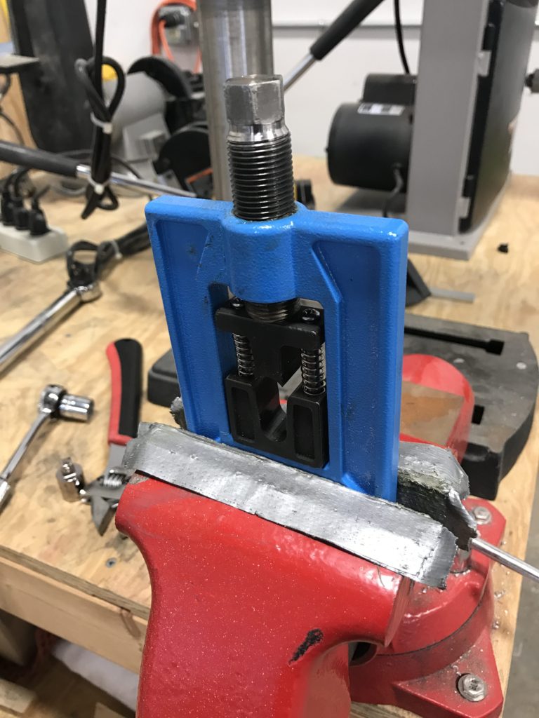
I had originally bought a hydraulic crimping tool from Harbor Freight, but the dies that came with it weren’t compatible with quality Amp terminals.
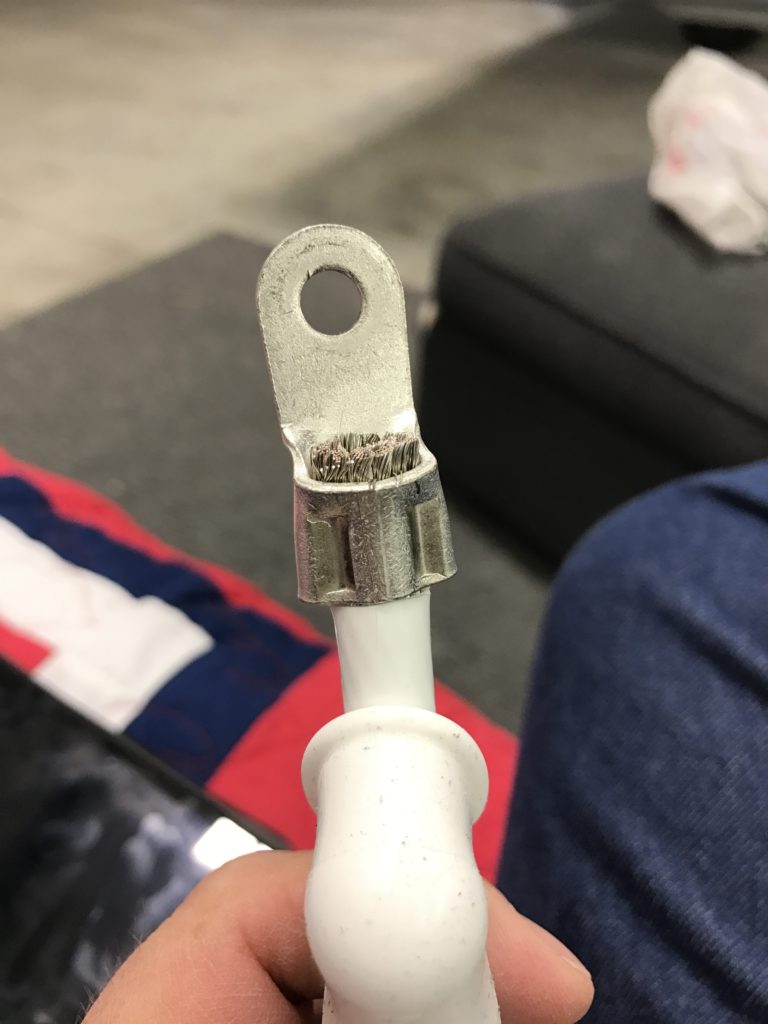
Fortunately, a friend and fellow RV builder at KASH had a Terminal Tool. It’s easy to use, and makes first-rate crimps on large cables.
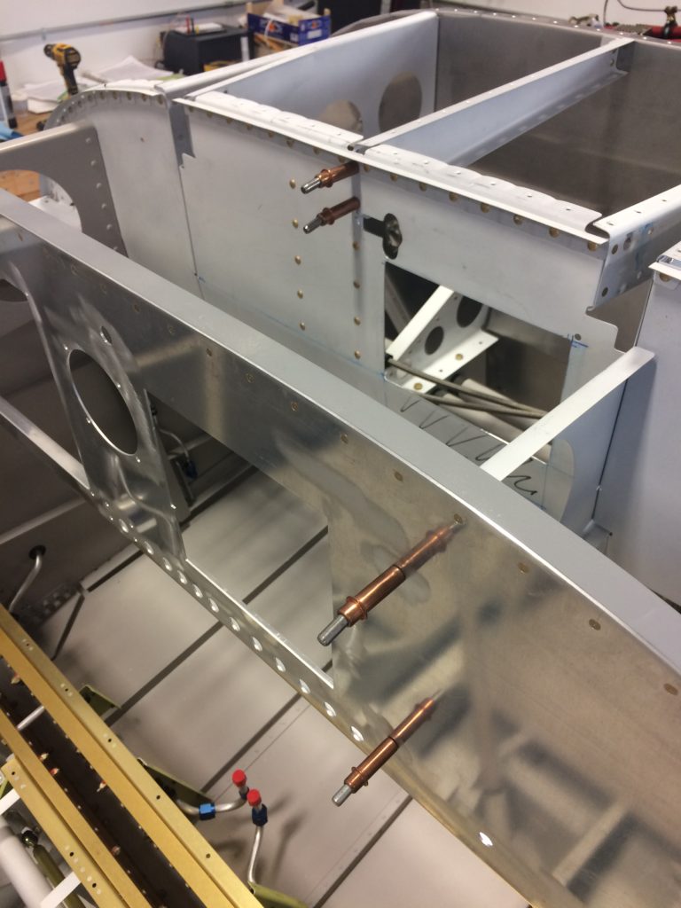
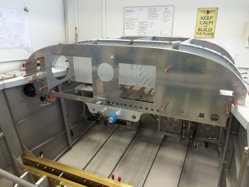
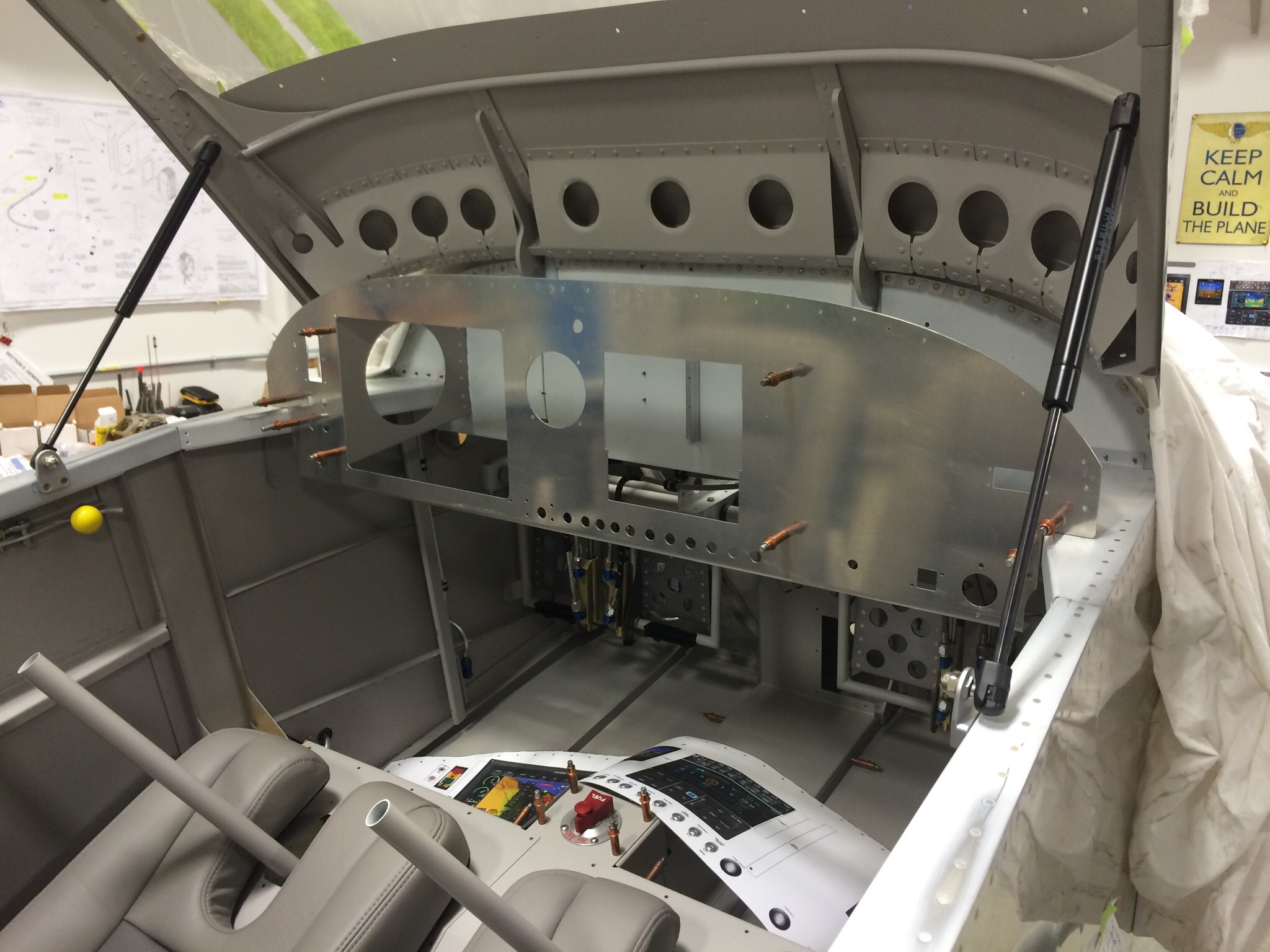
Getting a little frustrated with tweaking engine stuff, so in preparation for permanently installing the subpanel I started working on fitting the avionics racks.
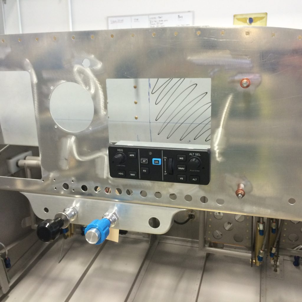
The GMC-307 autopilot controller was easy.
Wasn’t so easy to get a correctly-aligned hole in the subpanel to accommodate the GTN-650 rack (the comm/WAAS GPS/VOR/localizer/ILS does-everything box).
Also had to make sure the GTN-650 and GMA-245 (that’s the audio panel) racks were correctly spaced from each other.
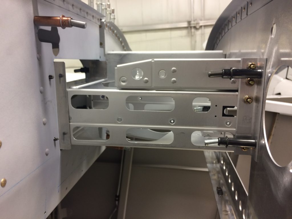
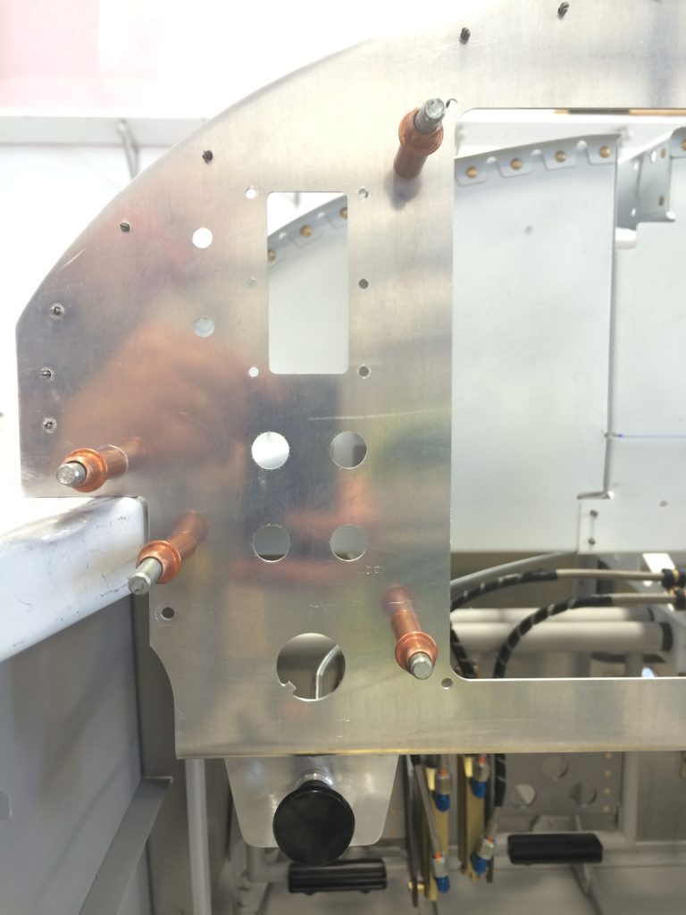
Took a lot of filing and fitting to get to this point. The rear rack mount “ears” are actually riveted to two 0.063″ angles that will be held in place by nutplates. I would’ve preferred just to attach them to the front side of the subpanel, but the rack attachment fasteners are too close to the subpanel to allow that.
A nice bit of visual progress, don’t you think?
…I hope.
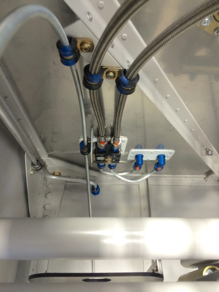
I wrote it to Tim Hass and the folks at Approach Fast Stack for a Garmin 10.3″ G3X Touch EFIS system with Sirius XM, GTN-650 GPS/Nav/Comm, GTX-45R ADS-B In/Out transponder, GMA-245 audio panel, GMC-307 autopilot mode controller, two GSU-28 autopilot servos, and all the associated Garmin boxes that go into a G3X installation.
All these gadgets will be connected to one of Tim’s Fast Stack Pro-X hubs, which will make wiring significantly easier and neater.
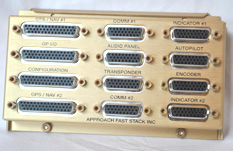
It’s worth the (relatively) few extra dollars to speed up avionics installation, and the resulting product will be a lot easier to upgrade should I ever want to.
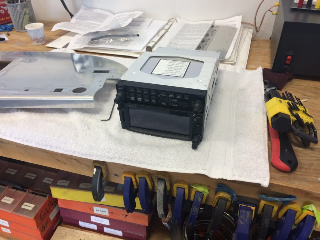
Two really expensive boxes…
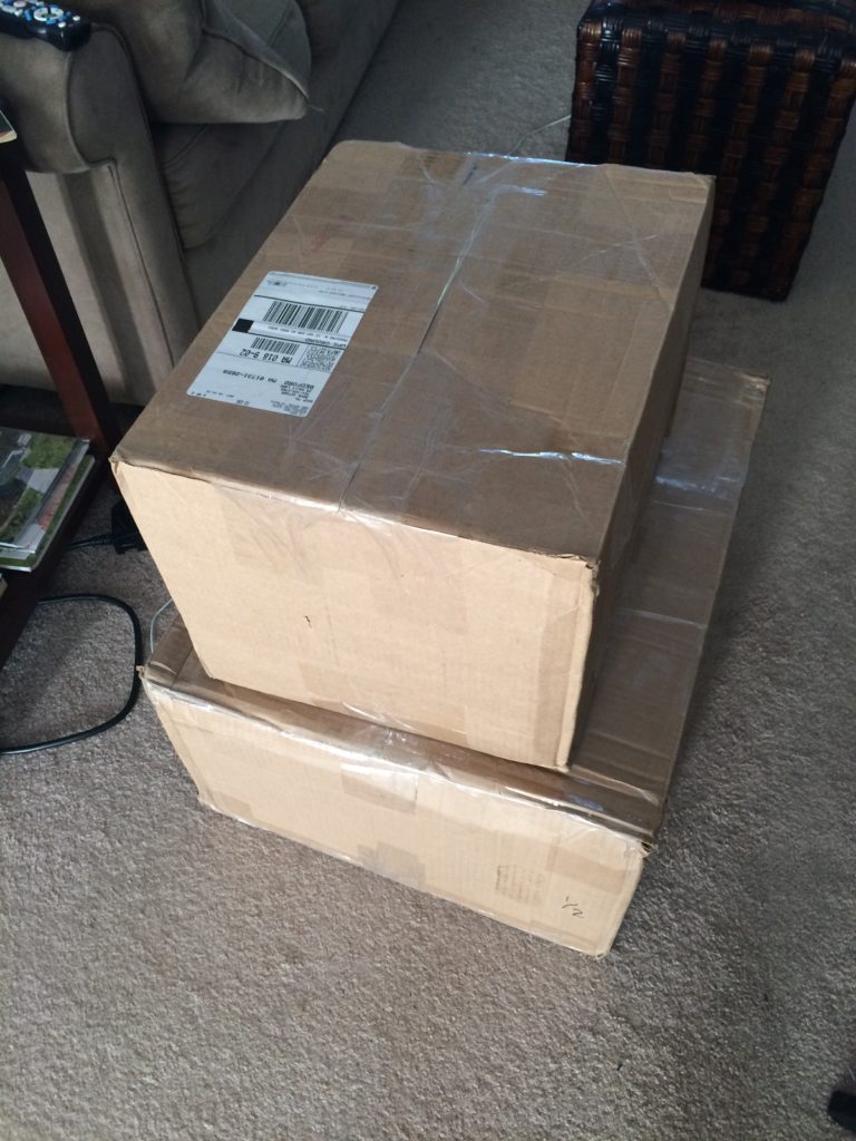
…and their contents.
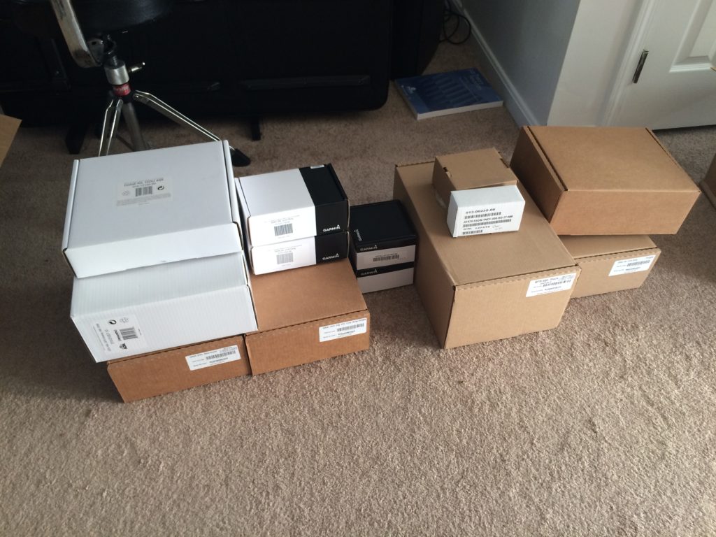
So why all the screws?
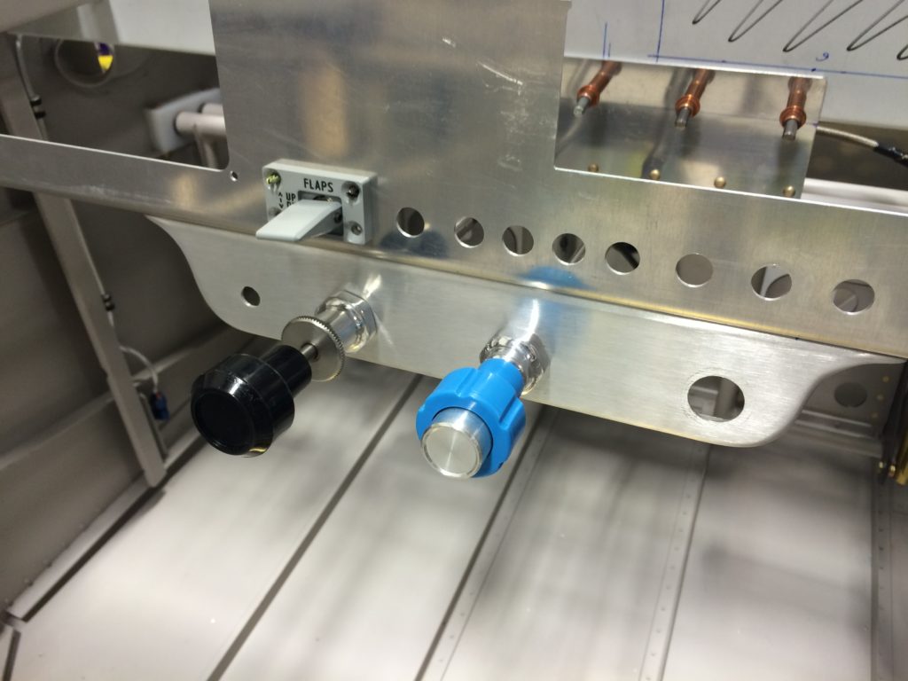
Working on the instrument panel and controls while waiting for engine parts.
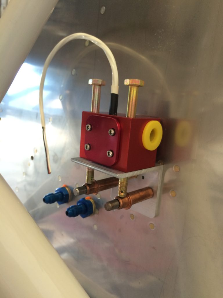
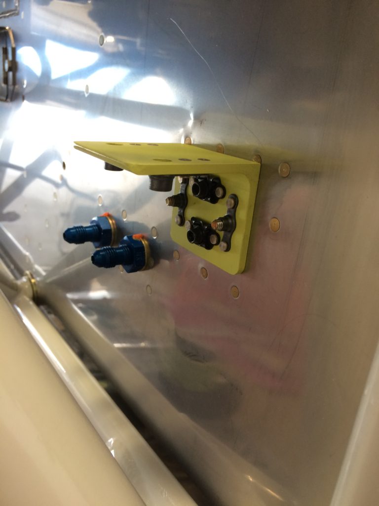
Parking brake control bracket
Panel with control brackets
Throttle and flap switch, the fit here is great.
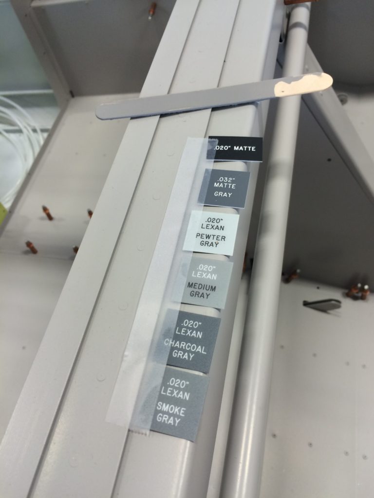
Background colors for panel labels
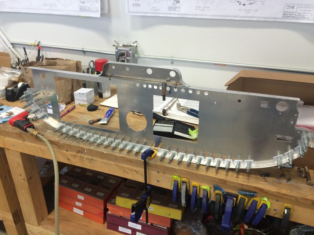
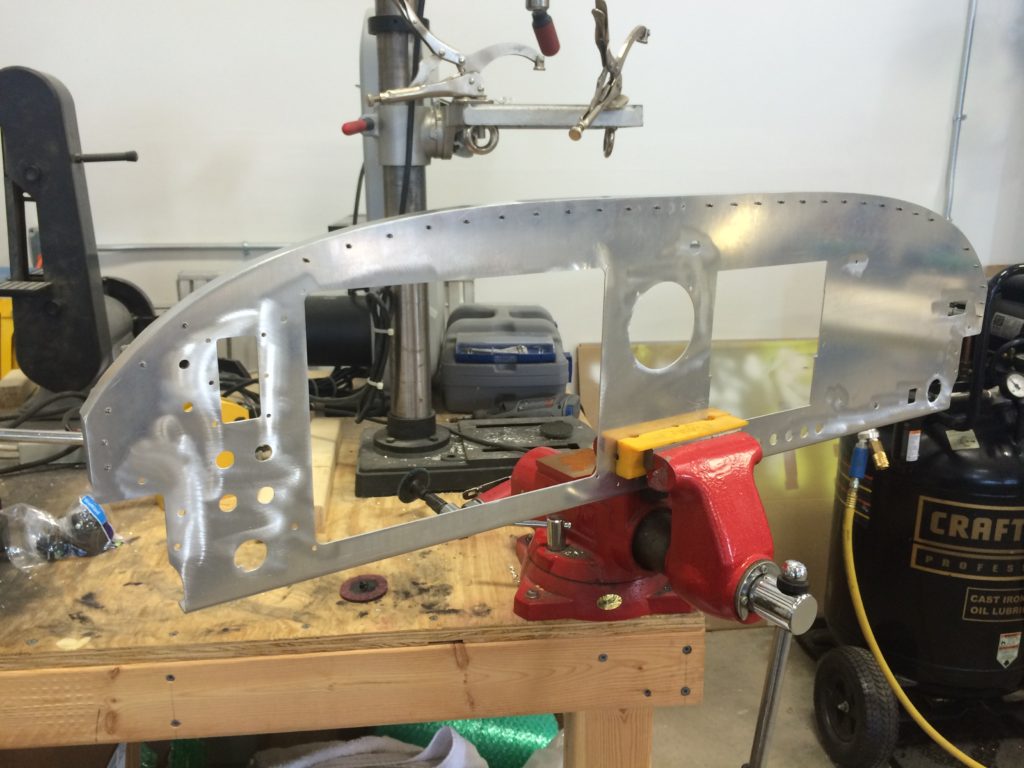
Prepping the panel for riveting
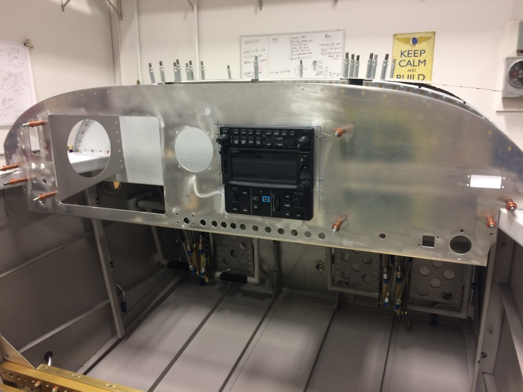
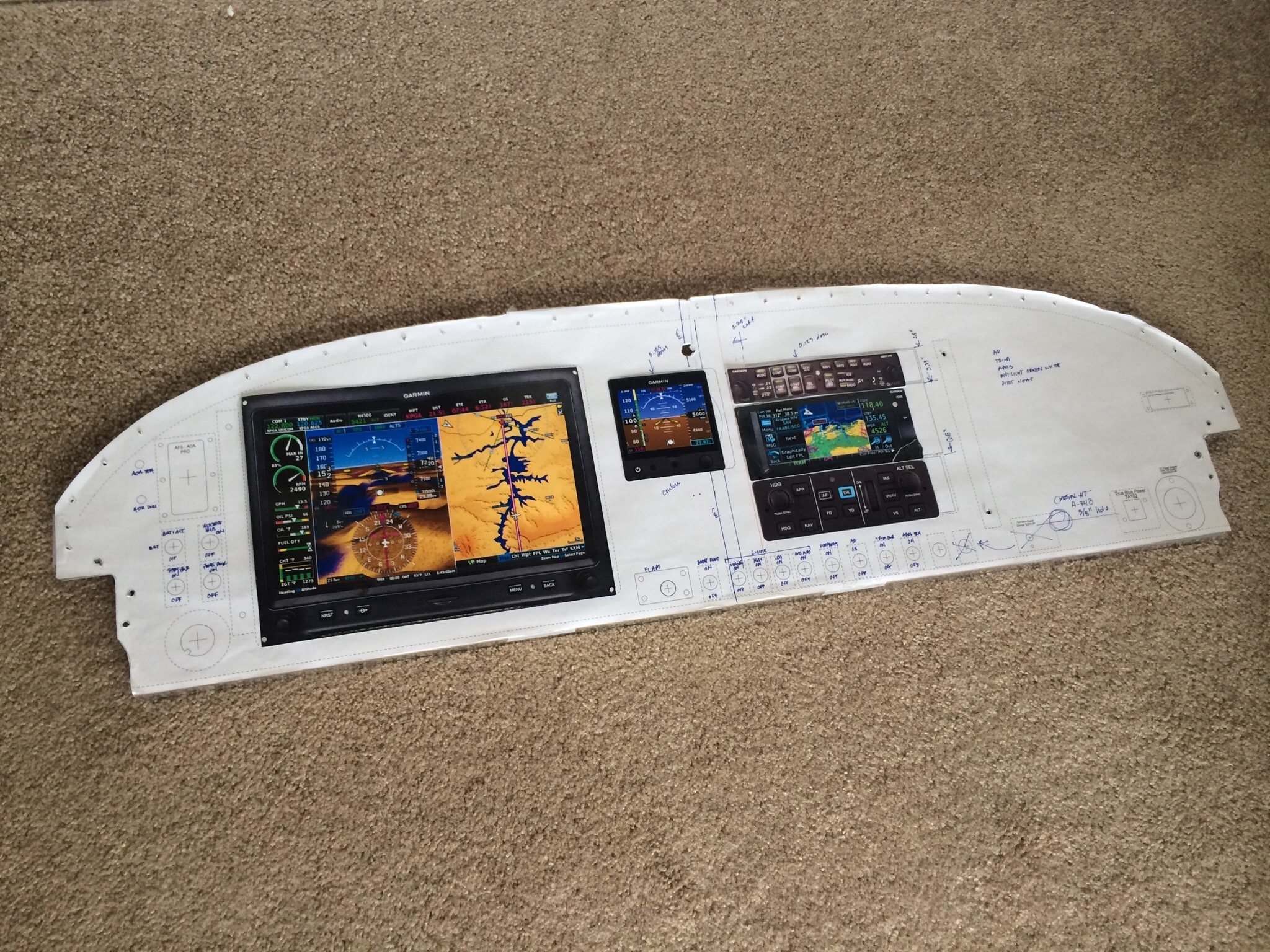
One of my side projects over the last several years has been designing and re-designing the instrument panel. This is one area that every new builder likes to jump into right at the beginning of their build, and it’s probably one of the last areas we should worry about because the experimental avionics market changes so quickly.
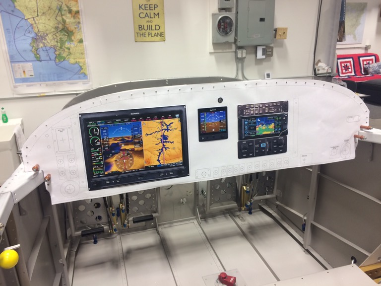
But I’m at the point now where I must make provisions on the instrument panel fo specific avionics, so it’s time to commit to avionics equipage and cut the panel. You can tell by the picture below that I’ve chosen Garmin avionics for just about everything except the Advanced Flight Systems AoA indicator.
I decided early on that I’d have the panel professionally cut so I needed to find a shop that could do the CAD layout and also had the ability to do CNC milling. There are lots of panel design and cutting providers on VAF, but I’d heard good things about Bill Morelli at Up North Aviation in Swanton, Vermont and decided to give him a try. I’m glad I did.
I already had a basic idea of what I wanted in the panel, so I gave my ideas to Bill and he came right back with full-size CAD layout PDFs based on my inputs. For most iterations I’d have Kinkos print out the PDF at full size, cut out the panel from the print, overlay it on the blank aluminum panel, then make adjustments that I sent back to Bill for a new CAD layout. Bill and I went through this cycle many times, and he was extremely patient with all the little tweaks I requested.
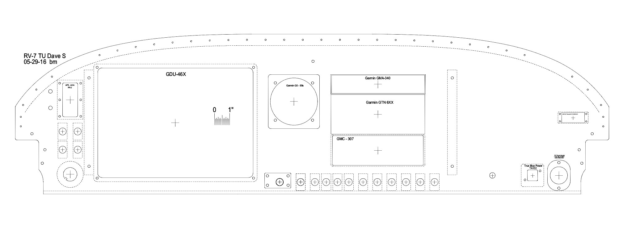
The above picture is Bill’s CAD rendering of my final design, and the picture below is the end result after Bill cut my panel.
I’m extremely pleased with how it came out!
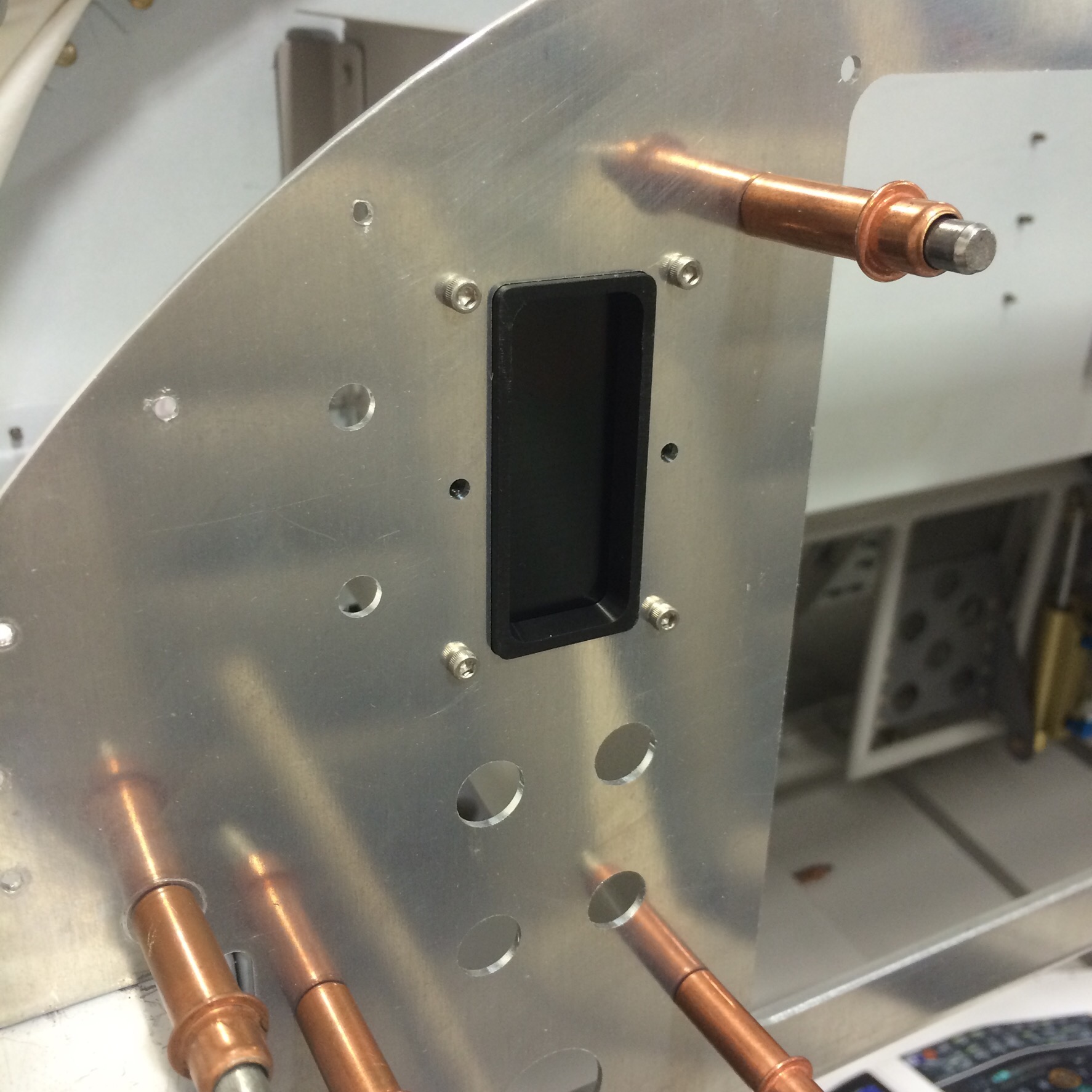
Here’s one example of the quality of Bill’s work. I pulled out the Advanced AoA display head and temporarily attached it to the panel. The fit is practically perfect!
With the panel cut, I’m warming up my frequent-flier rewards card in preparation for big avionics buys at Oshkosh…