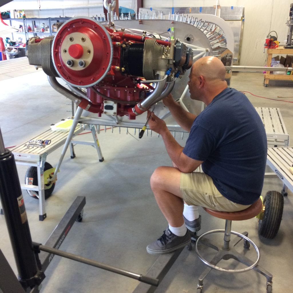
Had a few minutes to spare, so why not install the alternator?
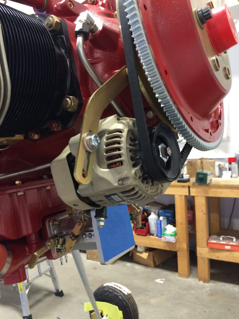
The tensioner arm and pivot bolt still need to be torqued, but that’ll wait until the prop is on and the alternator belt is correctly tensioned.

Had a few minutes to spare, so why not install the alternator?
The tensioner arm and pivot bolt still need to be torqued, but that’ll wait until the prop is on and the alternator belt is correctly tensioned.
Working on the instrument panel and controls while waiting for engine parts.
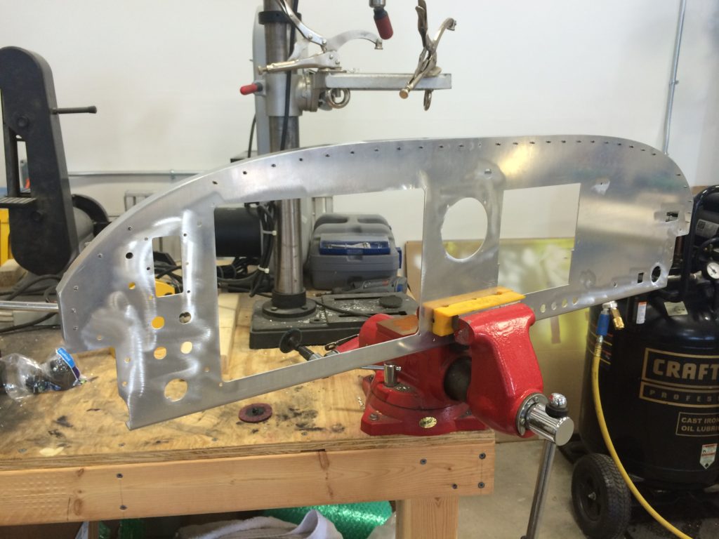
Parking brake control bracket
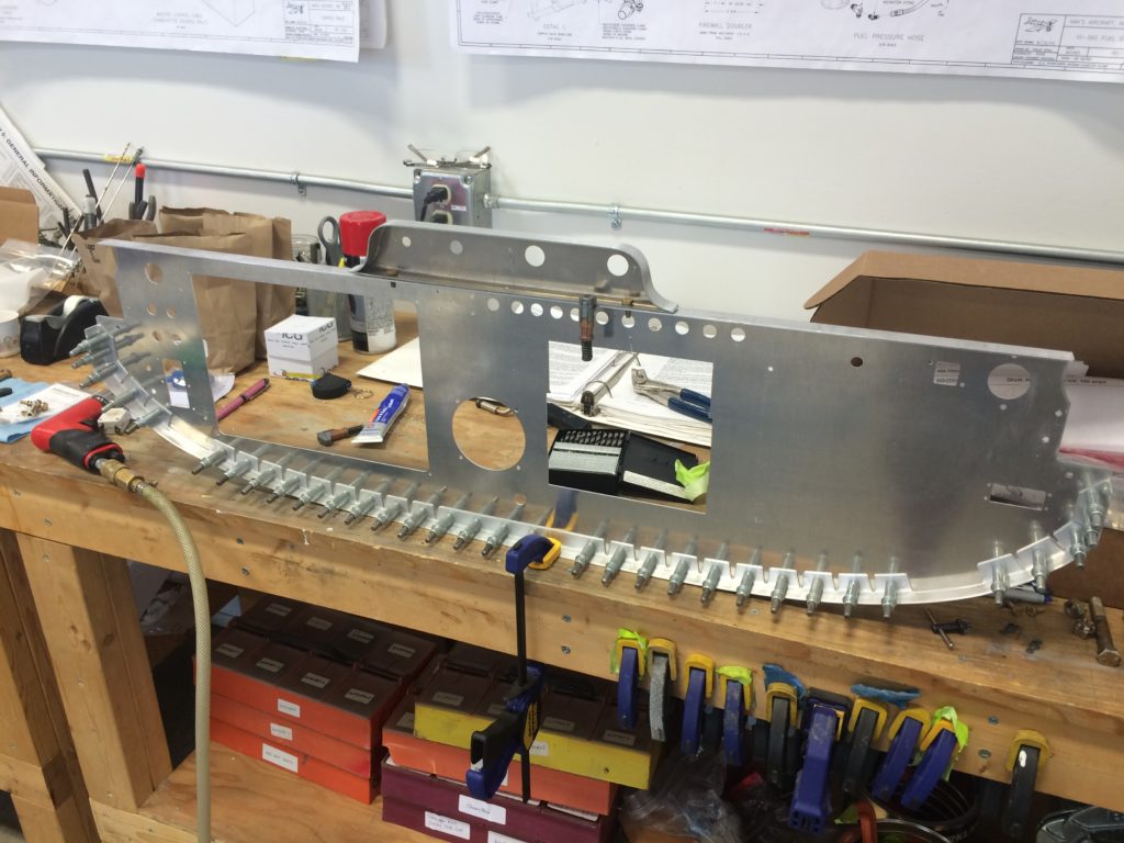
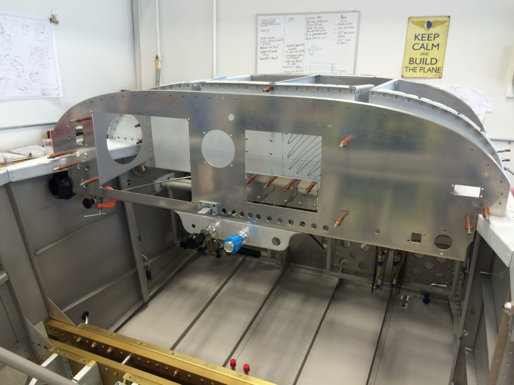
Panel with control brackets
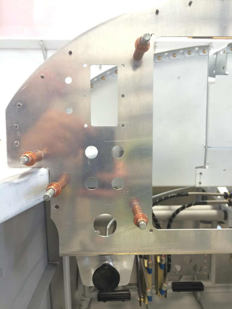
Throttle and flap switch, the fit here is great.
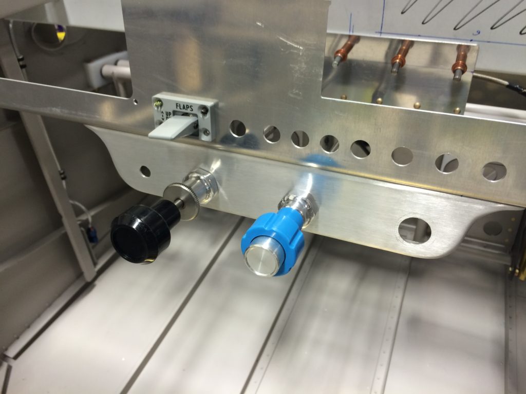
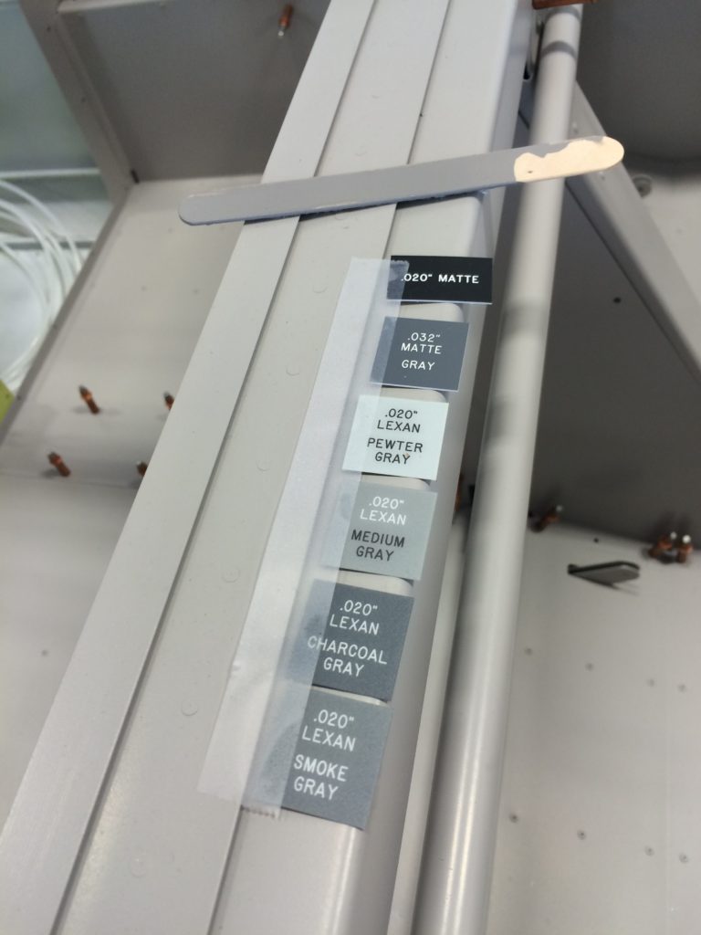
Background colors for panel labels
Prepping the panel for riveting
I’m finally getting caught up on all the missing text I didn’t add when I posted these pictures…
Like Unwrapping the PCU-5000 governor after 9-plus years of storage.
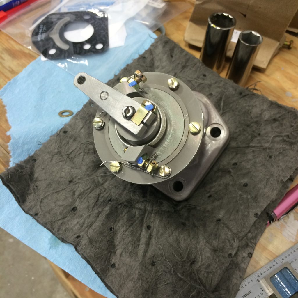
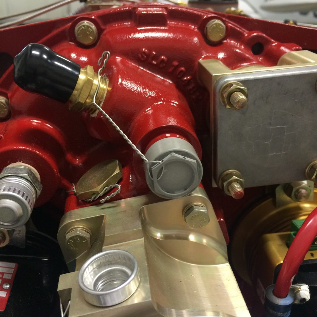
Installing longer mounting studs.
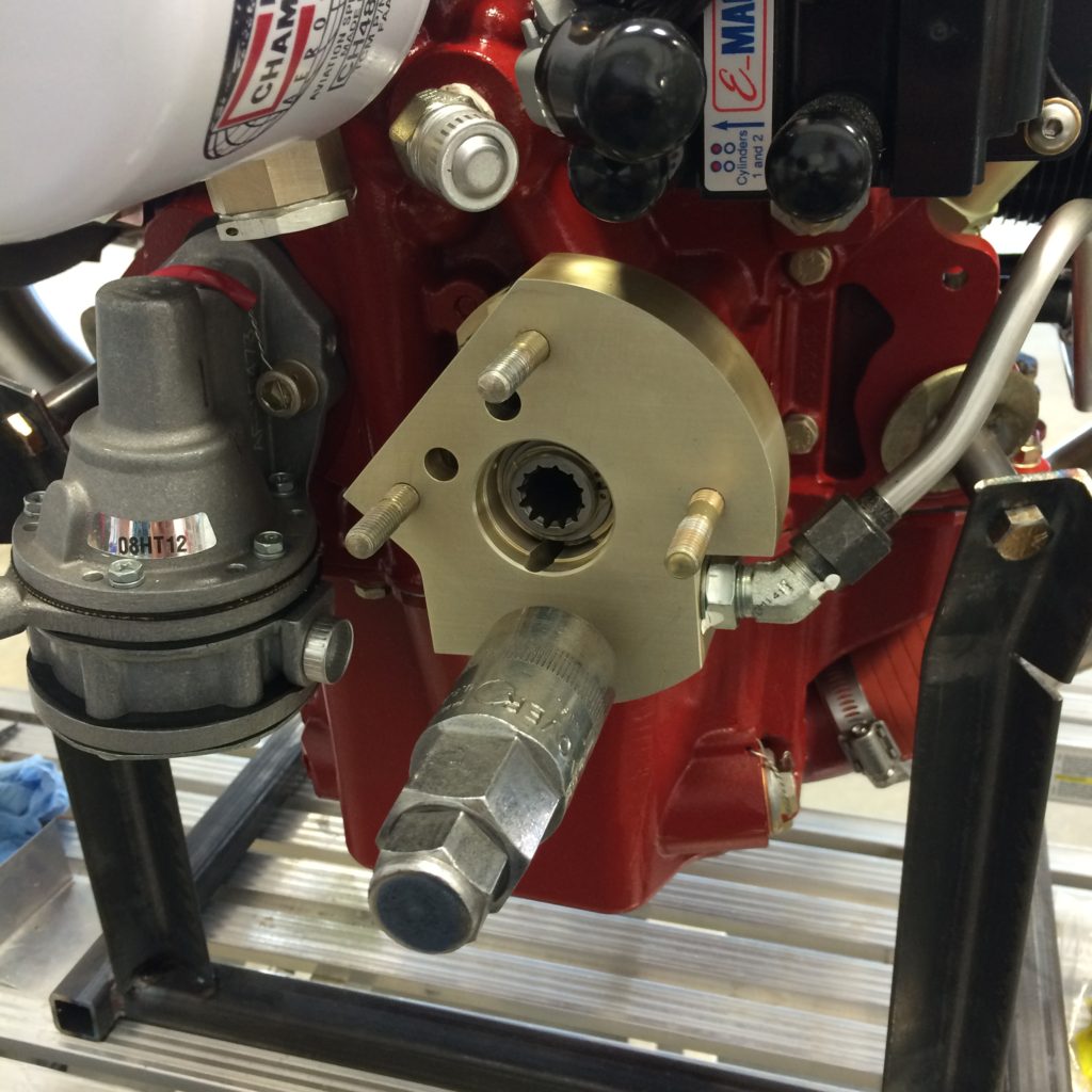
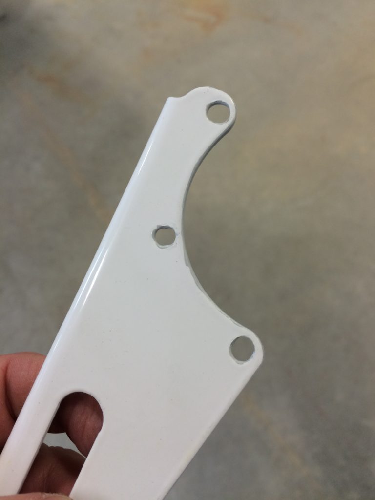
Adapting the stock Van’s governor cable bracket.
Governor cable bracket installed
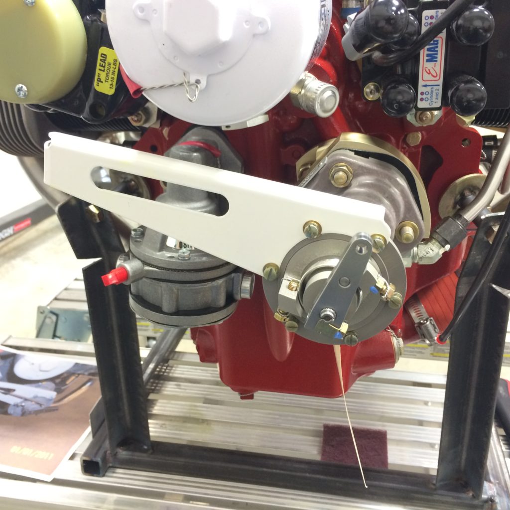
Tachometer drive cable installed.
One of my side projects over the last several years has been designing and re-designing the instrument panel. This is one area that every new builder likes to jump into right at the beginning of their build, and it’s probably one of the last areas we should worry about because the experimental avionics market changes so quickly.
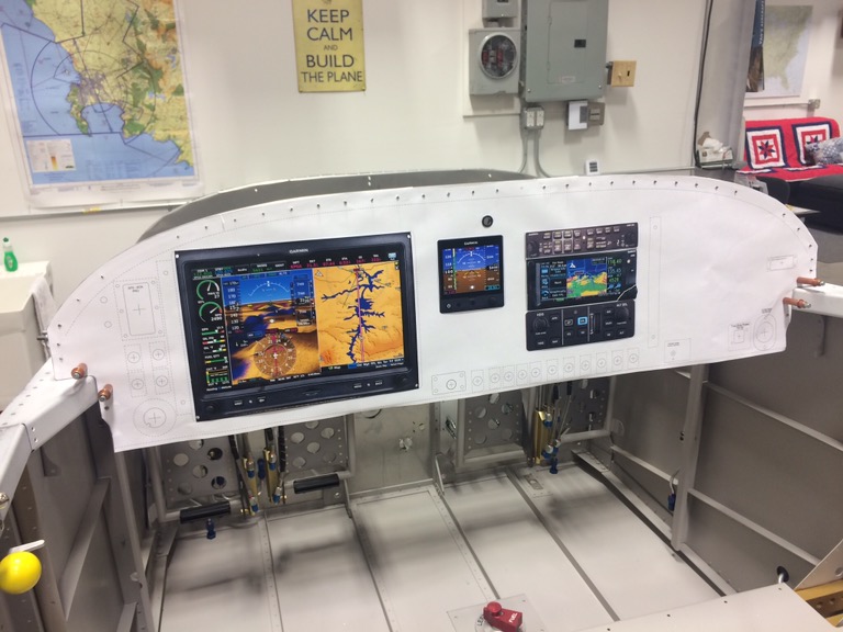
But I’m at the point now where I must make provisions on the instrument panel fo specific avionics, so it’s time to commit to avionics equipage and cut the panel. You can tell by the picture below that I’ve chosen Garmin avionics for just about everything except the Advanced Flight Systems AoA indicator.
I decided early on that I’d have the panel professionally cut so I needed to find a shop that could do the CAD layout and also had the ability to do CNC milling. There are lots of panel design and cutting providers on VAF, but I’d heard good things about Bill Morelli at Up North Aviation in Swanton, Vermont and decided to give him a try. I’m glad I did.
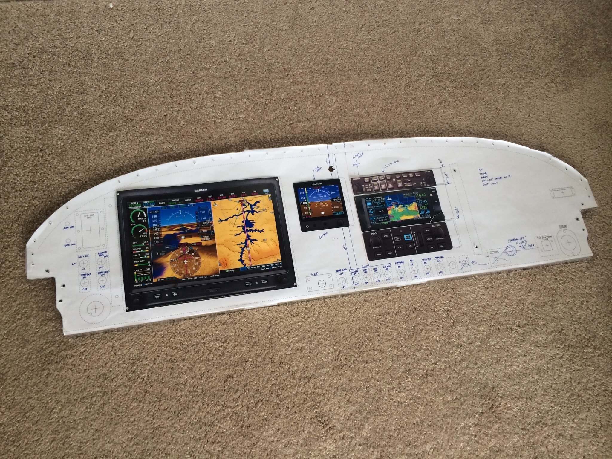
I already had a basic idea of what I wanted in the panel, so I gave my ideas to Bill and he came right back with full-size CAD layout PDFs based on my inputs. For most iterations I’d have Kinkos print out the PDF at full size, cut out the panel from the print, overlay it on the blank aluminum panel, then make adjustments that I sent back to Bill for a new CAD layout. Bill and I went through this cycle many times, and he was extremely patient with all the little tweaks I requested.
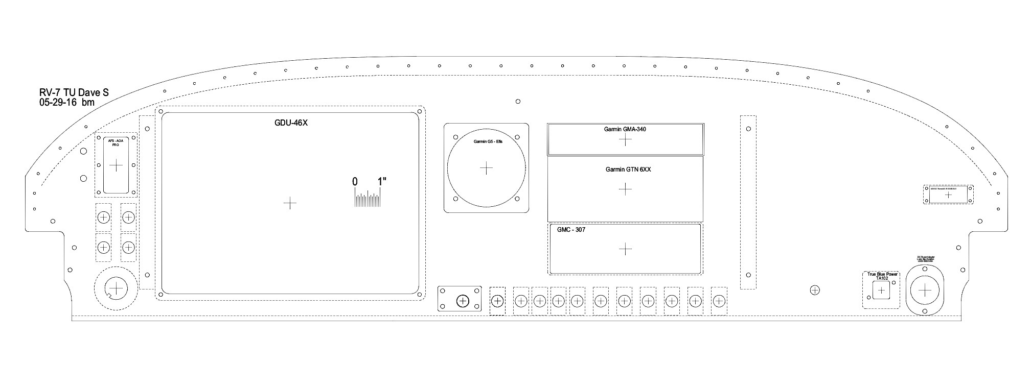
The above picture is Bill’s CAD rendering of my final design, and the picture below is the end result after Bill cut my panel.
I’m extremely pleased with how it came out!
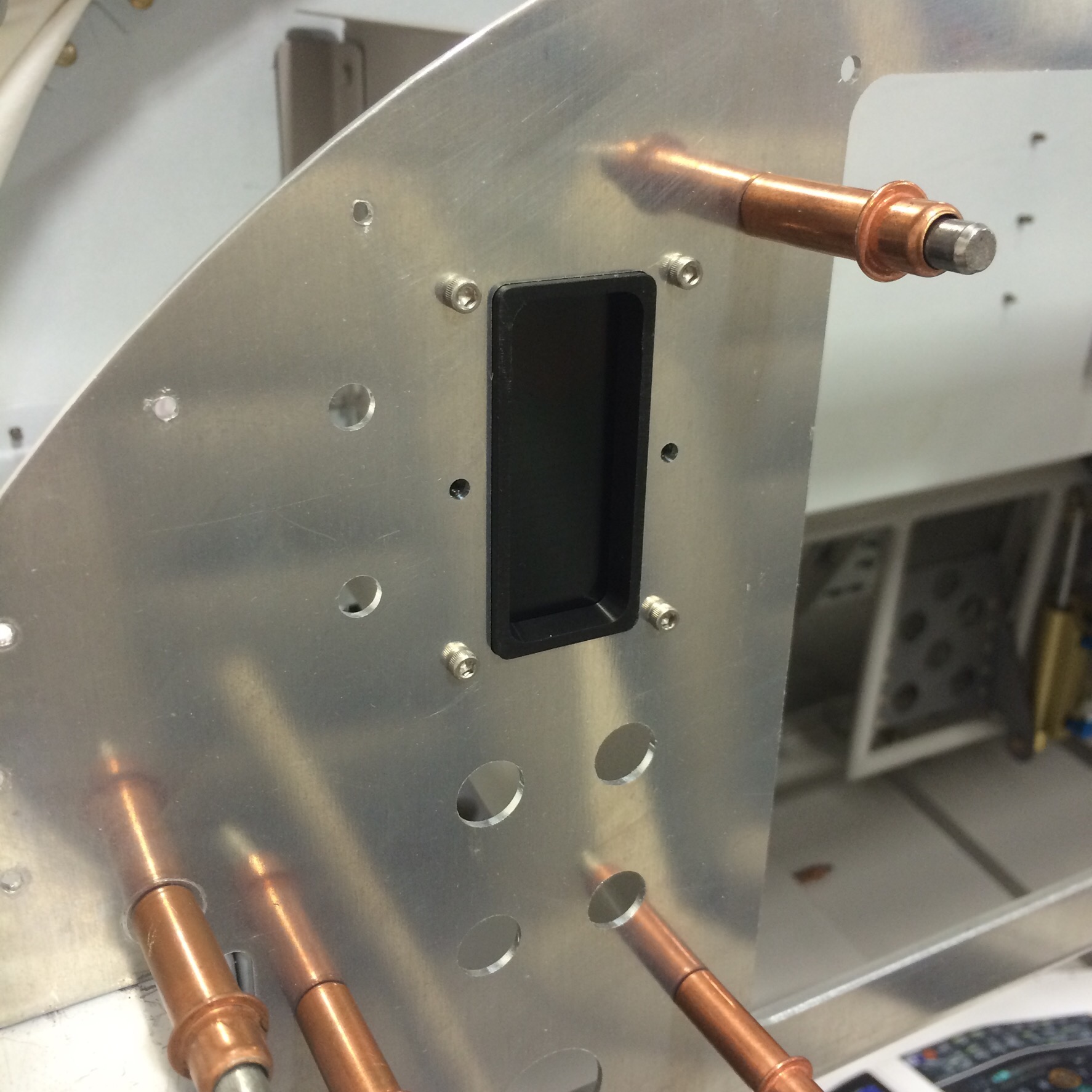
Here’s one example of the quality of Bill’s work. I pulled out the Advanced AoA display head and temporarily attached it to the panel. The fit is practically perfect!
With the panel cut, I’m warming up my frequent-flier rewards card in preparation for big avionics buys at Oshkosh…
The remainder of canopy work, mostly laying up the fiberglass front fairing, is on hold until warmer weather. So for the last two weeks I’ve been working on laying out and installing everything that needs to be on the firewall before the engine mount is permanently reattached.
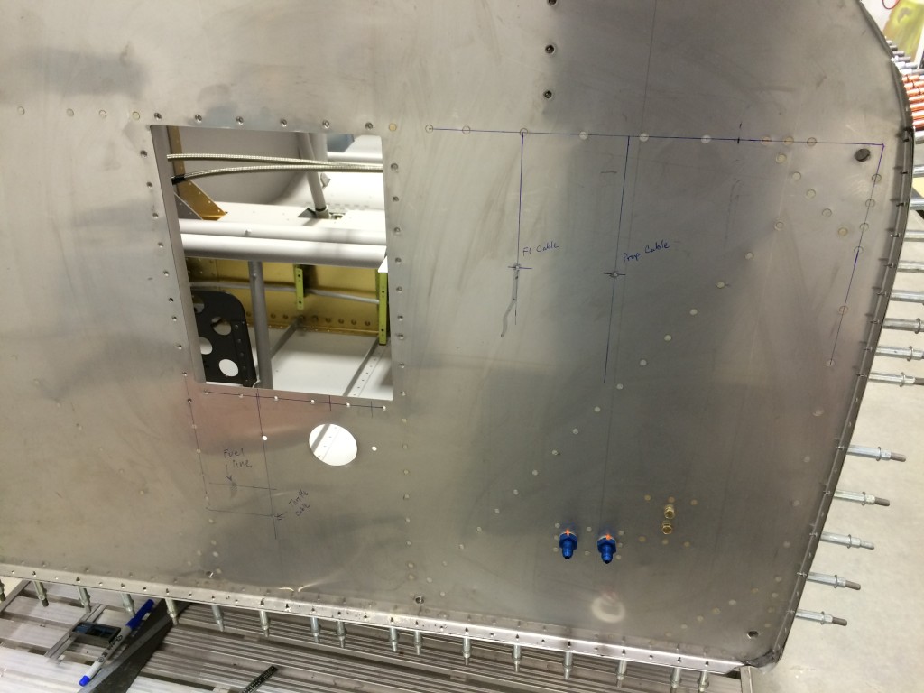
Throttle, mixture and prop cable penetrations laid out on firewall.
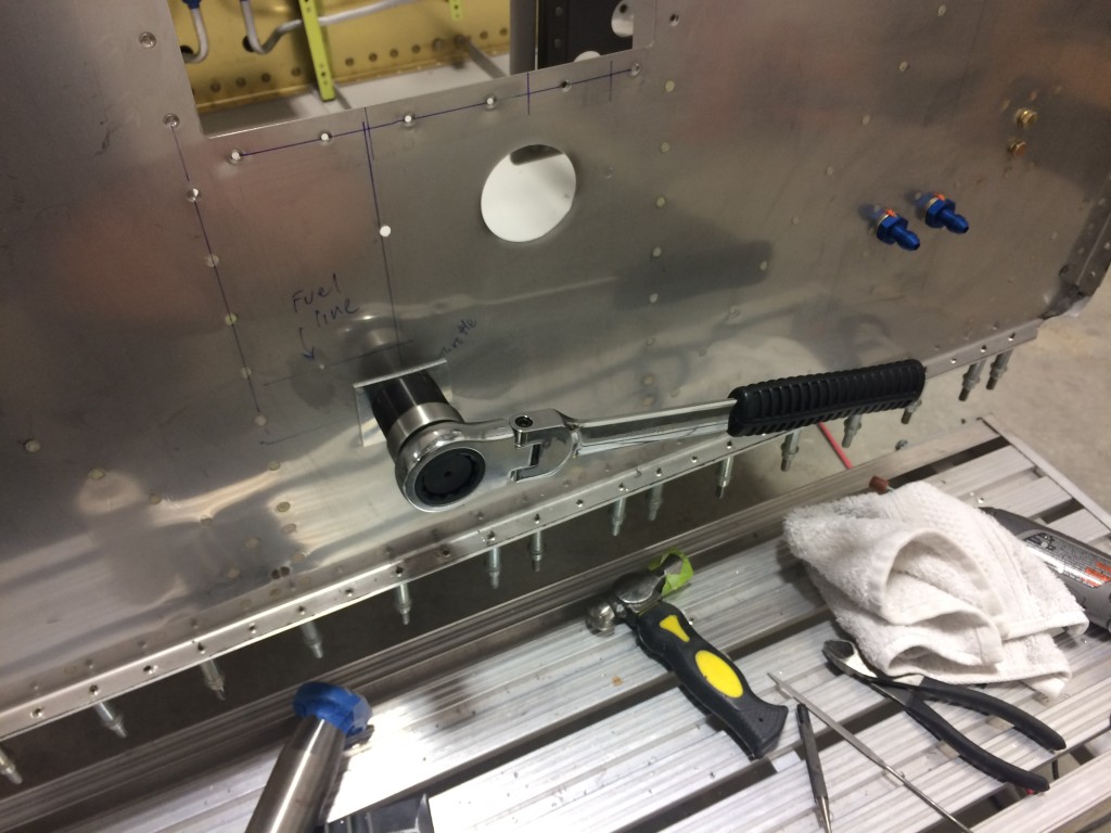
Cabin heat control box mounting holes cut, using my inexpensive Lowe’s knockout punch to cut the throttle cable penetration.
Not a super clean hole, but better than I could have done otherwise.
Fitting the fuel line penetration doubler.
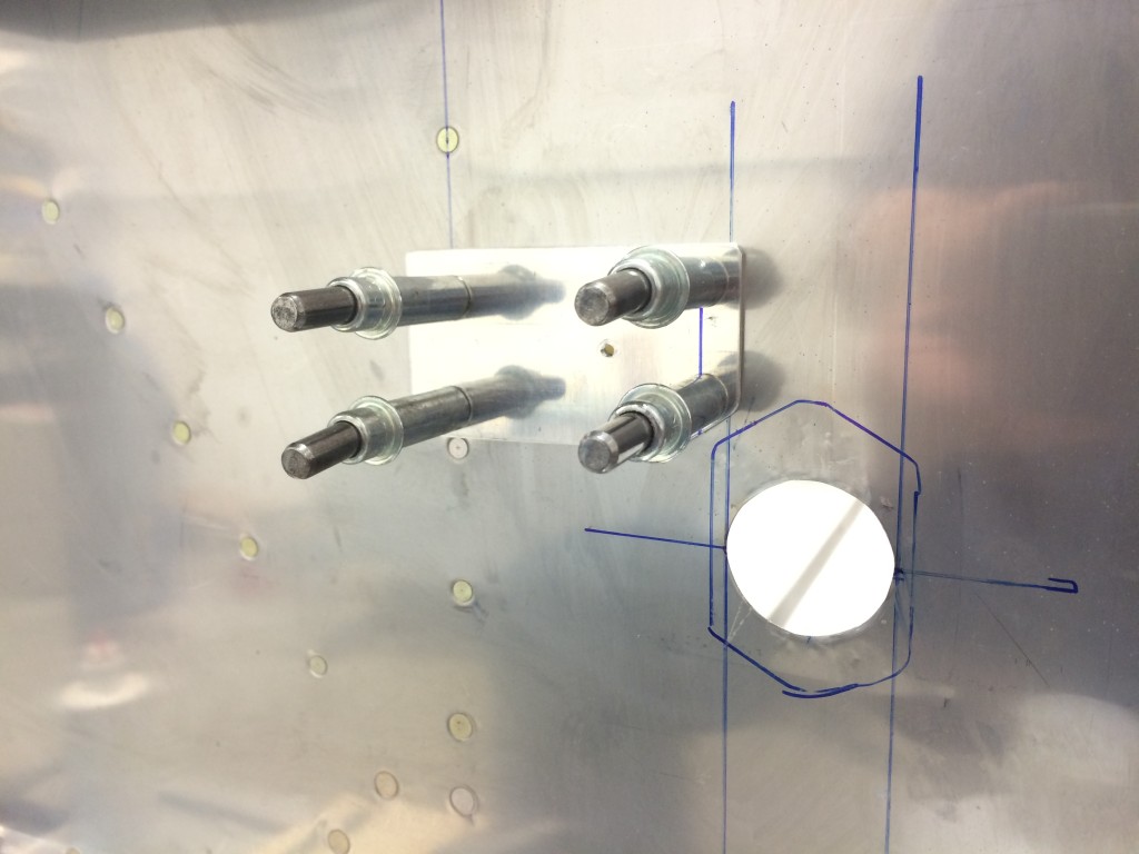
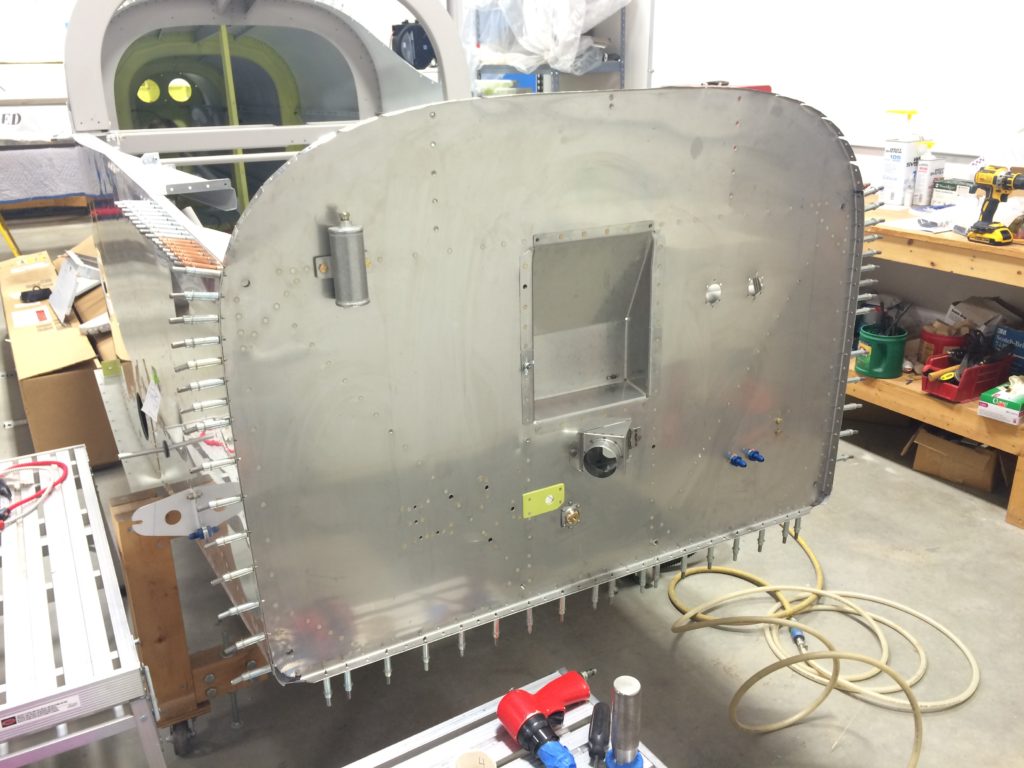
The oil filter cutout and battery box are in temporarily installed so I can begin laying out battery and starter contractor locations.
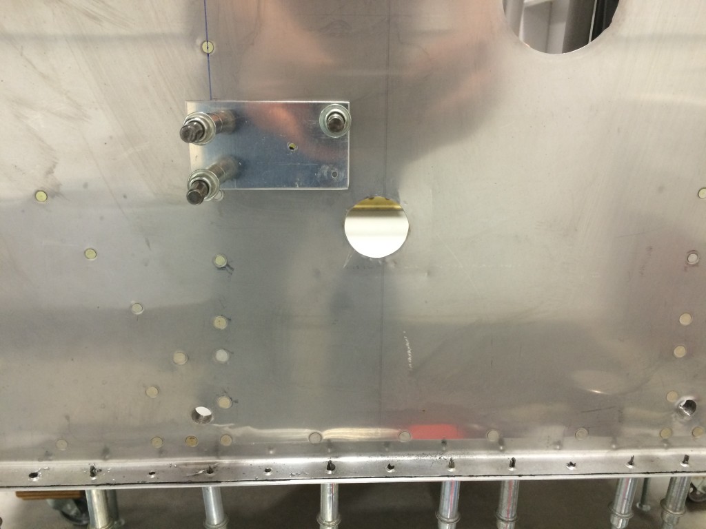
Fitting the starter/battery contactor doubler.
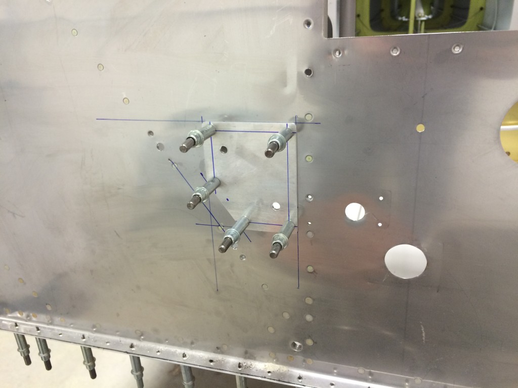
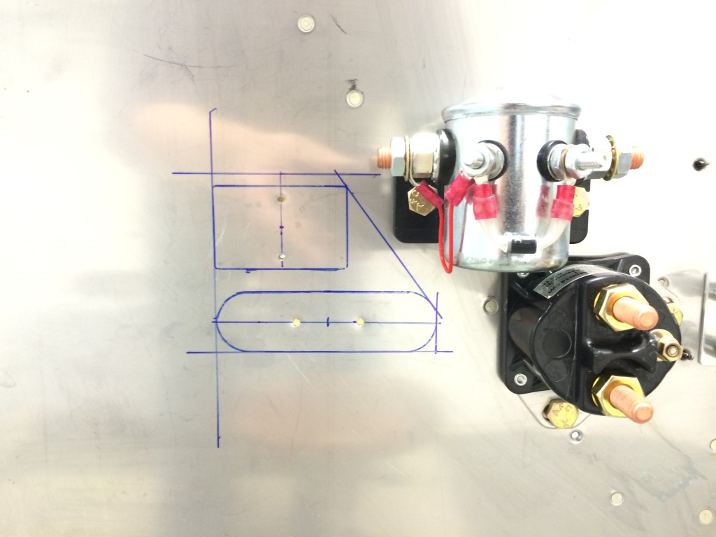
Battery and starter temp fitted, laying out location of ANL fuse holder and current-measuring shunt. The relative locations of the battery (top, silver) and starter (black, bottom) contactors was as close as I could get to Van’s plans locations while still accommodating the different style of starter contactor sold by B&C.
Doubler outline laid out, ready for fabrication.
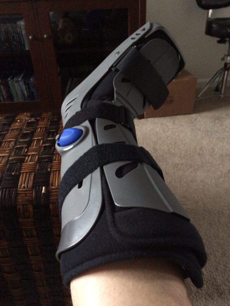
Mid-April – a running misstep led to a fractured ankle. No airplane work for a couple of weeks…this sucks.
Back to work in early May despite the booted ankle. With Ellen’s help, we got the contactor/fuse/shunt doublers and nutplates riveted to the firewall.
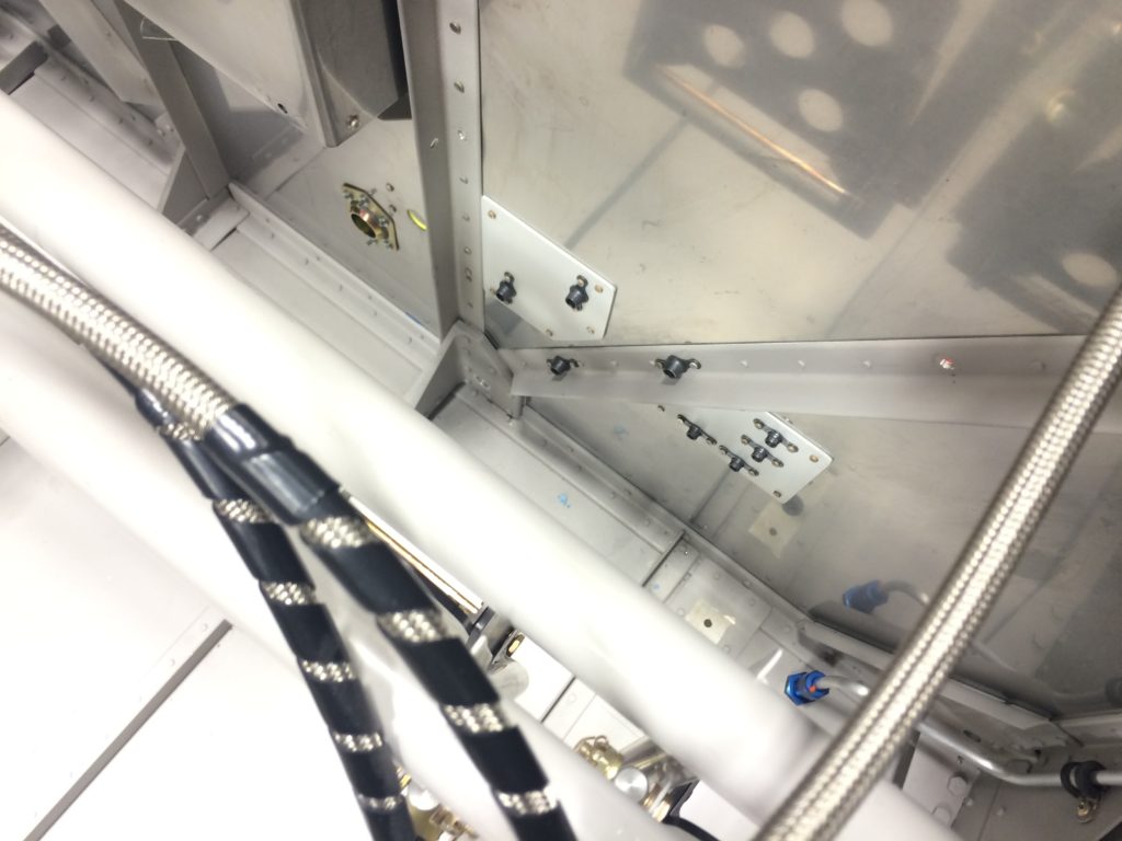
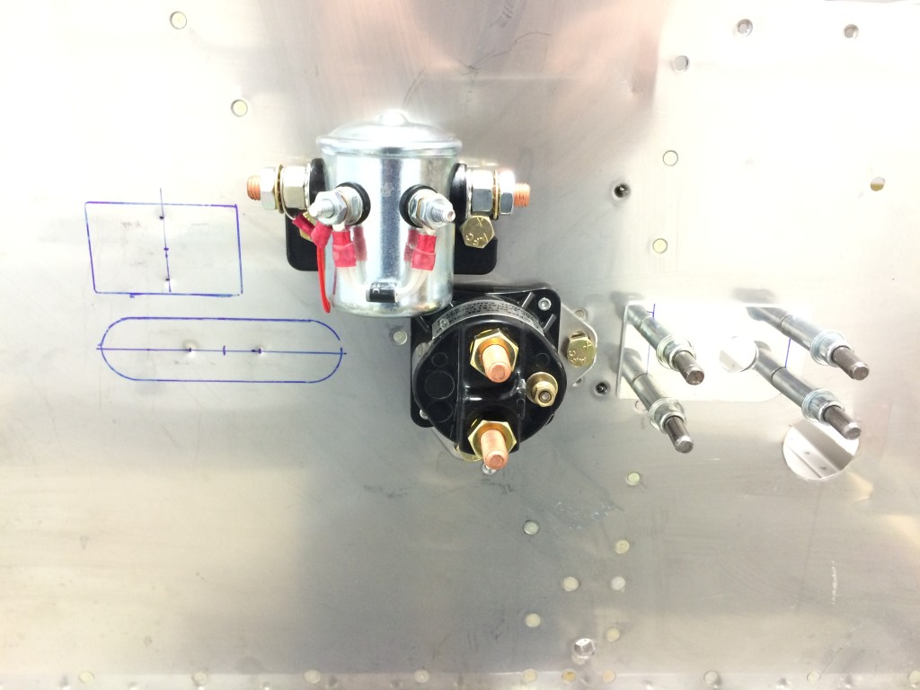
The result of an evening’s work – battery and starter contractor doublers and nutplates riveted to the firewall.
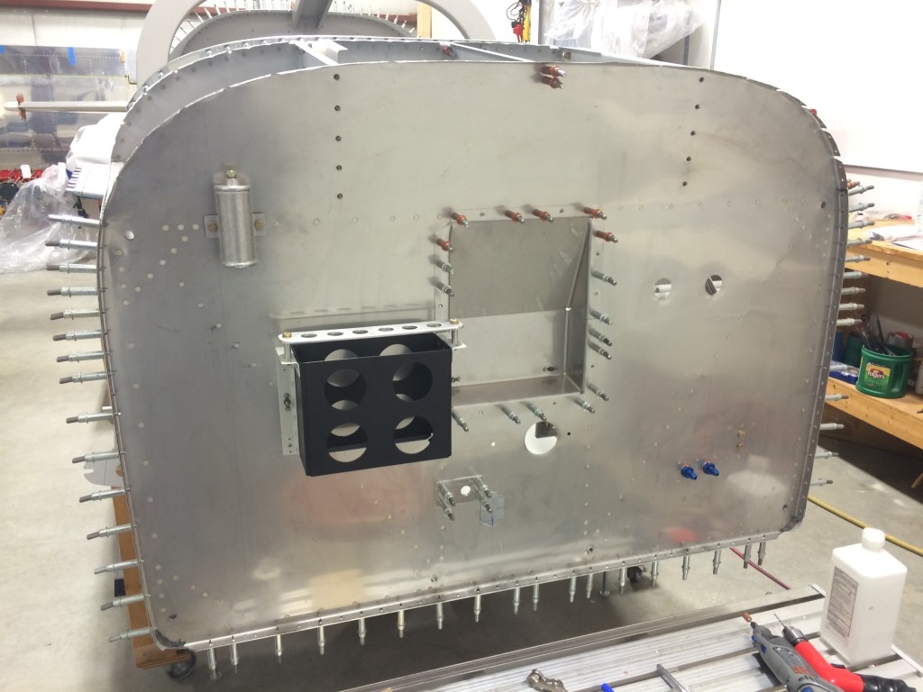
Everything (almost) is now riveted to the firewall, ready to install electrical components, battery box and control cable passthroughs.
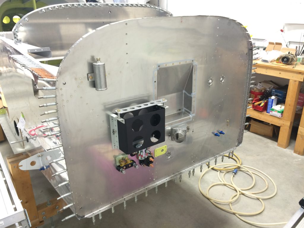
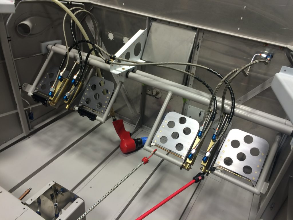
I was able to sneak away for a few hours and get most everything installed on the firewall. A few minutes of work for a nice little bit of visual progress.
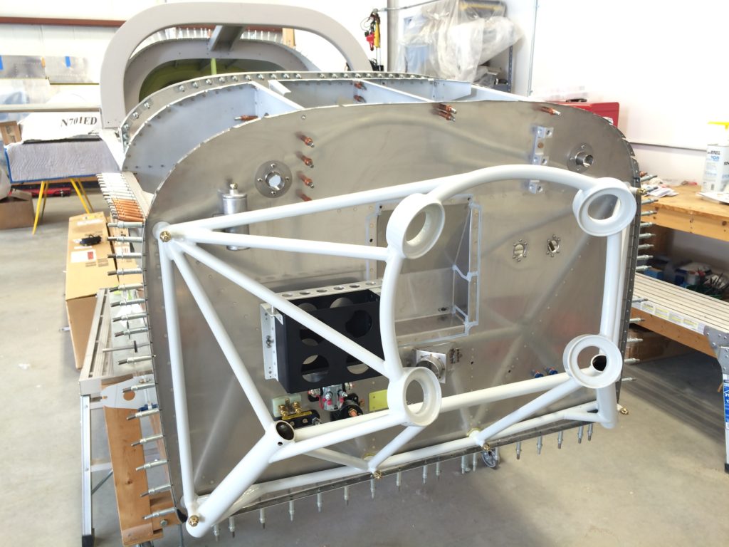
Fast forward a few days to finishing firewall prep and permanently reinstalling the engine mount. Ellen joined me at the hangar to help with fitting, bolting, torquing, hoisting and gear reinstallation. No more ankle boot, so moving around the airplane was a lot easier.
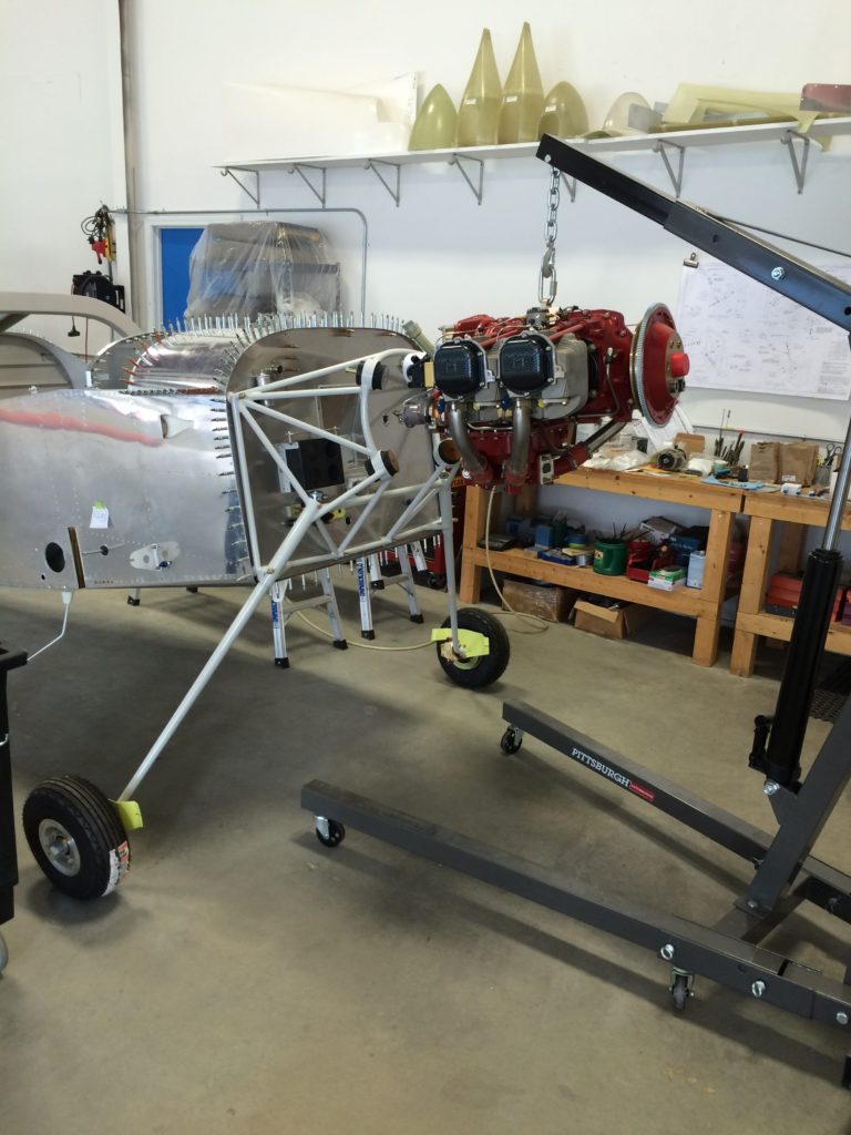
With the engine mount firmly and permanently attached, we hauled out the engine hoist and tow strap to get the fuselage high enough for the landing gear to be reinstalled.
…and the fuselage is back on the gear for good. It’s engine hangin’ time!
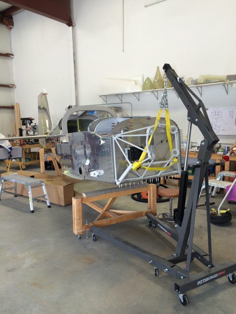
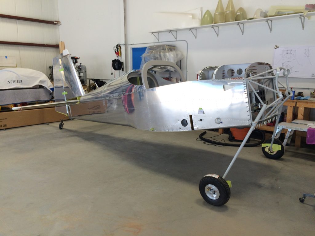
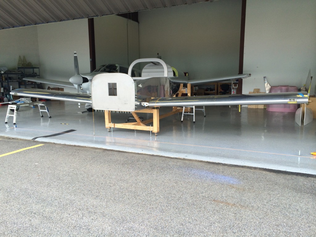
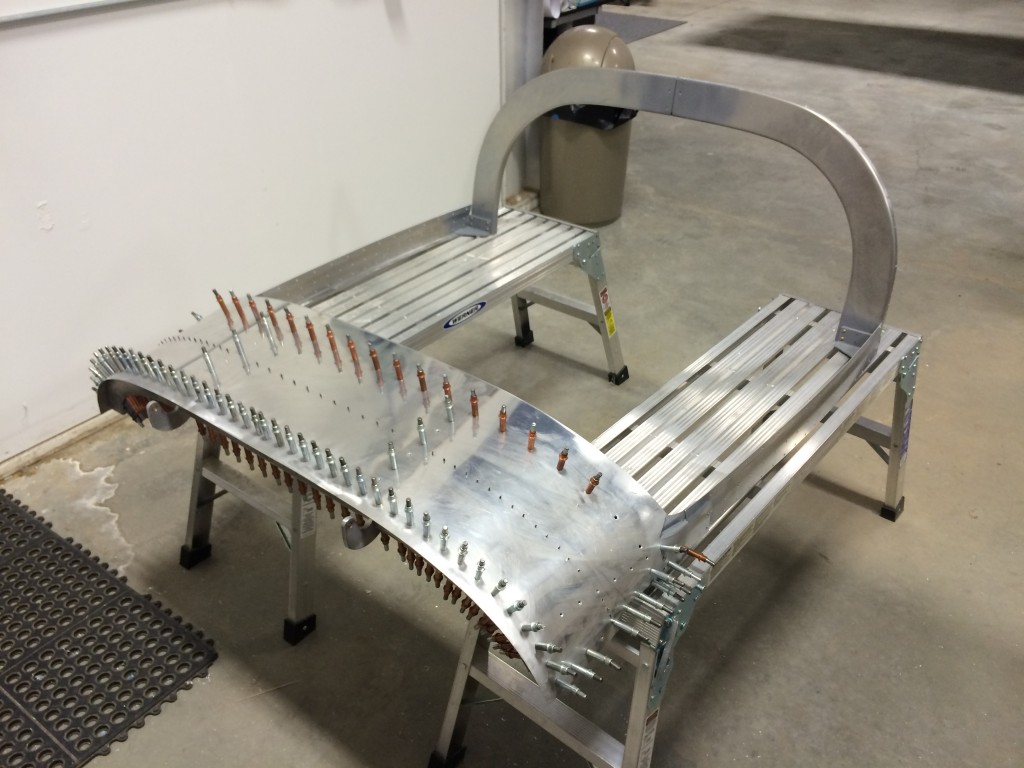
Back when we put all the small fuselage pieces together into one big pice, I built a spiffy rolling stand to hold the fuselage so I could be moved easily around our small garage. It was adapted from plans provided by Lars Pedersen on VAF.
It served its purpose well, and we’ve used it as we attached wings and tail, fitted the canopy, and prepped the interior and firewall.
But now that the landing gear is on the fuselage (hopefully) for good, it’s time to pass the stand to someone else who can put it to good use.
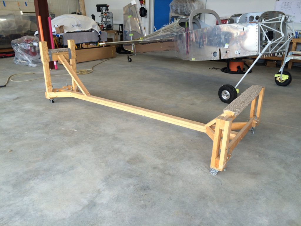
It’ll definitely fit an RV-6, -7, -8 or -9 fuselage, and maybe a -10 as well but I haven’t measured it to be sure.
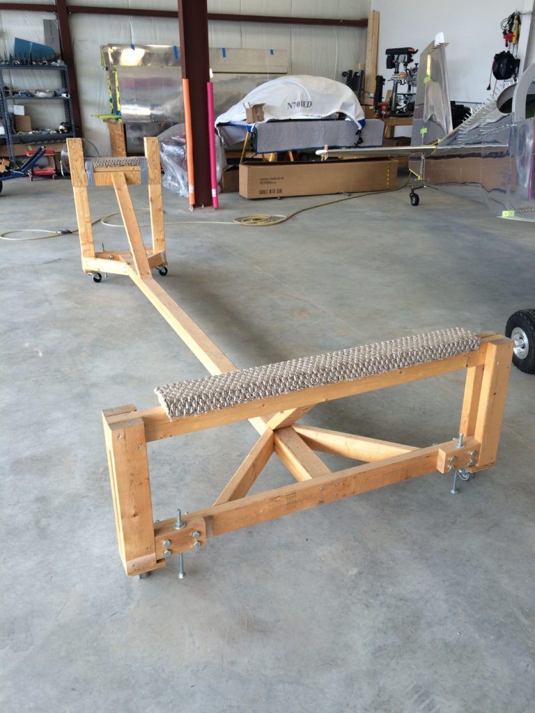
I’ve added some little jackscrew thingies on each corner to make it easier to level the fuselage when/if needed.
It’s free to anyone who will come to the Nashua NH airport and pick it up. All I ask is your promise that you’ll put it to good use on your RV project, and that you’ll pass it on to another builder when you’re done. If you’re interested, use the “leave a reply” link on this post to send me a message and I’ll get in touch with you.
Back before we moved the project to KASH, I temporarily installed the engine mount and landing gear so we could move the fuselage more easily. Because it’s almost time to permanently reinstall both items, the brakes need to be installed before the airplane is on the landing gear for good.
This is probably the most poorly documented part of the project so far in Van’s instructions, in part because they reference Cleveland wheels and brakes – and Van’s delivered MATCO wheels and brakes with my kit. I don’t know why and I don’t think I asked for them, but whatever.
One of the big differences between Cleveland and MATCO wheels is MATCO’s use of sealed wheel bearings rather than Cleveland’s unsealed versions. Bearings with an integrated dust seal last longer, but they’re harder to pack with grease – I couldn’t use my spiffy Lisle bearing packer device which pushes grease through the bearings. Instead, I had to put on rubber gloves and pack them by hand by shoving grease into every available nook and cranny.
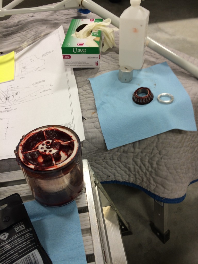
Yes, it’s a messy job.
One other thing to note about MATCO wheels is that the bearing races are milled into the wheels themselves, and the bearings don’t rotate around the axle. Therefore, it’s important to torque the wheel nuts sufficiently to provide enough friction to keep the bearings from rotating.
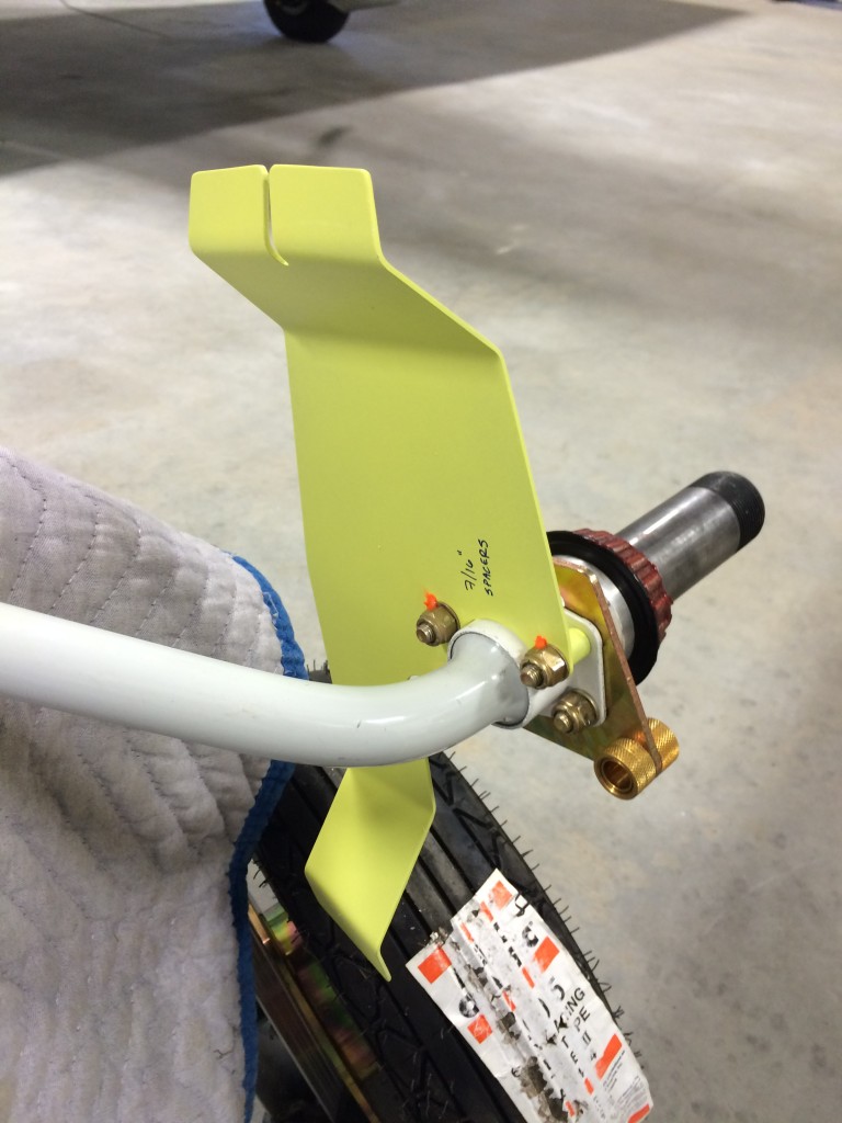
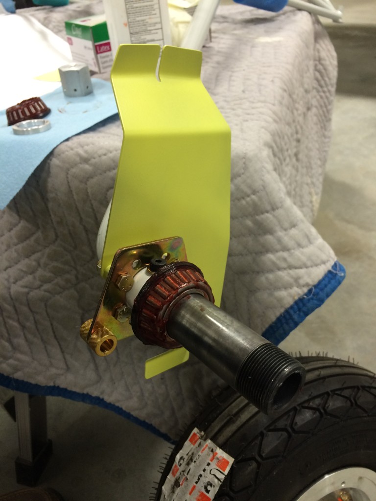
The drawings are also unclear about how the brake caliper and wheel pant support brackets are arranged on the axle. So for those of you who are scratching your heads over this as I did, here are a couple of pictures that show how the assembly goes together. In both pictures the large portion of the wheel pant bracket pointing up, is oriented forward with respect to the airplane.
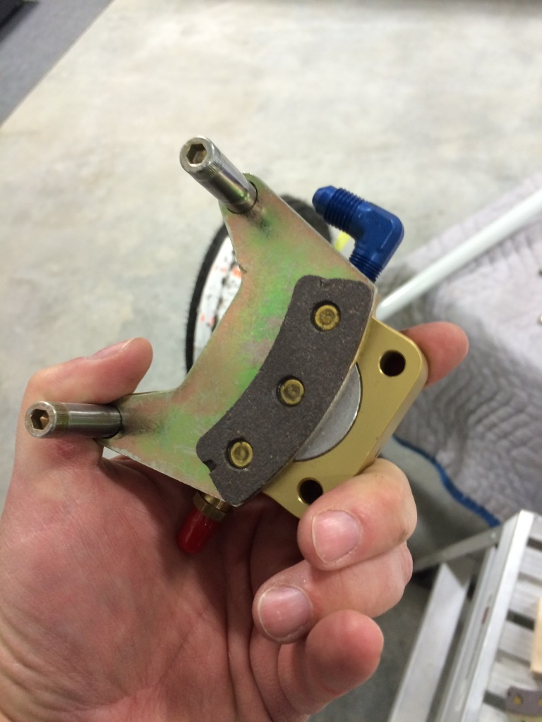
Another thing that wasn’t clear was how to get the brake caliper apart to fit it over the brake disc. It’s actually easy, there are two bolts on the back of the caliper that are removed, then it’s an easy matter to install the wheel, torque the wheel nut, then slip the caliper back in place and reinstall/torque the caliper bolts.
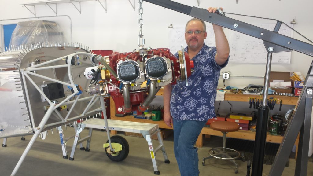
Over the last couple of weeks the heart of the Mighty RV arrived at the ThermosWorks. If you recall from past posts, I engaged Tim Hess at Unlimited Aero Engines to build, flow-match, balance and test a Superior XP-360 engine.
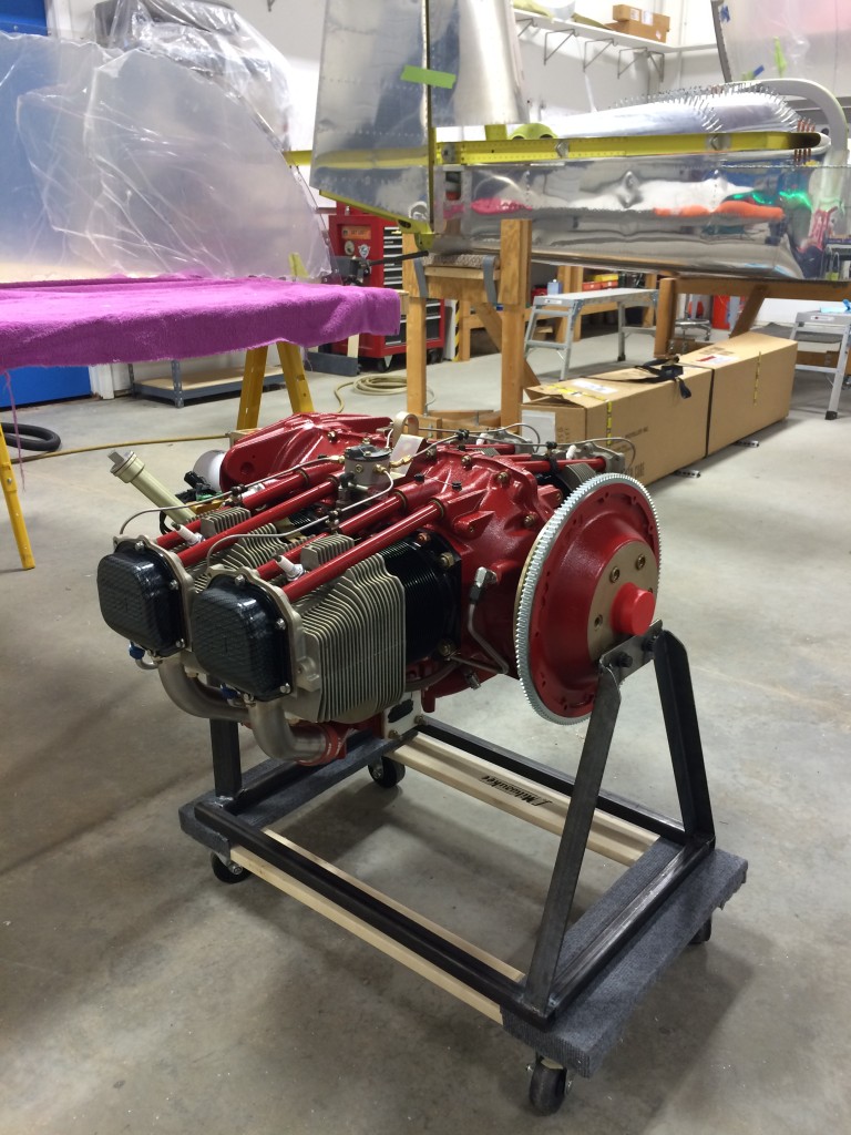
In mid-February, Tim delivered this work of art to the hangar. It’s been test-run on a dyne stand and produces 184.9 horsepower. The rocker box covers have been hydro-dipped in a carbon fiber weave pattern – Tim’s idea, and they look great…
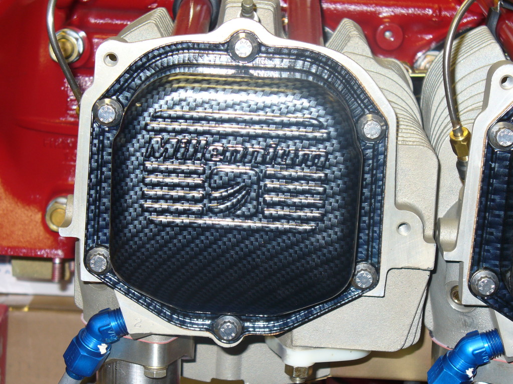
In fact, they look so nice that I’ll replace them with stock covers until the cowl is fitted!
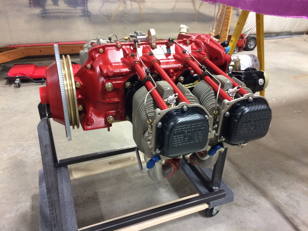
The choice of color was Ellen’s, and as usual, she was spot on. The engine is gorgeous, and my only concern is keeping it looking this way once it’s in the airplane.
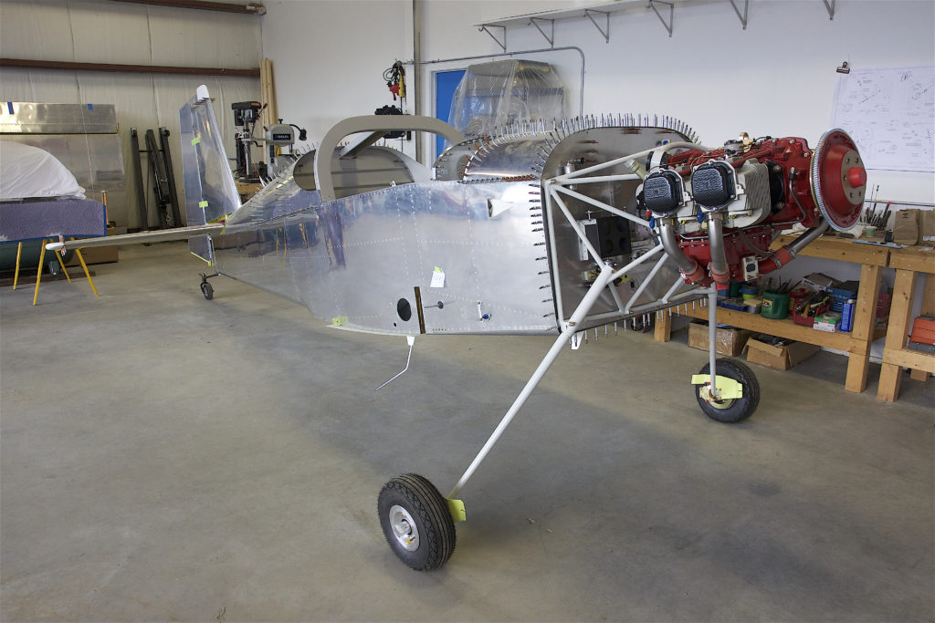
The other chambers of the Mighty RV’s heart were drop-shipped from Piqua, Ohio by the good folks at Hartzell Propeller…
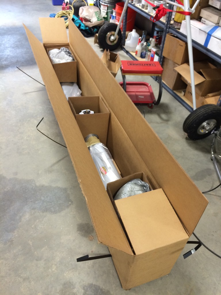
Not much to see in the box, and the prop will stay there for awhile until it’s time to put it on the engine.
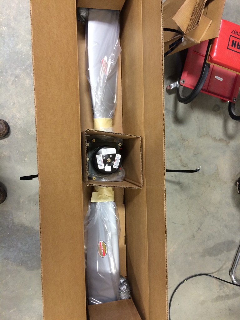
It’s been a long haul to get to this point, and with the delivery of the engine and prop, everything has suddenly become a lot more real…it’s easier to envision this assemblage of aluminum, steel, plastic, blood, sweat and tears as an airplane.
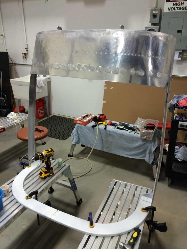
With the plexiglass canopy parts mostly under control, I’ve moved back to finishing the canopy frame and skins.
First off, I finished match-drilling the rear canopy frame. Nothing too difficult here.
I pulled the frame off the fuselage then deburred, countersunk, primed and riveted everything together. Then, I started on the canopy lift strut attach brackets.
The forward attach points require a lot of tweaking and fitting to fit inside the forward canopy frame. Once match-drilled, they’re tapped to accommodate #10 screws that keep them in place on the frame, and also for the large “knob” that provides an attachment point for the lift struts.
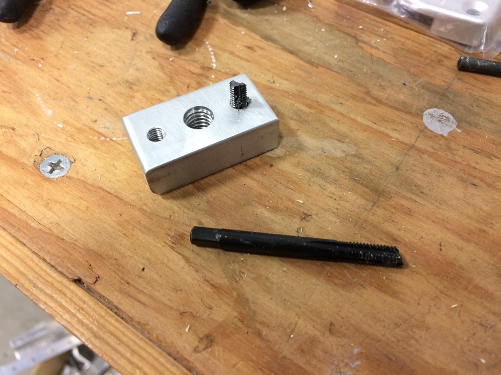
This quality Vermont American tap failed on its second use. I did a little research on where VA’s tools are made, and it seems like their name should really be Vermont Chinese, or Guangdong German, or something that more accurately depicts where the company really resides.
Not that I mind buying cheap Chinese shit tools…I go straight to Harbor Freight when I need a tool that I’m gonna intentionally tear up or modify, only has to last for a few uses, or most importantly, is something that my life won’t depend on.
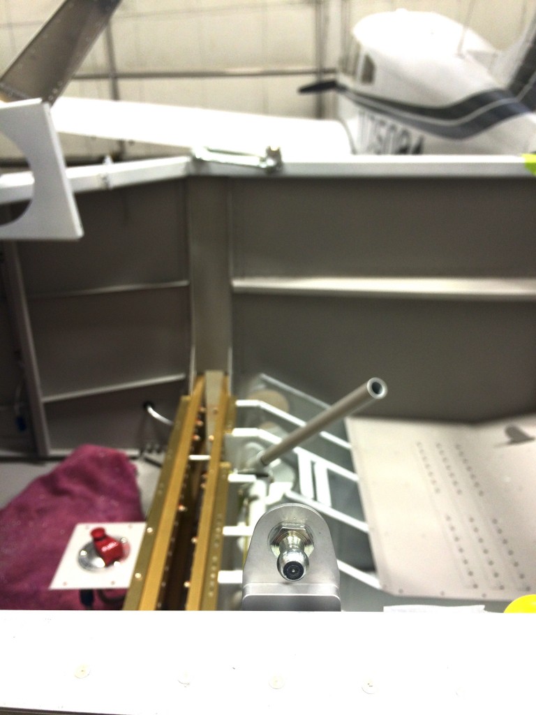
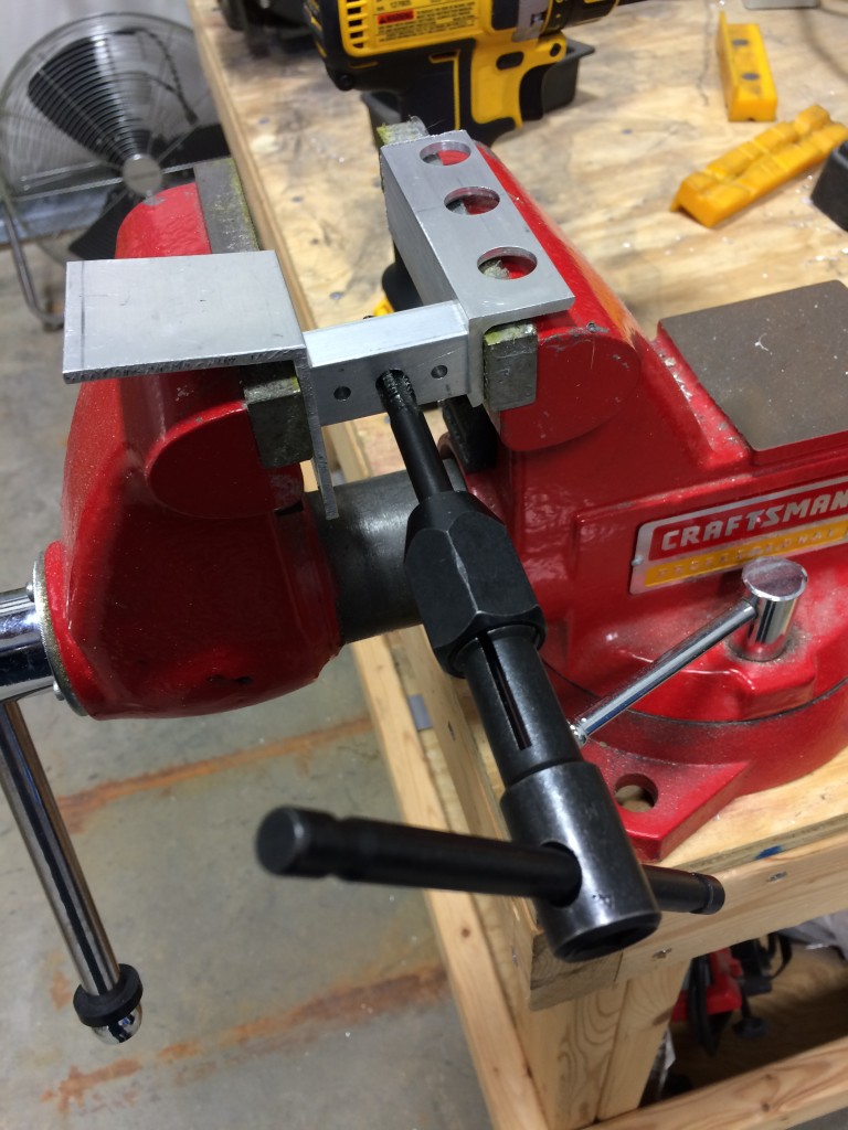
I’ve been waiting a long time to use these custom-machined canopy strut mounts from Rich Mileika at Machine, Inc. Not only did they save a lot of fabricating time, they look really cool too.
Locating the right position for these mounts was the easy part; getting them screwed into place was harder. Once the mounts were match-drilled to the canopy rails for #10 screws, I had to get up, under and behind the canopy rails to get the locknuts in place.
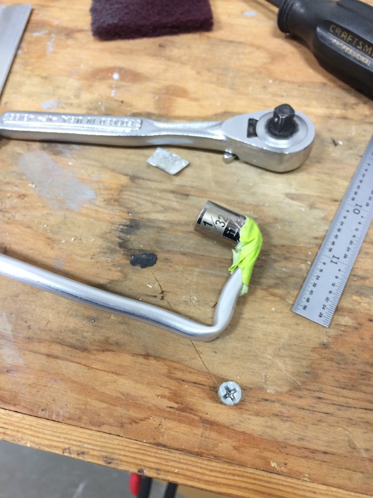
I didn’t have any wrenches that would get into this spot, so I improvised…I took a cheap 11/32″ socket, hammered it onto a piece of 1/4″ aluminum fuel tubing, and bent the tube such that I could get the socket around the canopy rail. As ugly as it is, it worked like a champ. After I used it to get the mounts installed, I pulled the socket off and reattached it with JB Weld – probably won’t be the last time I’ll need to use this device.
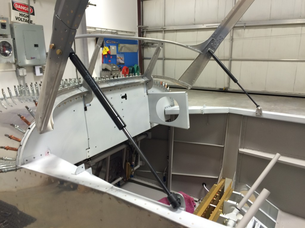
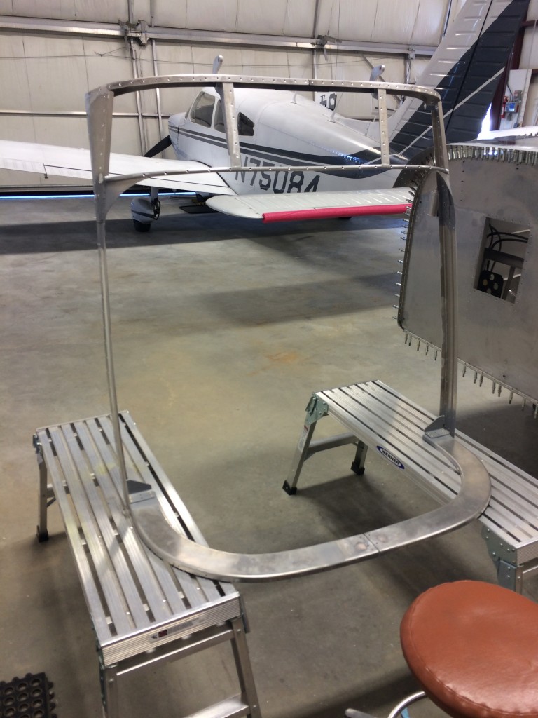
Here’s the canopy frame with the lift struts attached. Cool.
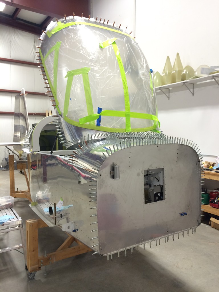
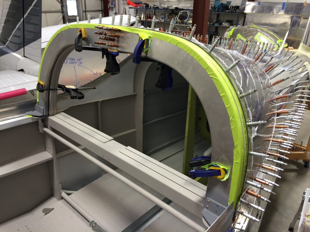
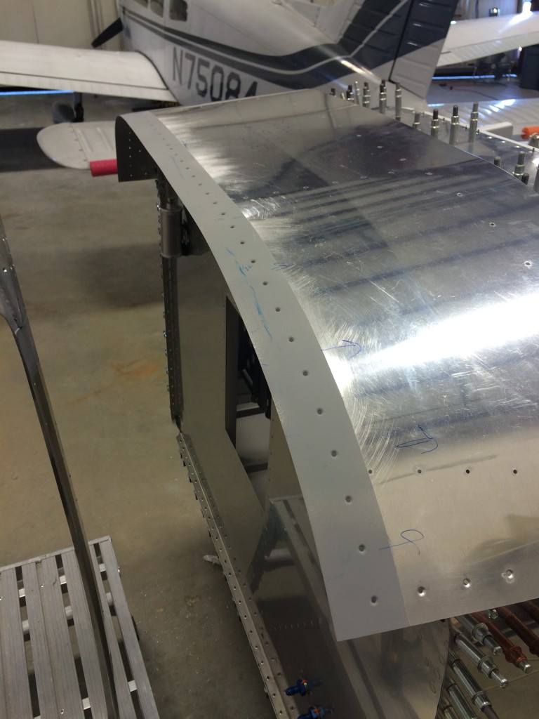
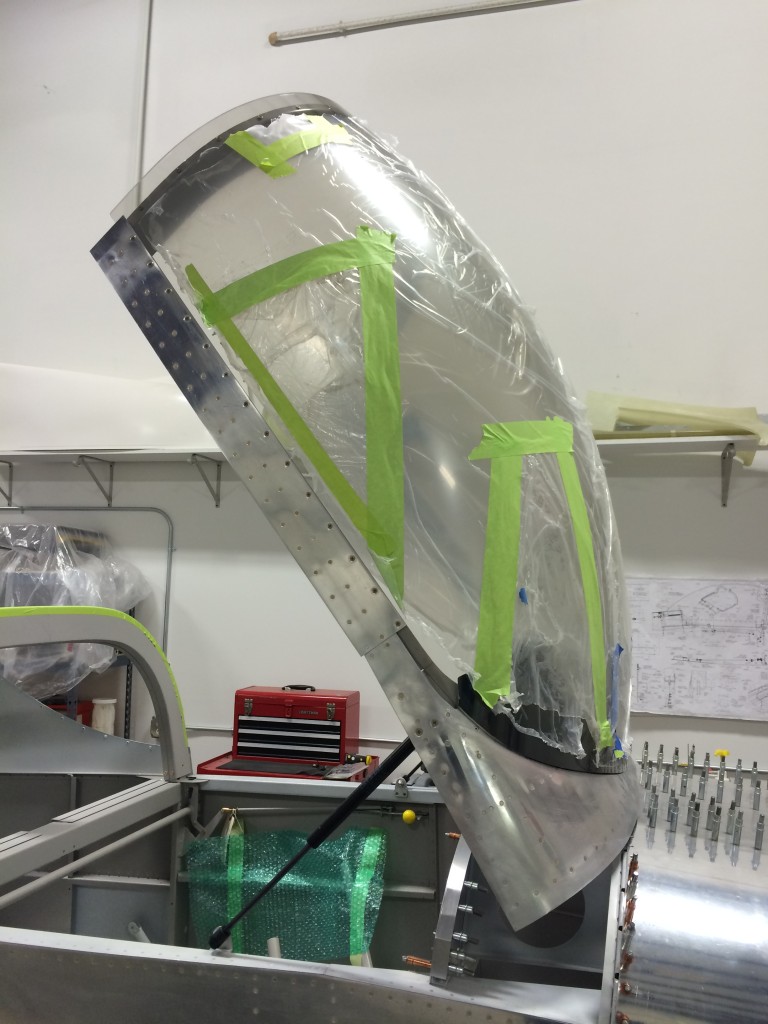
I put the canopy back on the frame…it’s time to start fitting the side skirts.
The challenge here is getting the skirts clamped in place. Some builders have made some really spiffy clamps out of aluminum C-channel to slip under the skins and hold them in place, but I didn’t have the patience to do that.
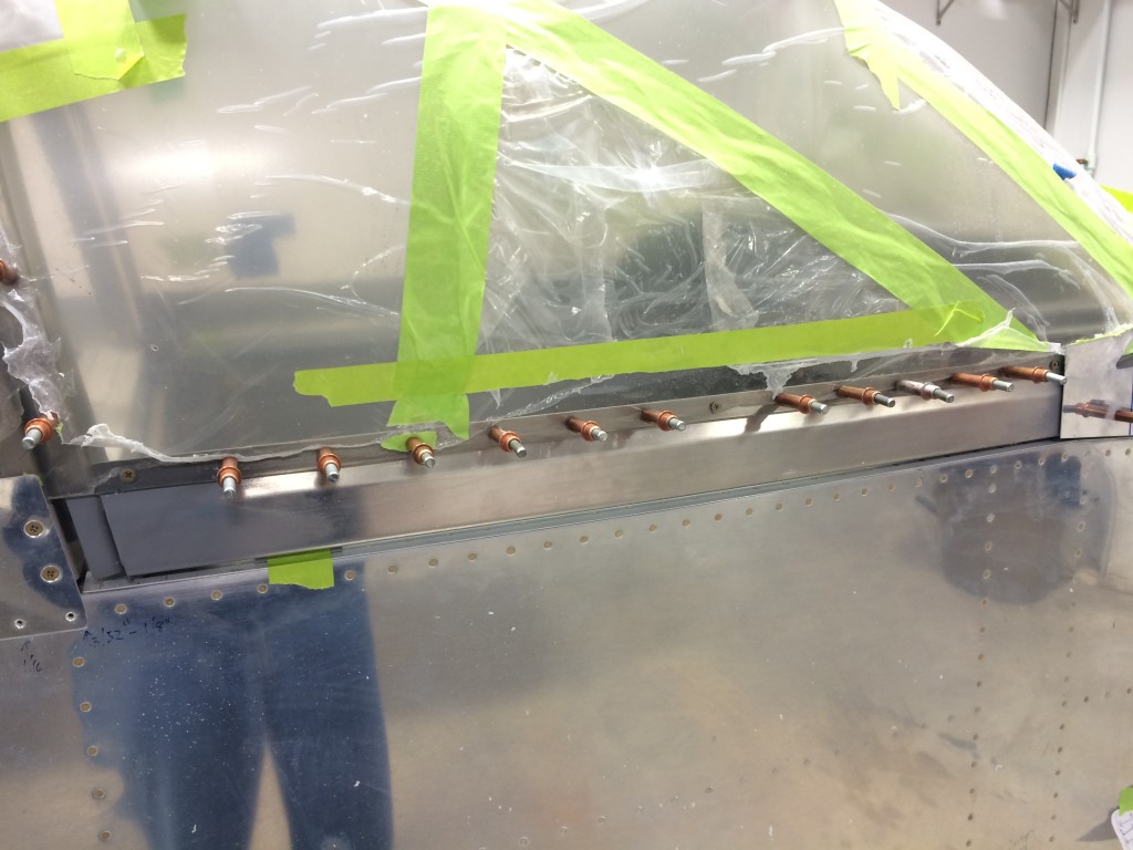
Instead, I just used some 3M two-sided tape to hold the skirts in the correct position until I could raise the canopy and clamp them with regular Pony clamps. In the pic above you can see that I’ve already laid out and pre-drilled the side skirt rivet holes.
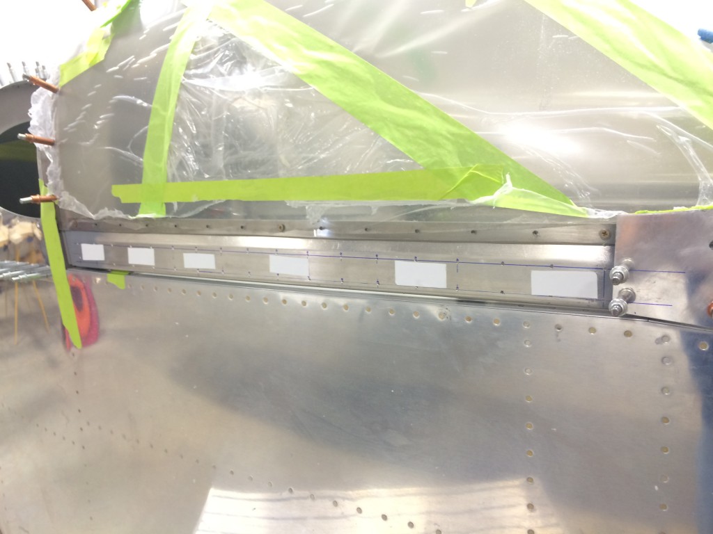
Lookin’ good prior to drilling…
And after several minutes sitting inside the closed canopy (cool!) with an air drill, the side skirts were match-drilled to the frame. Not much left at this point except to countersink the frame holes and debur/dimple the skirts.
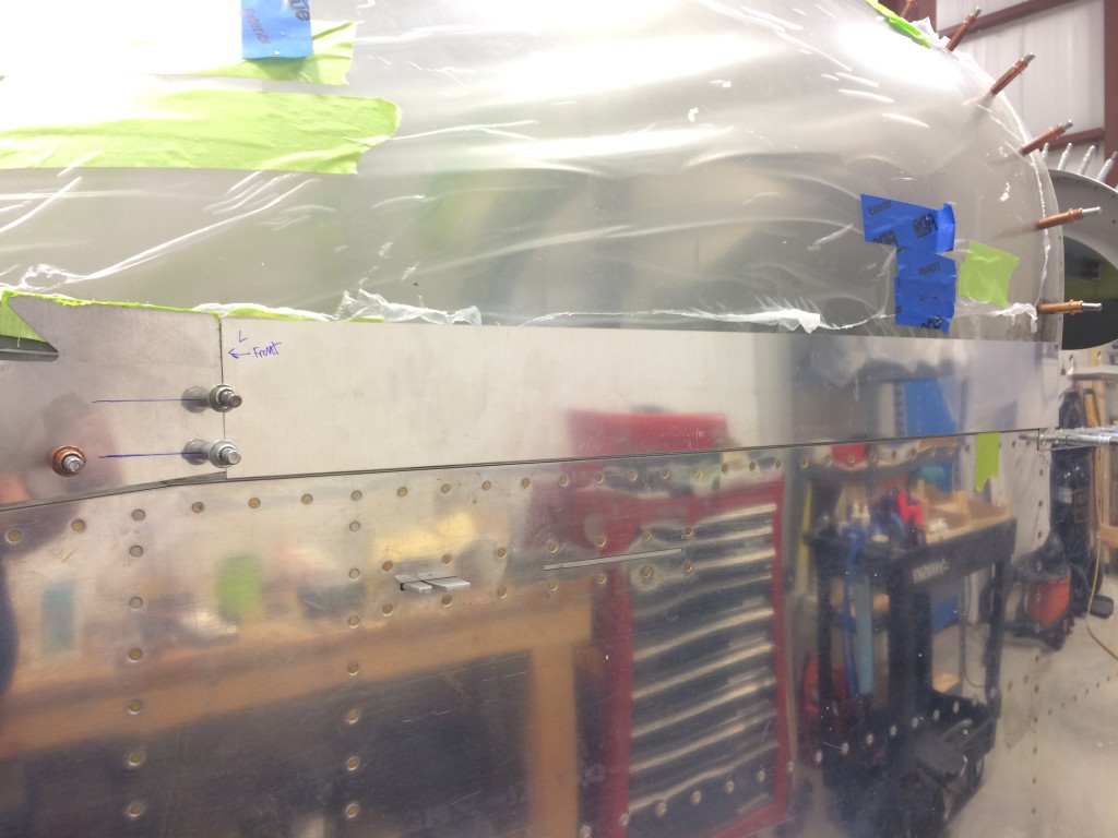
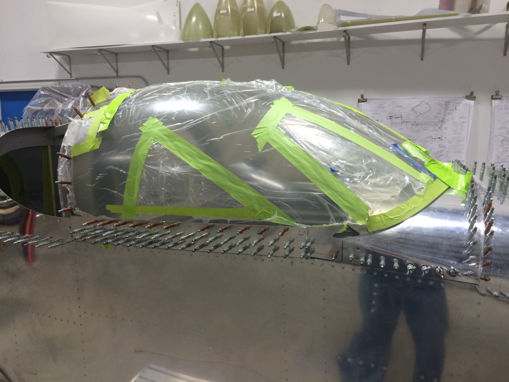
One of the things I wasn’t too happy about was the fit of the forward canopy skin to the forward fuselage skin – they just didn’t quite line up.
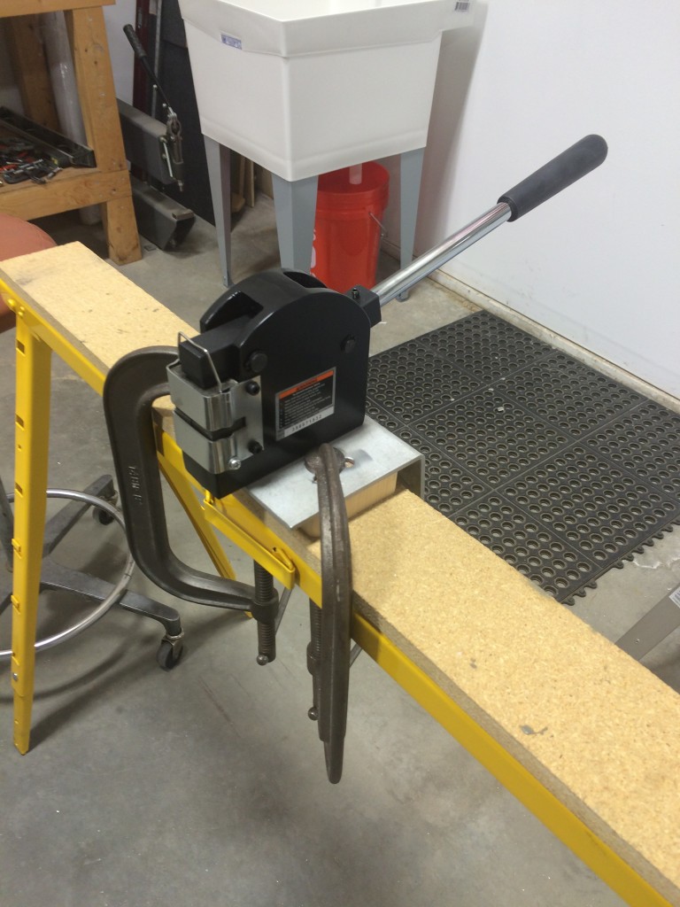
As I tend to do, I threw money at the problem. I made a trip to Harbor Freight and bought a metal shrinking/stretching tool set. After practicing on some scrap sheet metal, I used the metal shrinker on the leading edge of the canopy skin.
The results were better than I expected…the metal shrinker really closed up some of the gaps between the canopy skin and forward fuse. Unfortunately, I didn’t get a picture of the fit with the canopy installed, so you’ll just have to trust me.
One slight downside to the metal shrinker is that it leaves small toothmarks on the metal when it’s used – but a scotchbrite pad on the die grinder made quick work of them.
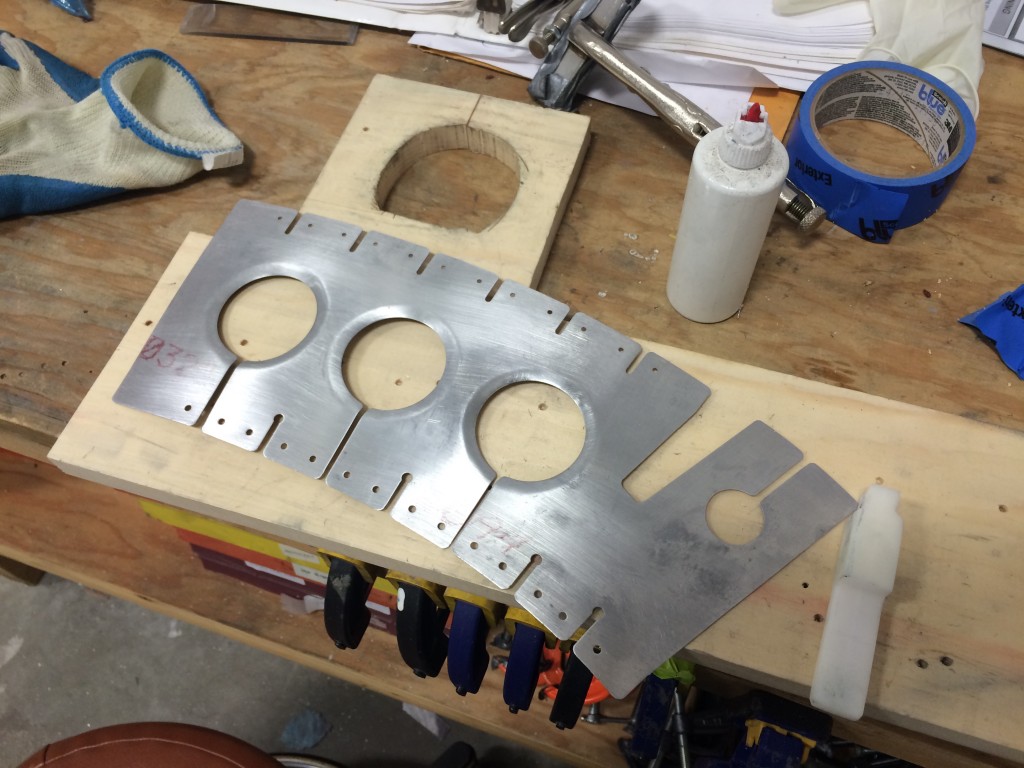
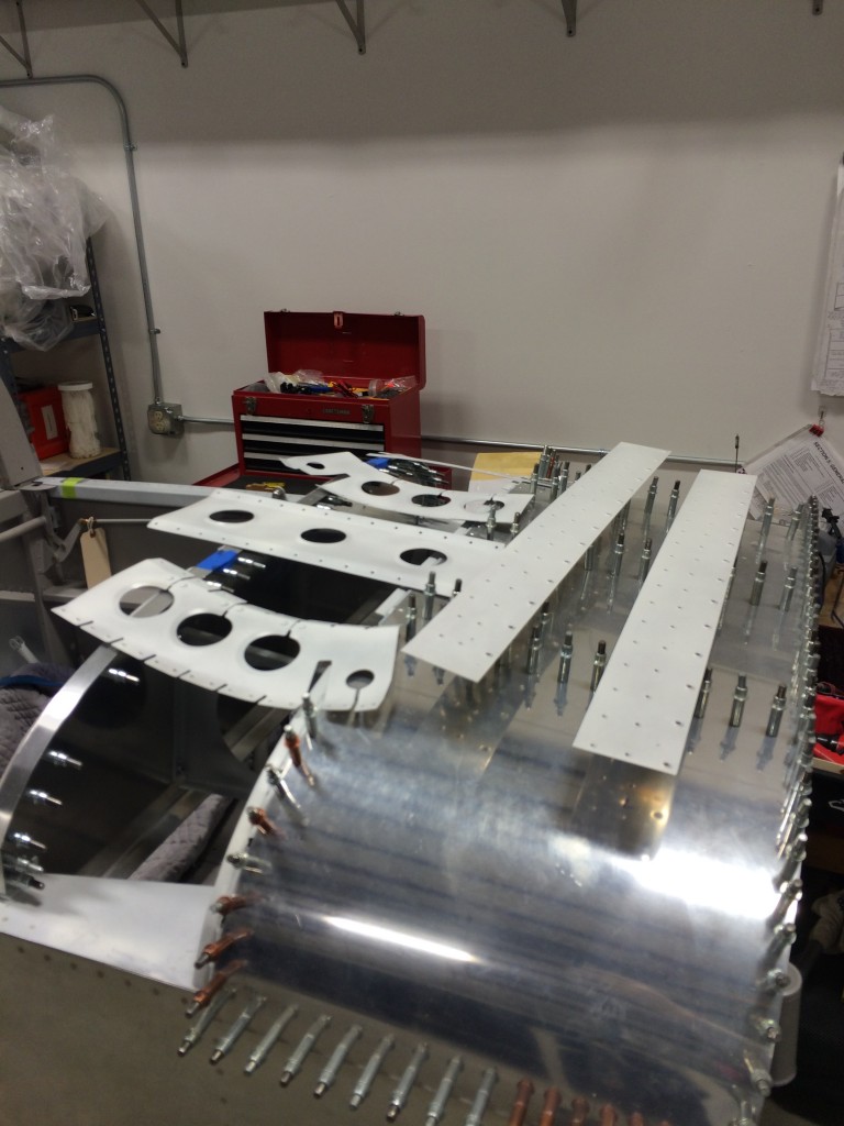
Like most tip-up builders, I chose to install the optional canopy reinforcement kit. Otherwise the canopy frame is pretty floppy even when the canopy bubble is installed. There are a lot of holes and slots that need deburring, fortunately there really isn’t much more of this to do on the project.
The plans call for the three large lightening holes to be “flanged”, or have the edges of the holes bent slightly to make the metal stiffer. There are lots of way to do this, and I chose the old-fashioned way – a piece of delrin with a slot cut into it, which is used to bend the edge as it’s slid around the inside of the hole.
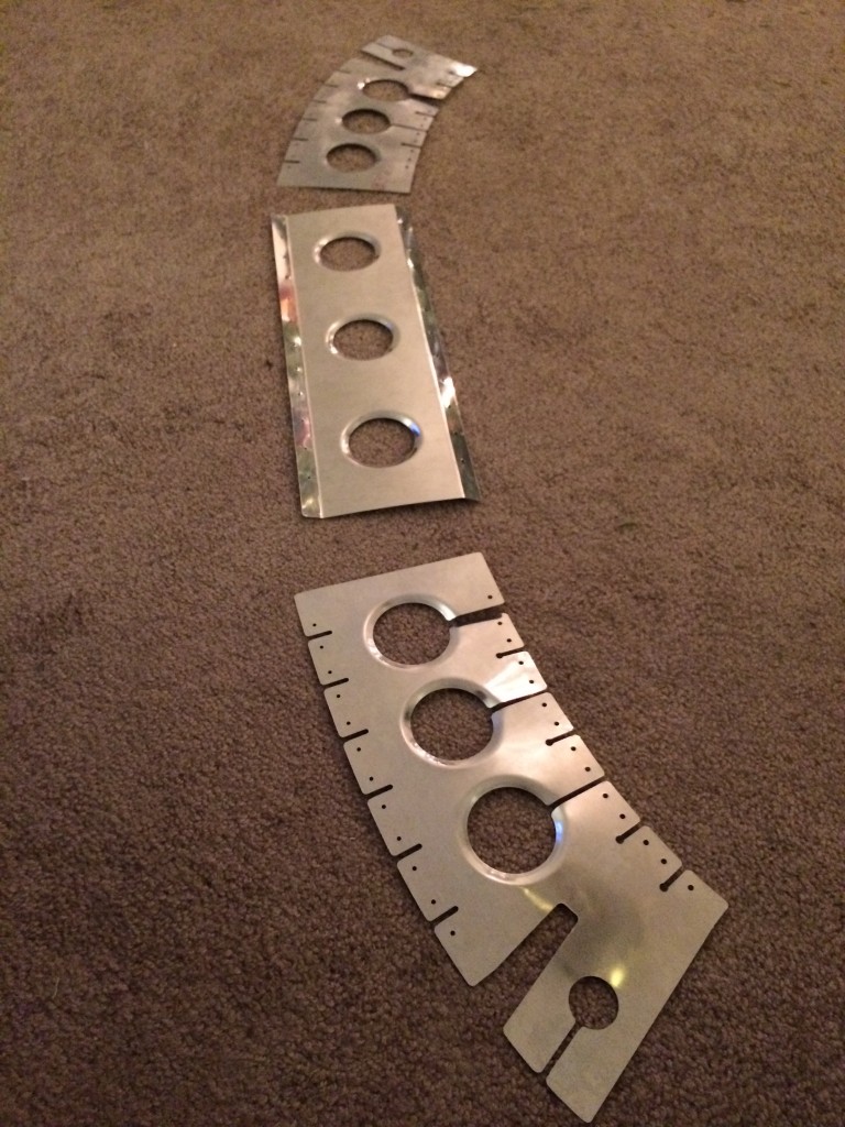
It’s a pain, because several passes are required to get a good bend – but in the end, the flanges came out great.
Here are the stiffeners drilled to the canopy frame.
There are small tabs to be fitted and drilled to the stiffeners…not hard to do.
…and they’re done.
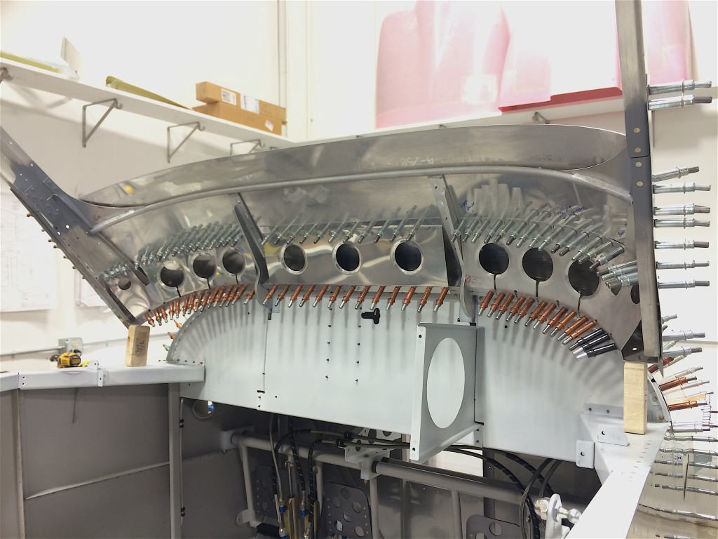
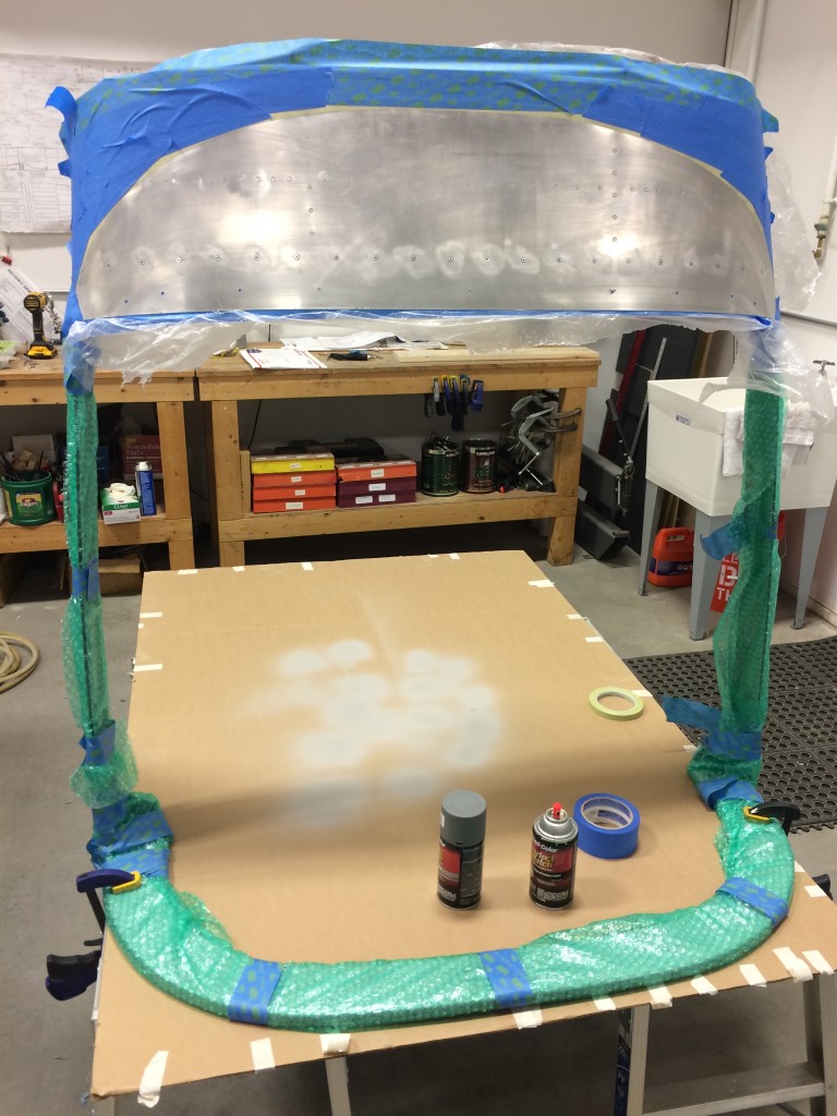
At long last, it’s time to prime the canopy skins and stiffeners, and rivet them to the frame.
Blecch…priming. I’m glad there isn’t much more to do.
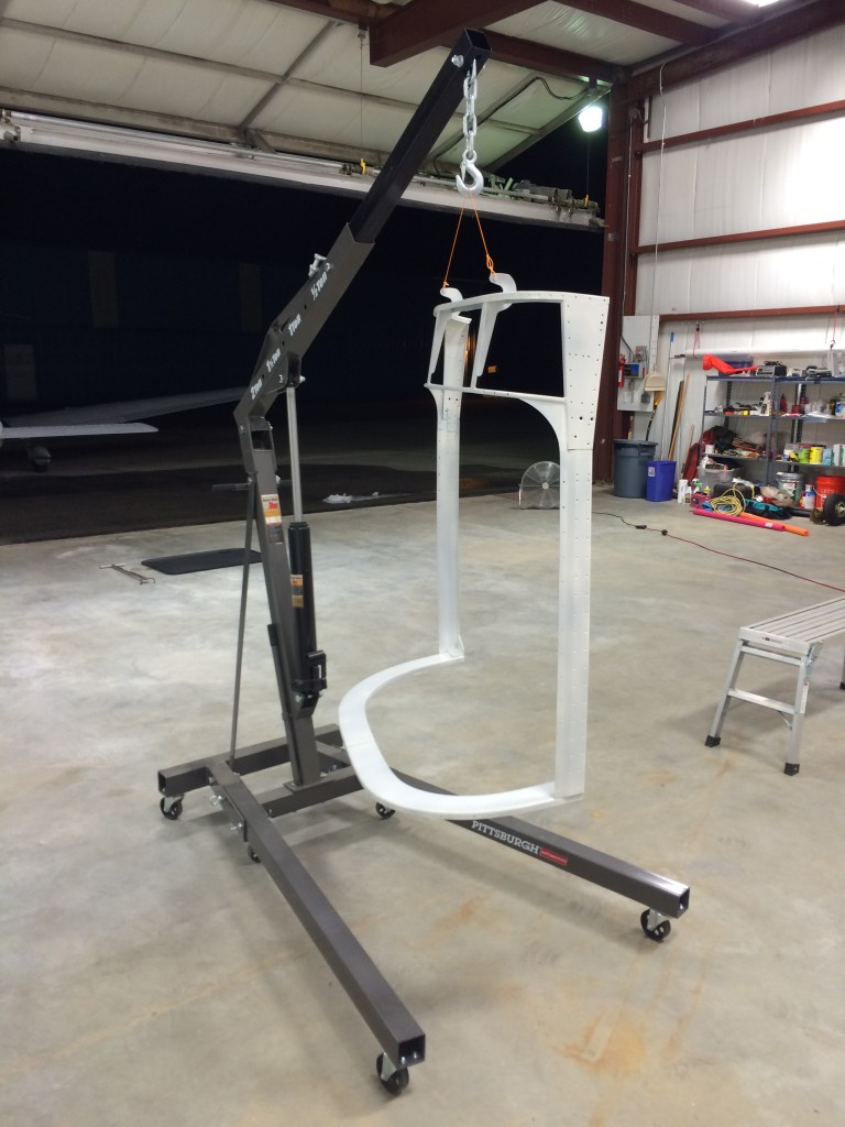
Priming the canopy frame was a pain, but hanging it from the engine stand made things easier.
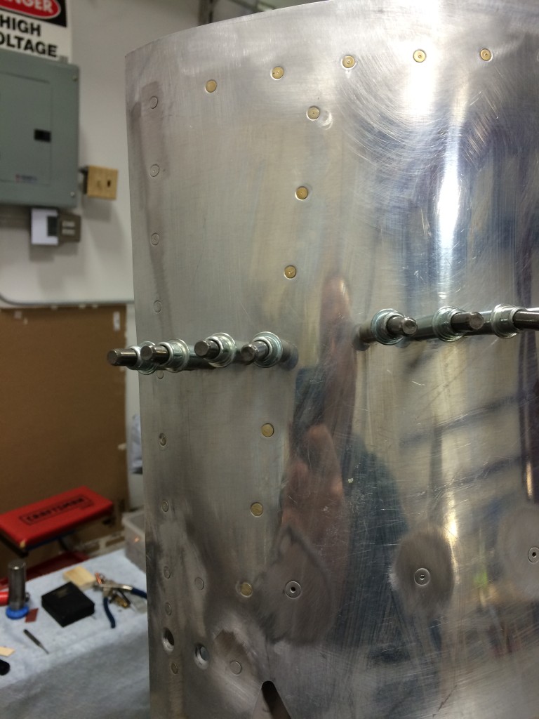
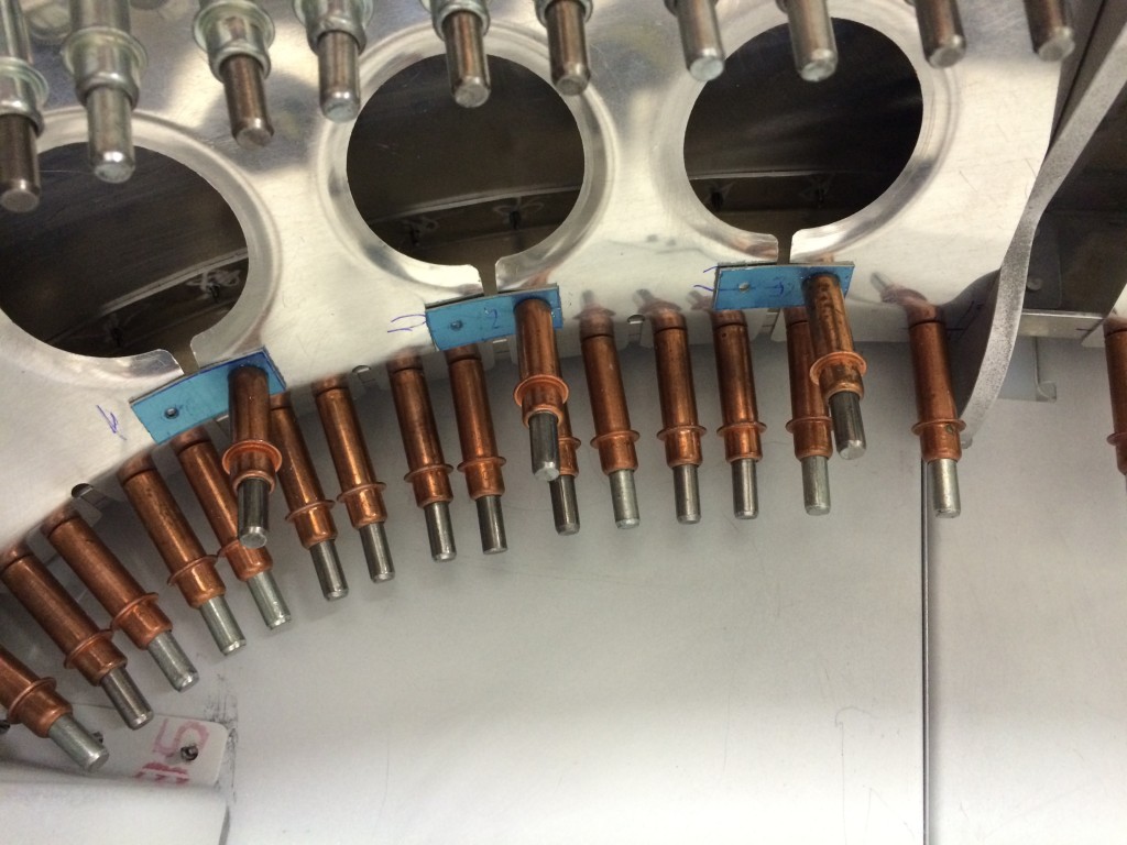
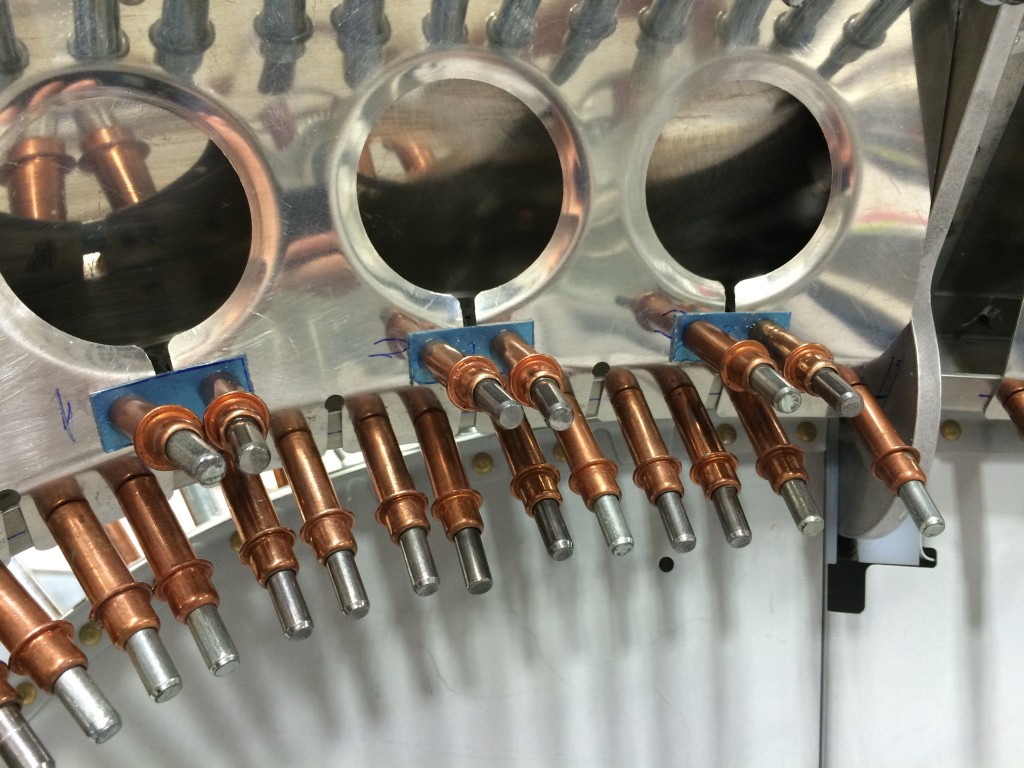
The canopy skin doesn’t fit particularly well on the frame, so I used an epoxy and flox mixture to fill gaps between the skin and frame. Once it cured, Bob DiMeo and I riveted the skins on. The epoxy/flox mixture worked pretty well – there aren’t the dimples in the canopy skin that I’ve seen on other projects.
More riveting fun, this time after several pop rivets have been pulled. The pop riveter takes some manual effort to use, and my forearms are aching.
Unfortunately I neglected to take any pictures while I painted the canopy frame interior with JetFlex WR. This took a long time…I did a lot of repainting to get a good finish, and it was a real pain.
After the JetFlex dried, I masked off the glareshield for surface prep, priming and painting.
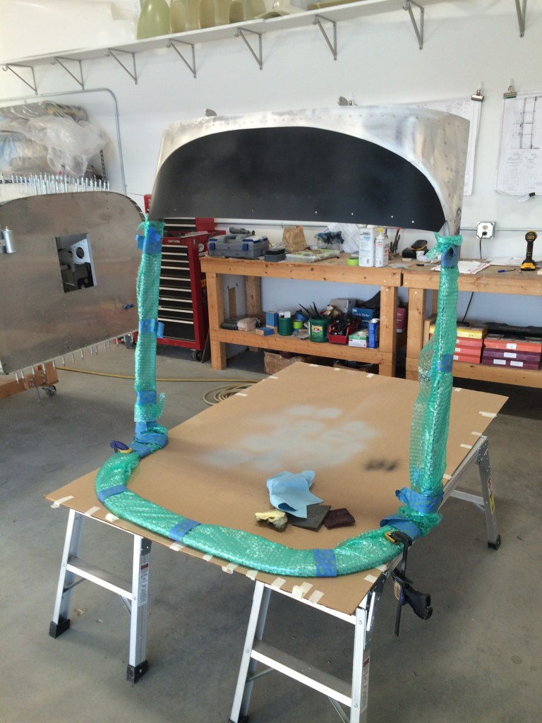
I used a good flat black automotive enamel to paint the glareshied, and it came out very nicely.
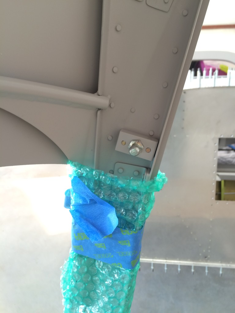
I installed the canopy strut pivots…kinda satisfying to do something so simple.

Here’s a bit of visual progress…the painted canopy frame with the canopy installed. Very cool!
Another picture? Sure, why not…
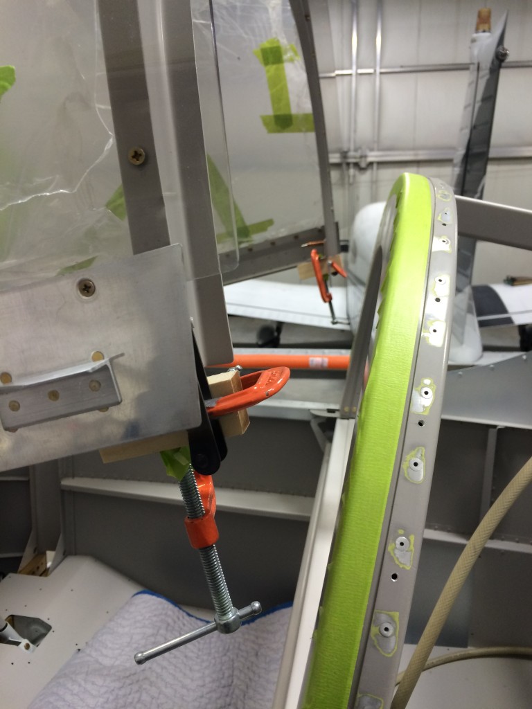
The last bit of work was installing the aft canopy latches.
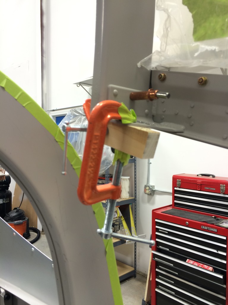
I don’t have much to add to the instructions, except that I had to do some improvising to keep the latch fingers clamped in place while I match-drilled them. A piece of spruce filled the bill.
I also clamped and drilled the upper canopy safety latch block to the canopy frame. Unfortunately, I forgot to take any pictures so you’ll have to use your imagination. I deviated from the plans a little and installed a spring beneath the washer and cotter pin that hold the handle in place. Once the block wears a bit and the handle turns more freely, the spring will pull the handle tight against the frame and keep it from inadvertently rotating to the close position, with the unfortunate effect of locking the canopy from the inside. It’s happened to other builders, and I’d like to avoid all the gyrations they had to endure to get the handle unlatched.
Most tip-up builders don’t go to the trouble of installing the canopy emergency release because (a) no one has ever bailed out of an RV-7, and (b) the release handle takes up valuable real estate on the instrument panel.
I’ve been debating the merits of installing the release for a few years, and finally came to the conclusion that I’d rather have it and not need it rather than the other way around. I also want to keep the instrument panel relatively simple, and keeping space for the release handle forced me to do that.
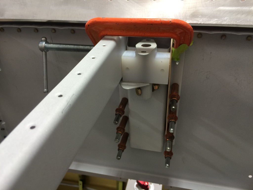
The first step was to drill the release pivot block to the hat section on the subpanel.
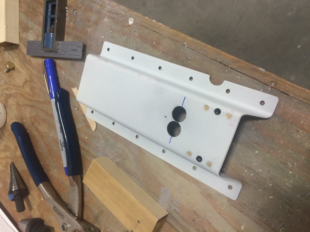
With the holes drilled, I installed nutplates to accommodate the attach bolts.
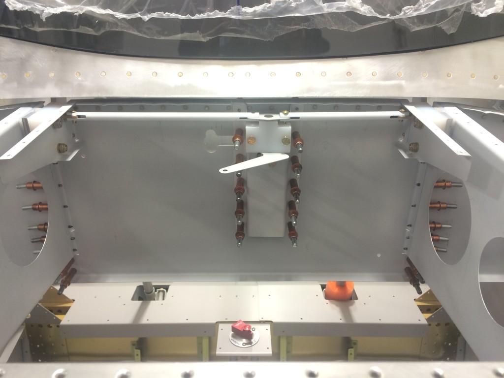
In this picture the pivot block and actuator arm are in place and attached to the canopy hinge pins with steel rods. Actually, the left rod isn’t connected to the actuator because the rod was slightly short even though it was fabricated according to the plans. So…I got to fabricate another one that was 1/16″ shorter.
There’s not much to add about fabricating the steel parts, except that the slots in each steel rod that accommodate the actuator and pins are most easily cut with a Dremel tool with a cutoff wheel. Some work with files will still be required, but the Dremel will get 95 percent of the cutting done.
The release mechanism is on the shelf now, and will be reinstalled right before I’m ready to rivet the front fuselage skin in place.