Rear Window

It’s December 29 and I’m finally getting a chance to complete this post on finishing the rear window. So for all you Mighty RV fans out there (I think we’re now up to three), here’s a narrative on trimming, fitting, marking and drilling the final part of the canopy.

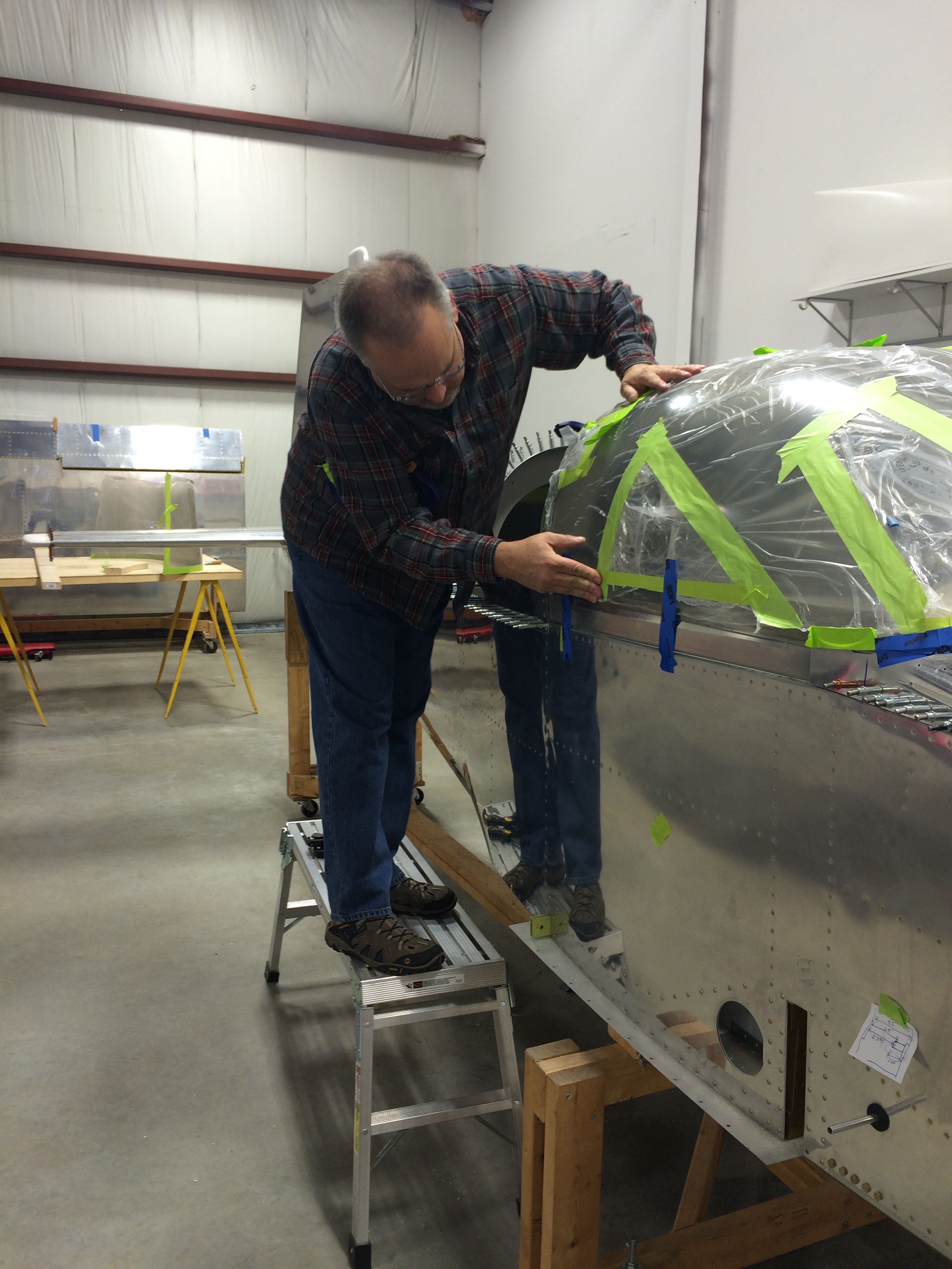
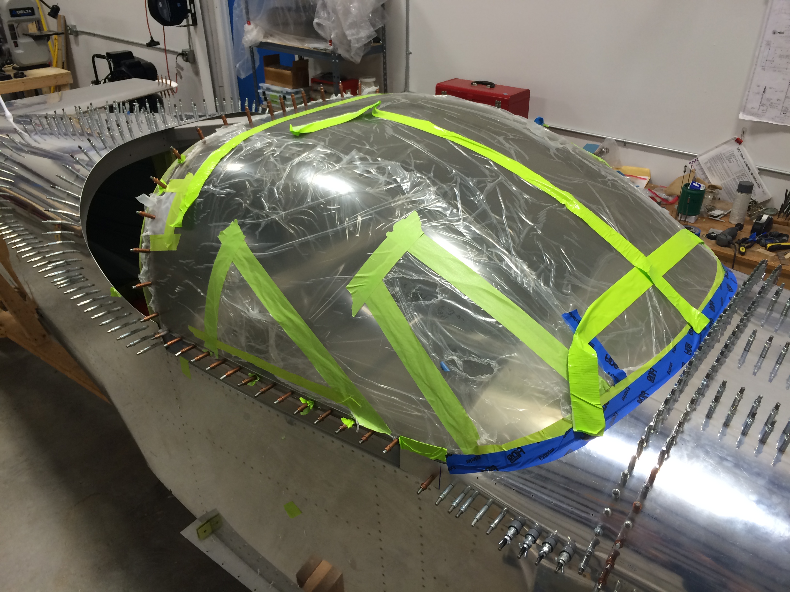
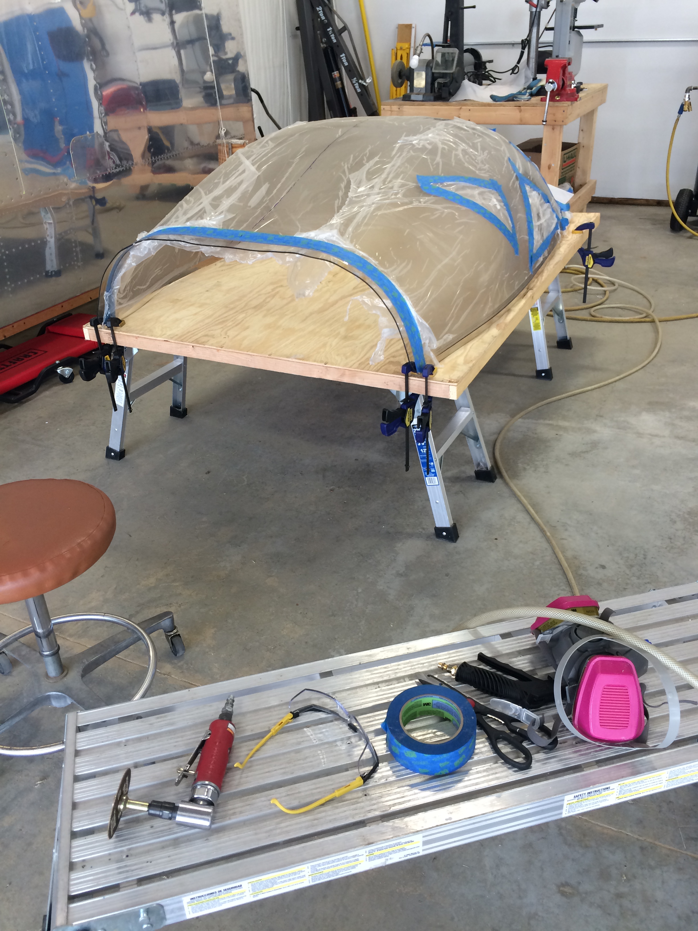
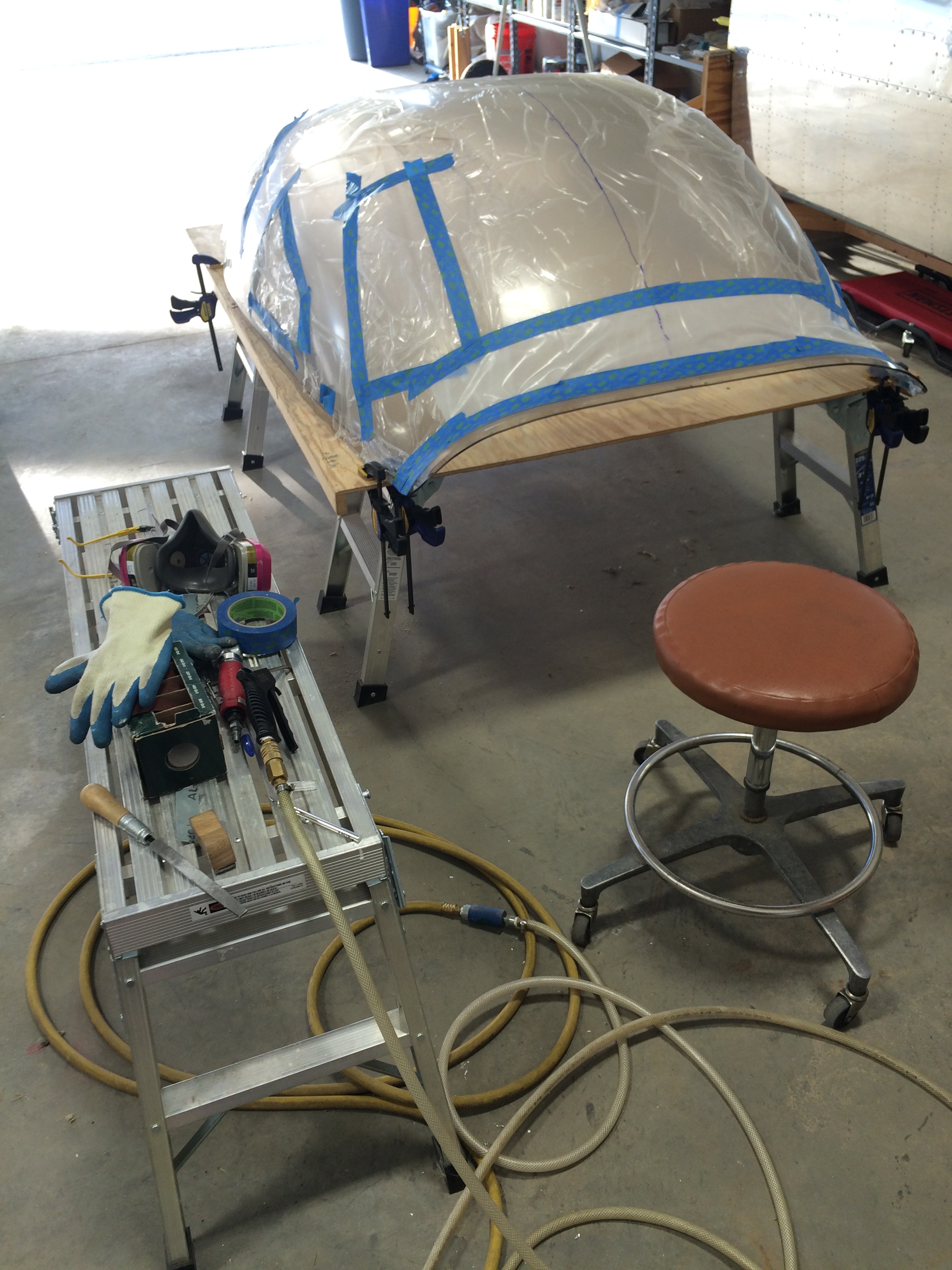
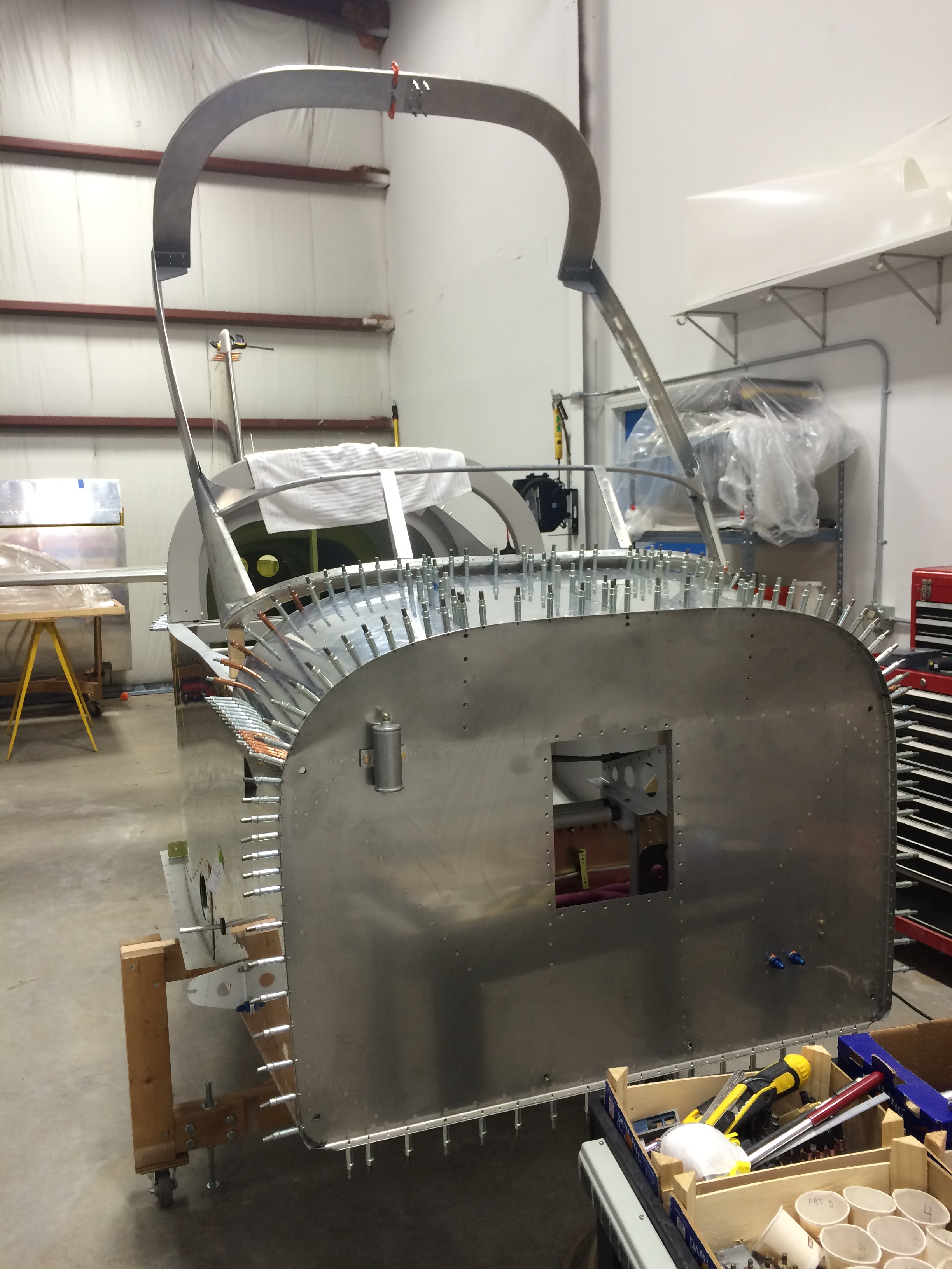
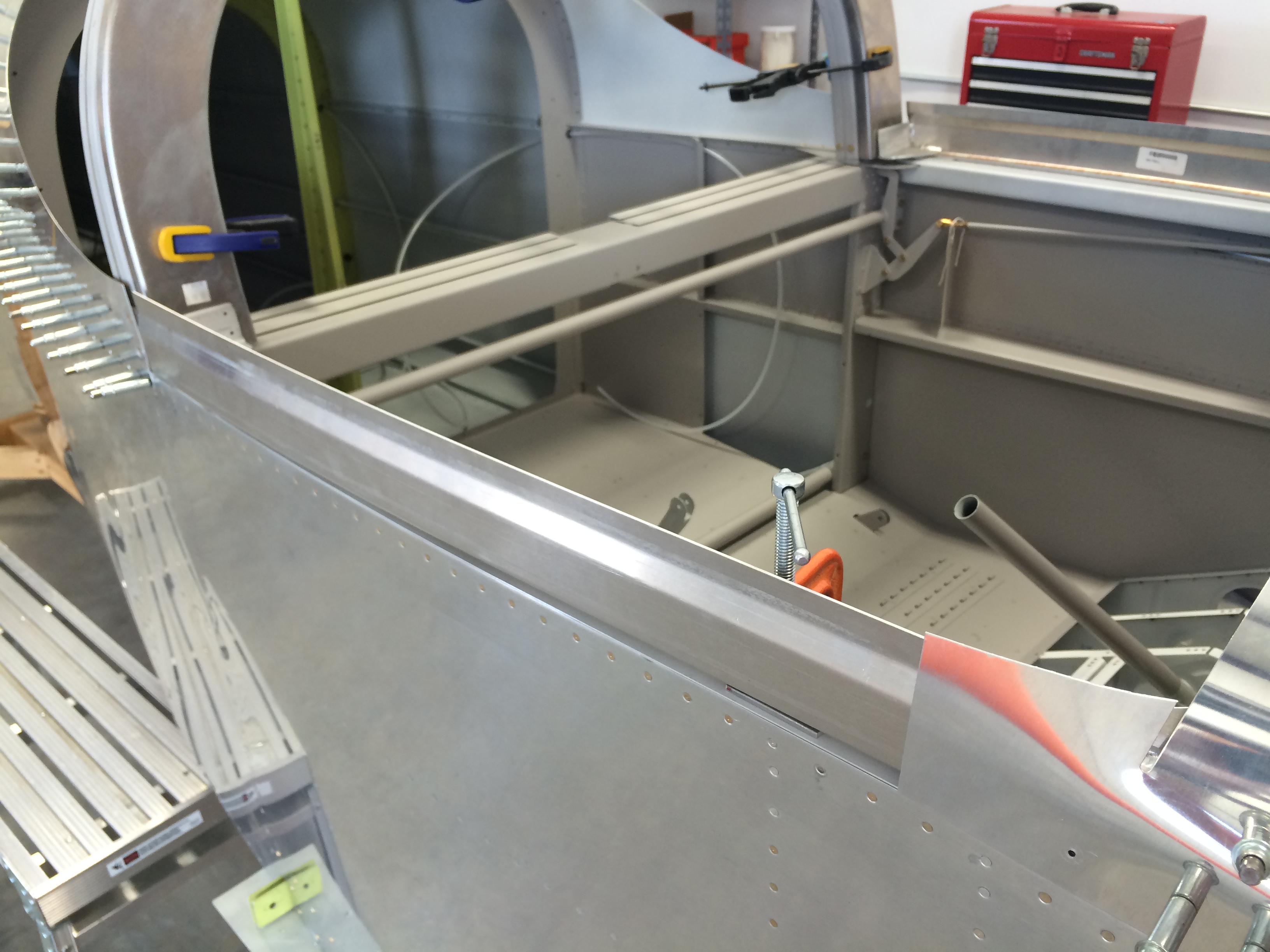
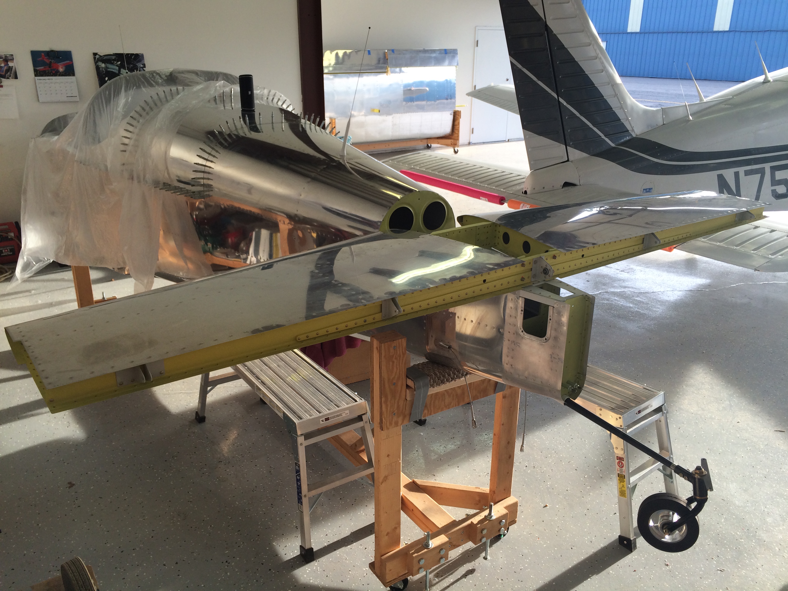
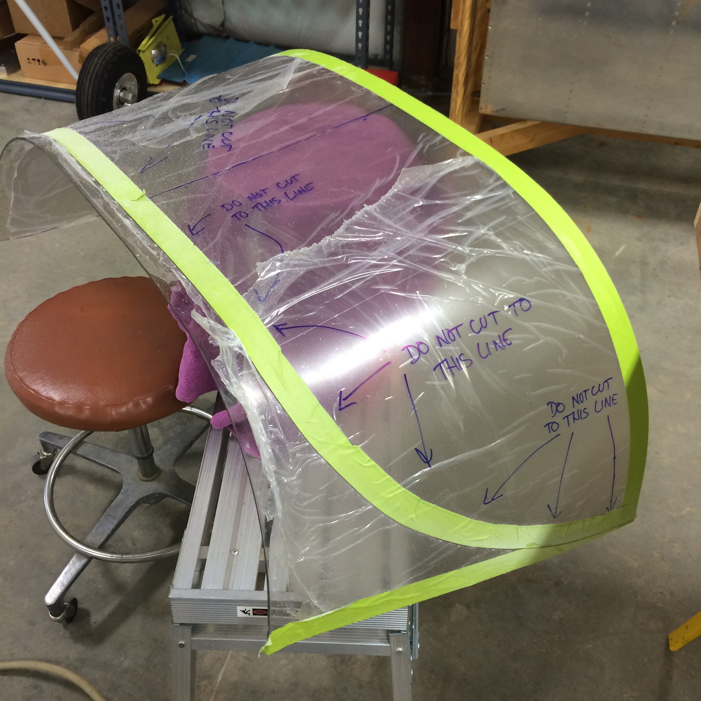
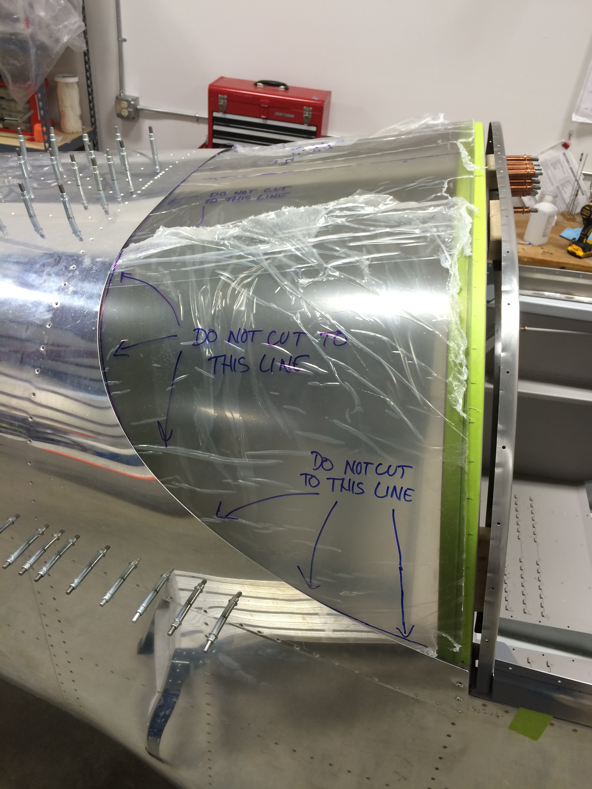
Vans’ instructions call for rough-marking the rear canopy trim line before cutting the canopy into forward and rear sections. For some reason I didn’t do that, so with the forward canopy separated and placed in approximately the right position, I laid the rear canopy over the fuse and marked a “do not cut” line around the fuselage skin edge.  Yeah, I went over the top with reminders about where not to cut…

Rear window marked for cutting

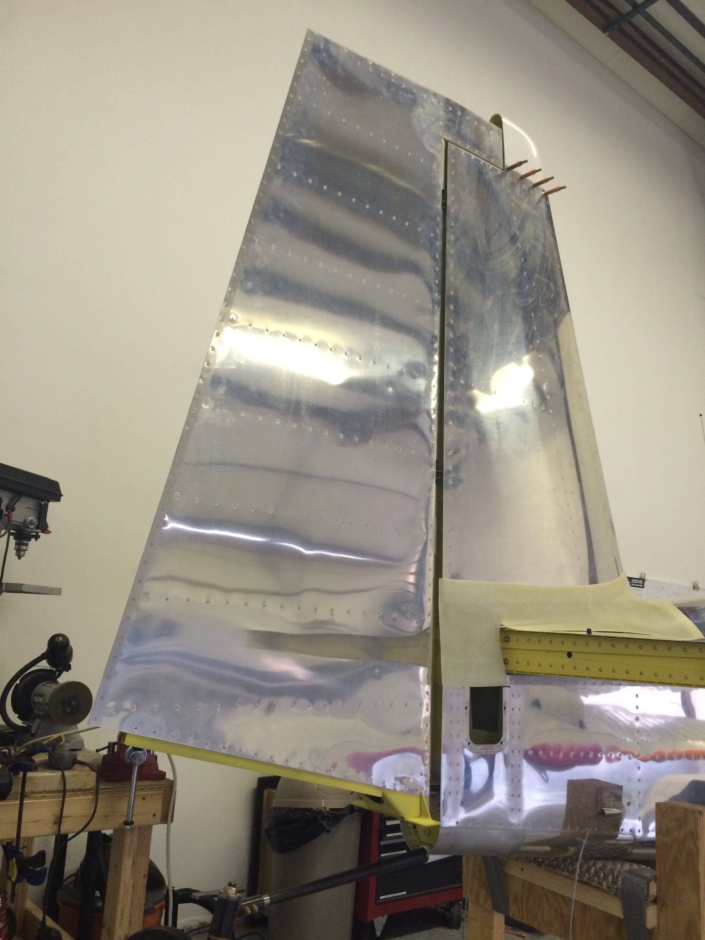
I then did a rough estimate of a “cut here” line based on the no-cut line. I don’t recall the distance, but it was generous – I took off just enough so that the canopy would fit under the skin.

Rear window cut line taped

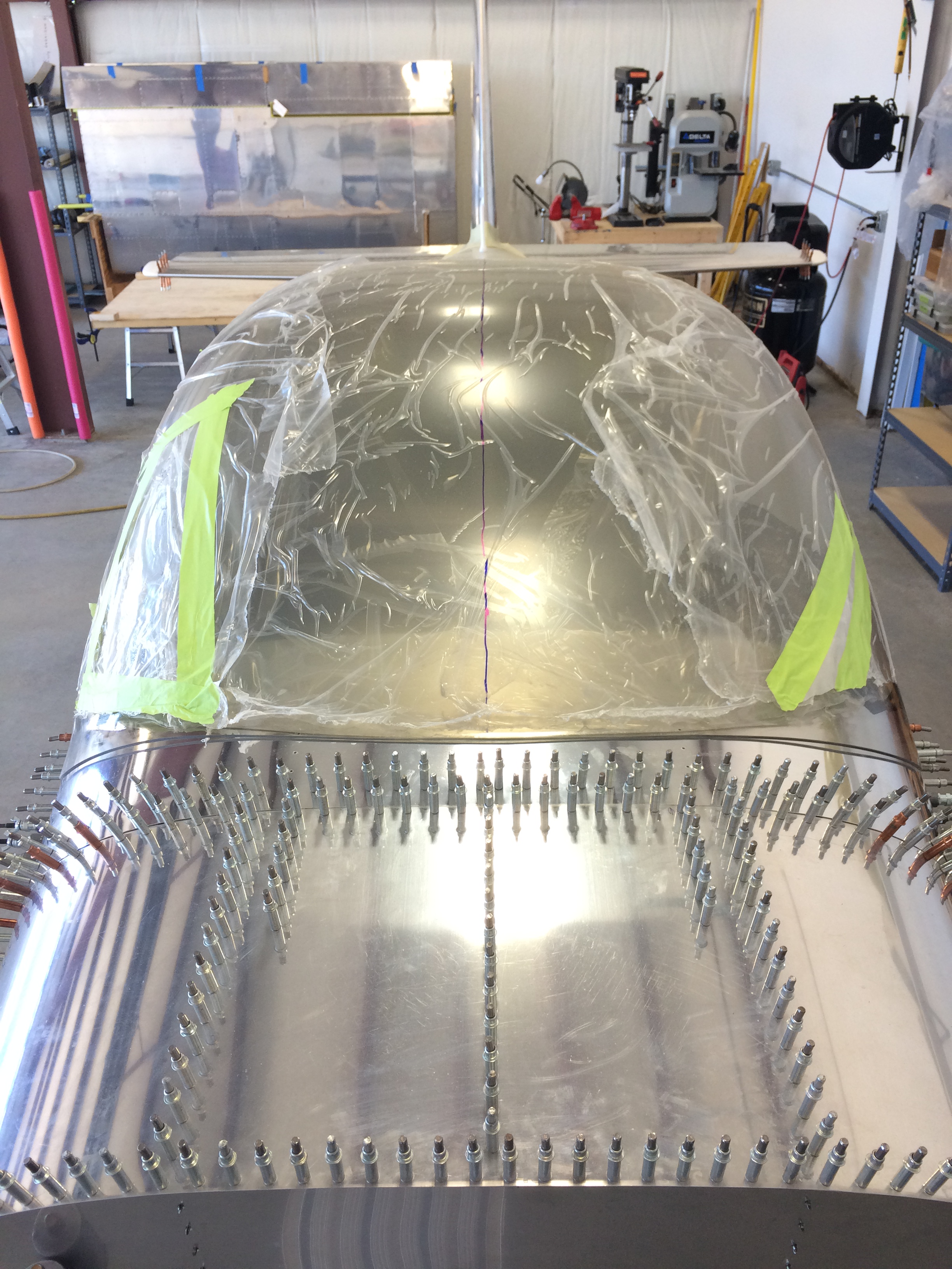
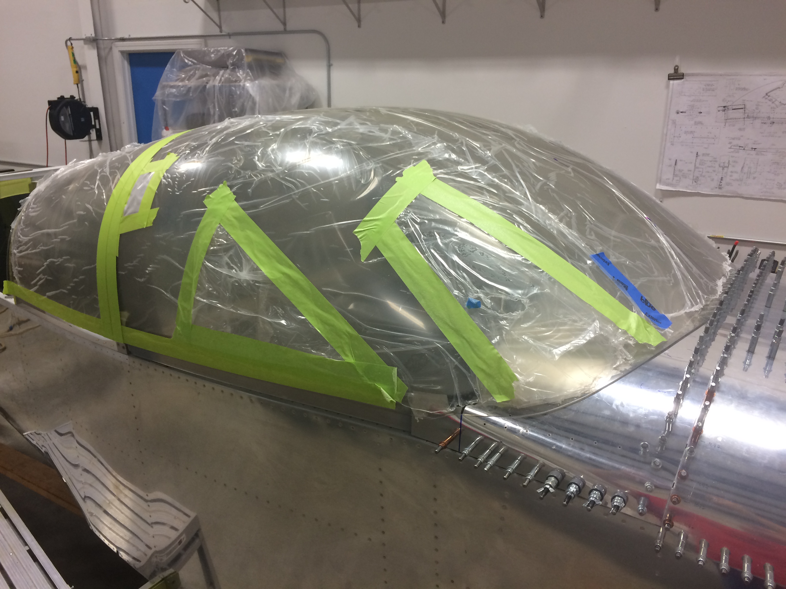
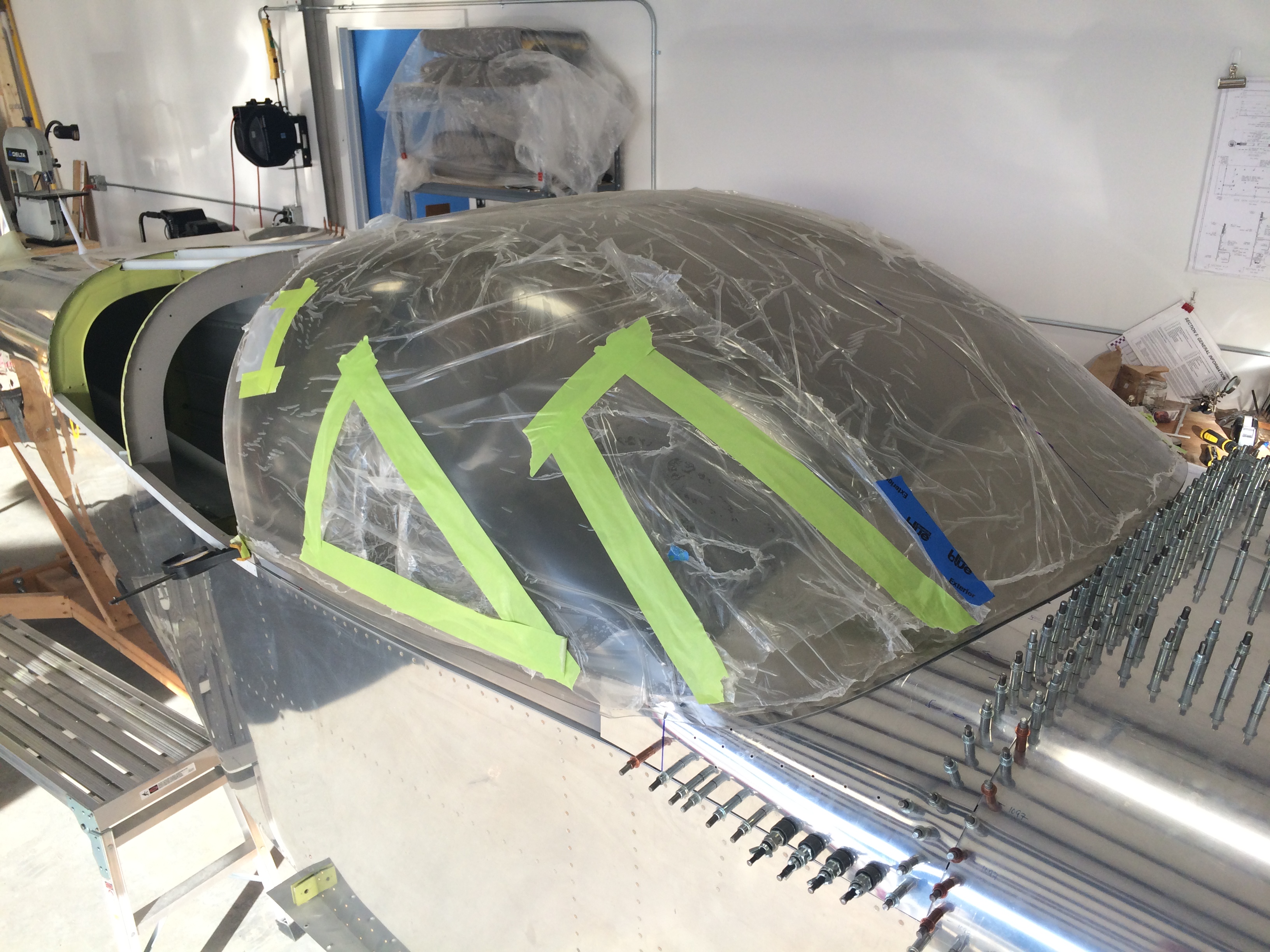
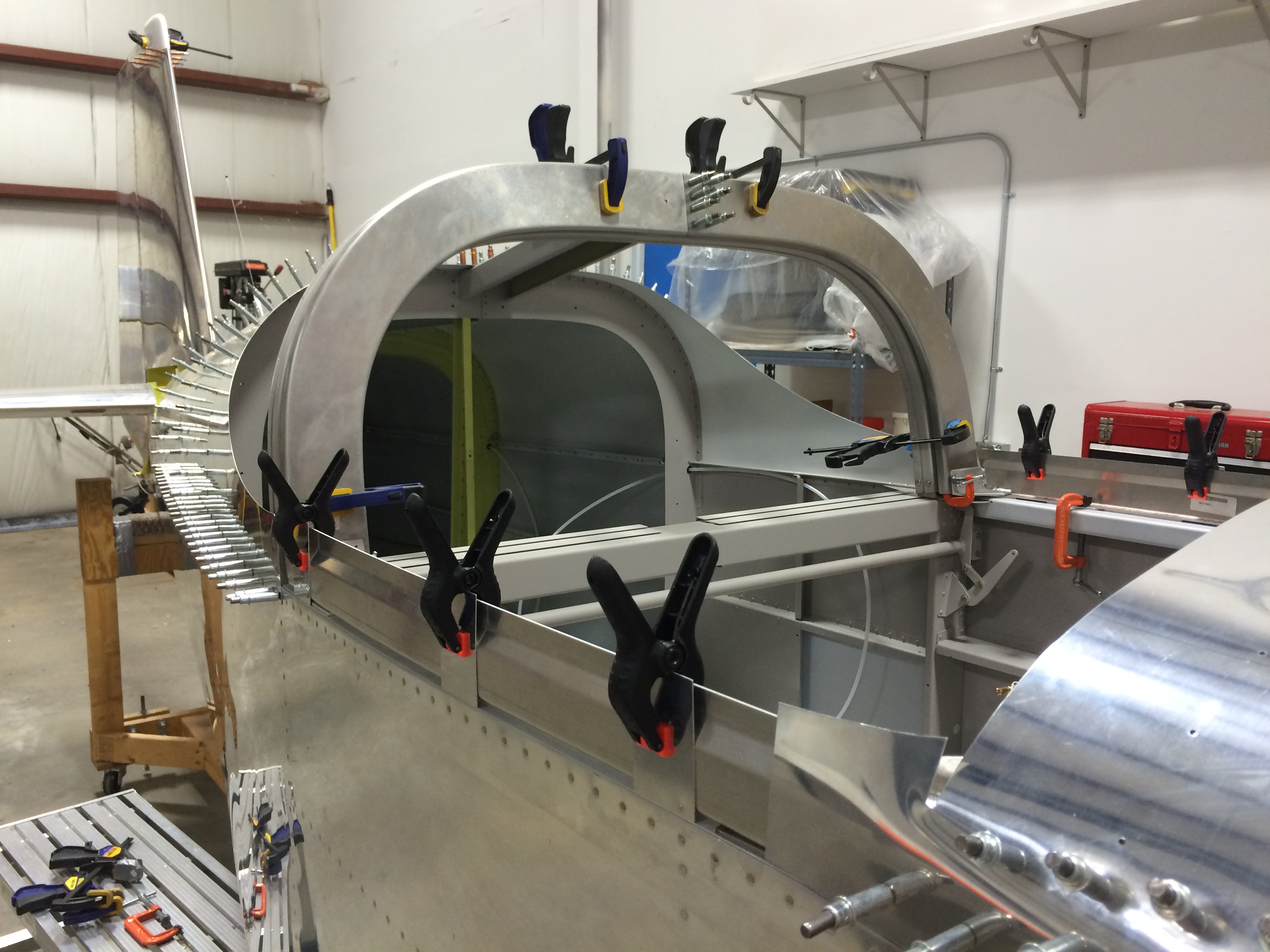
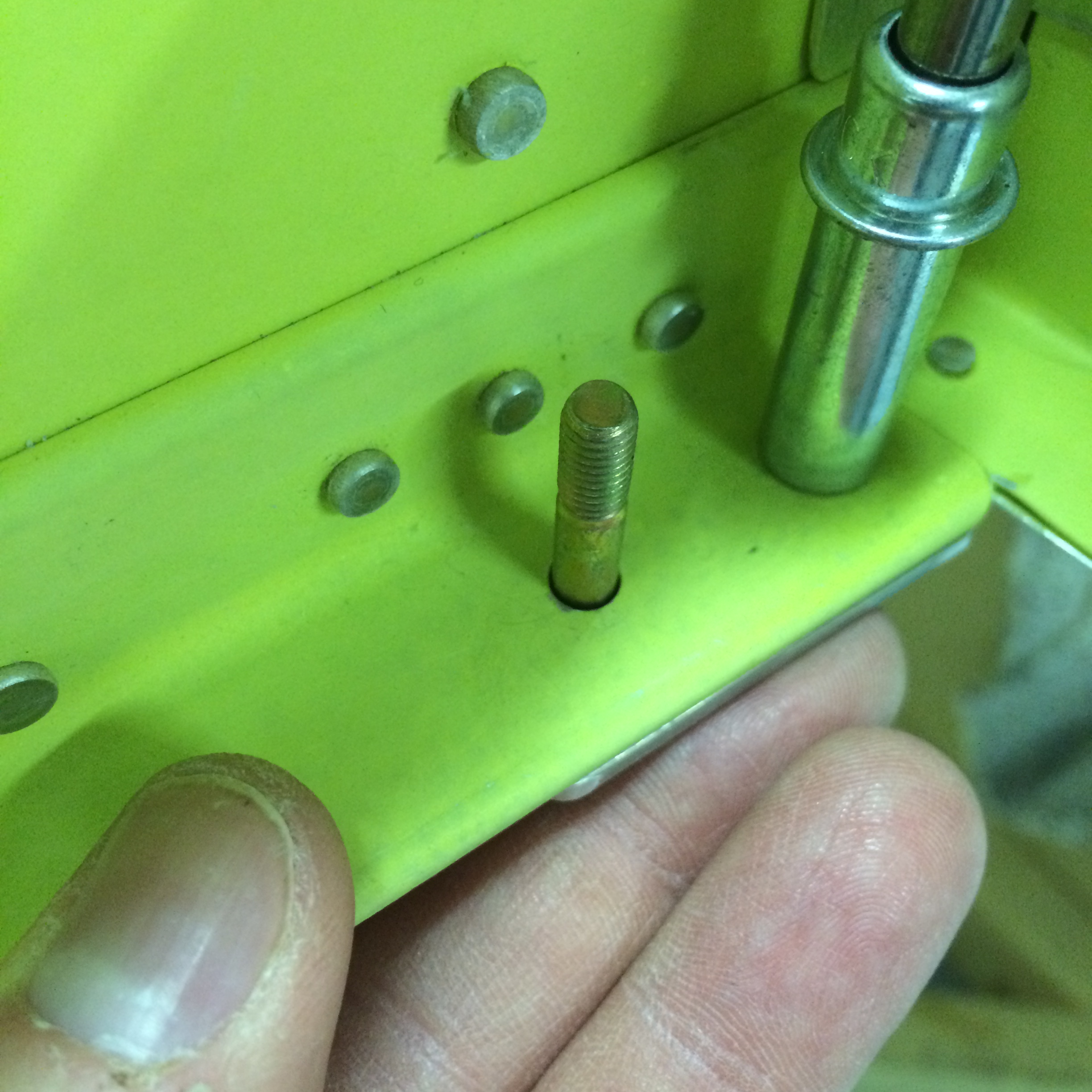
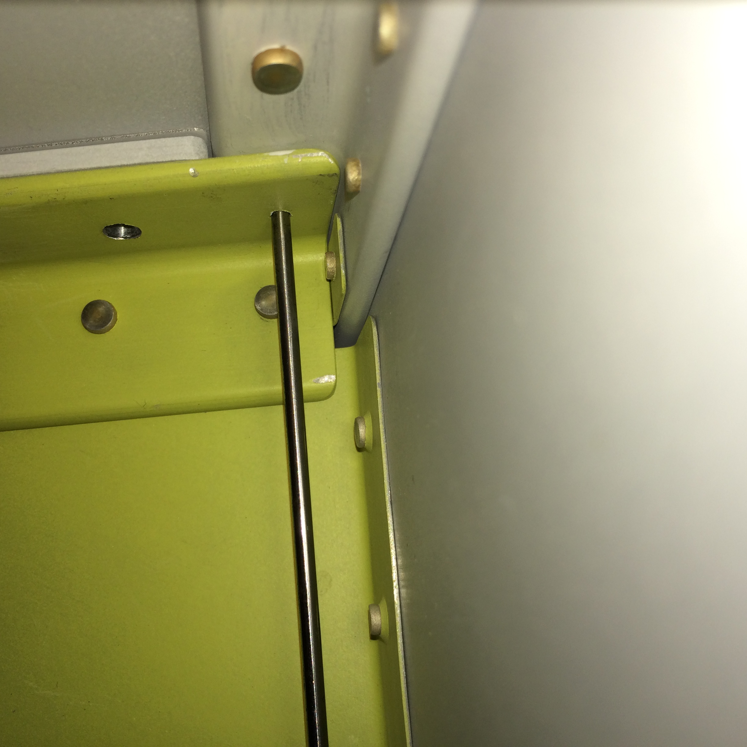
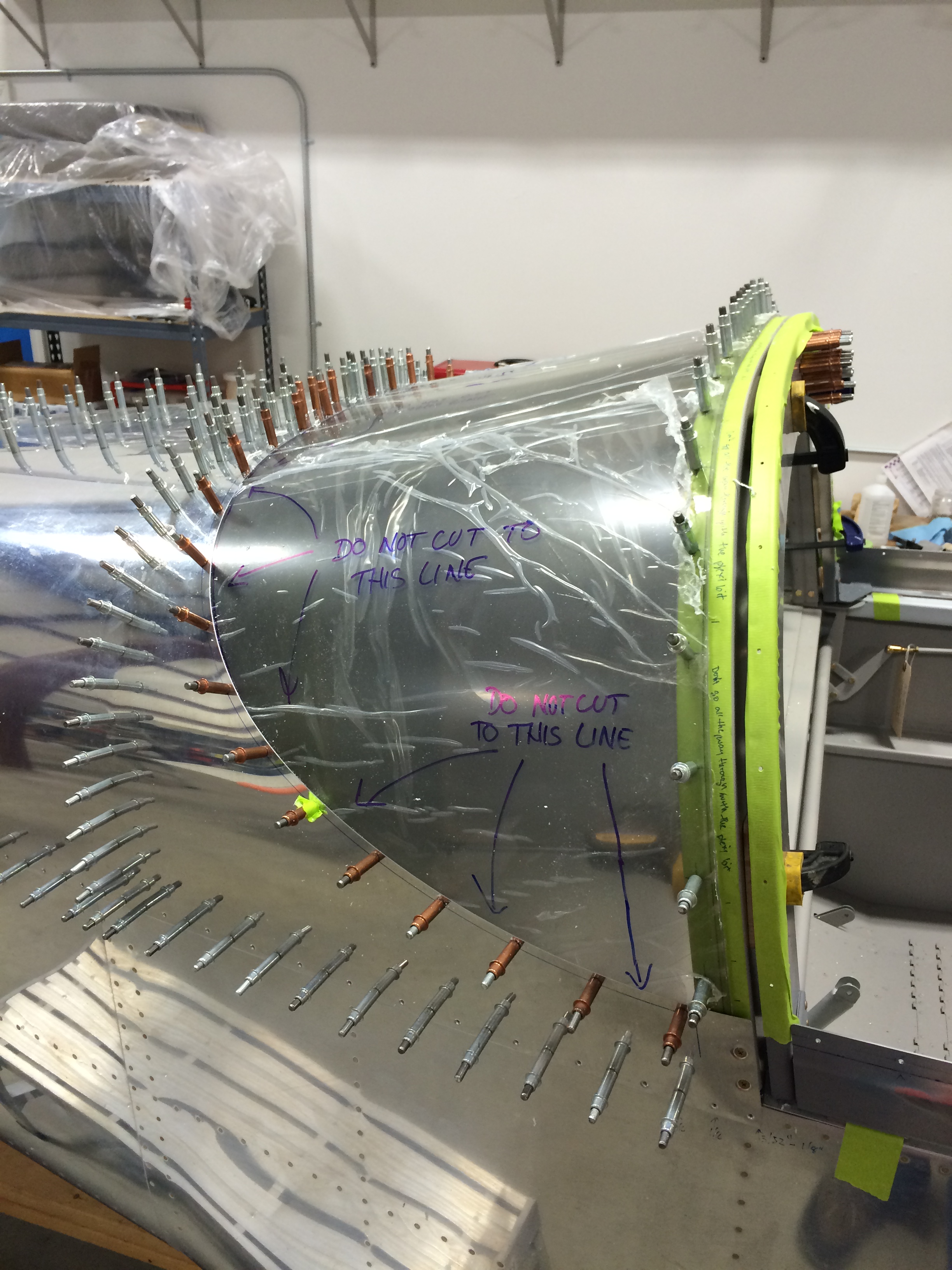
Here’s the first cut line marked with masking tape. I like that Scotch yellow-green masking tape…it just looks more “aerospace-y.”

Rear window trimmed and temp fitted

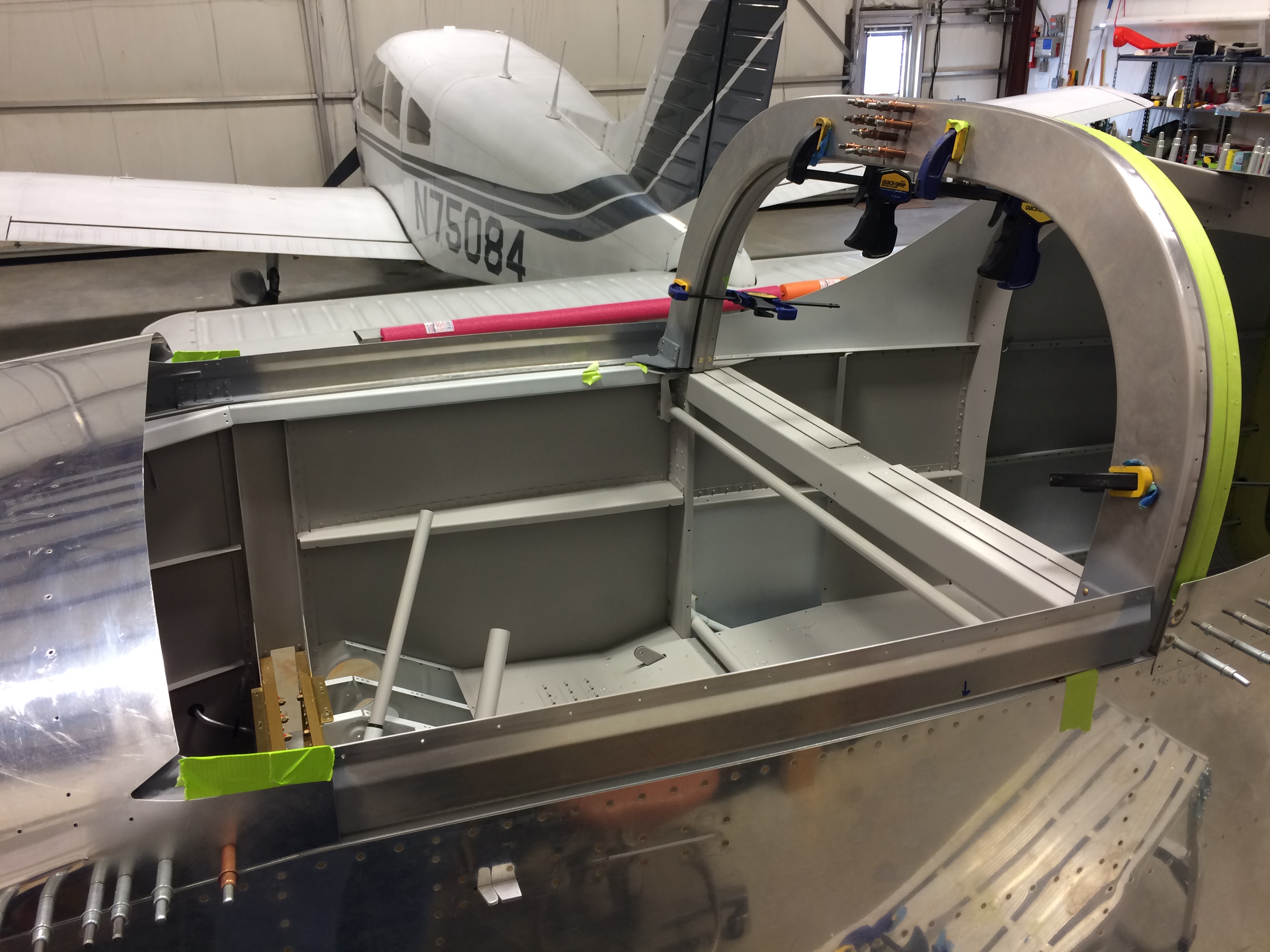
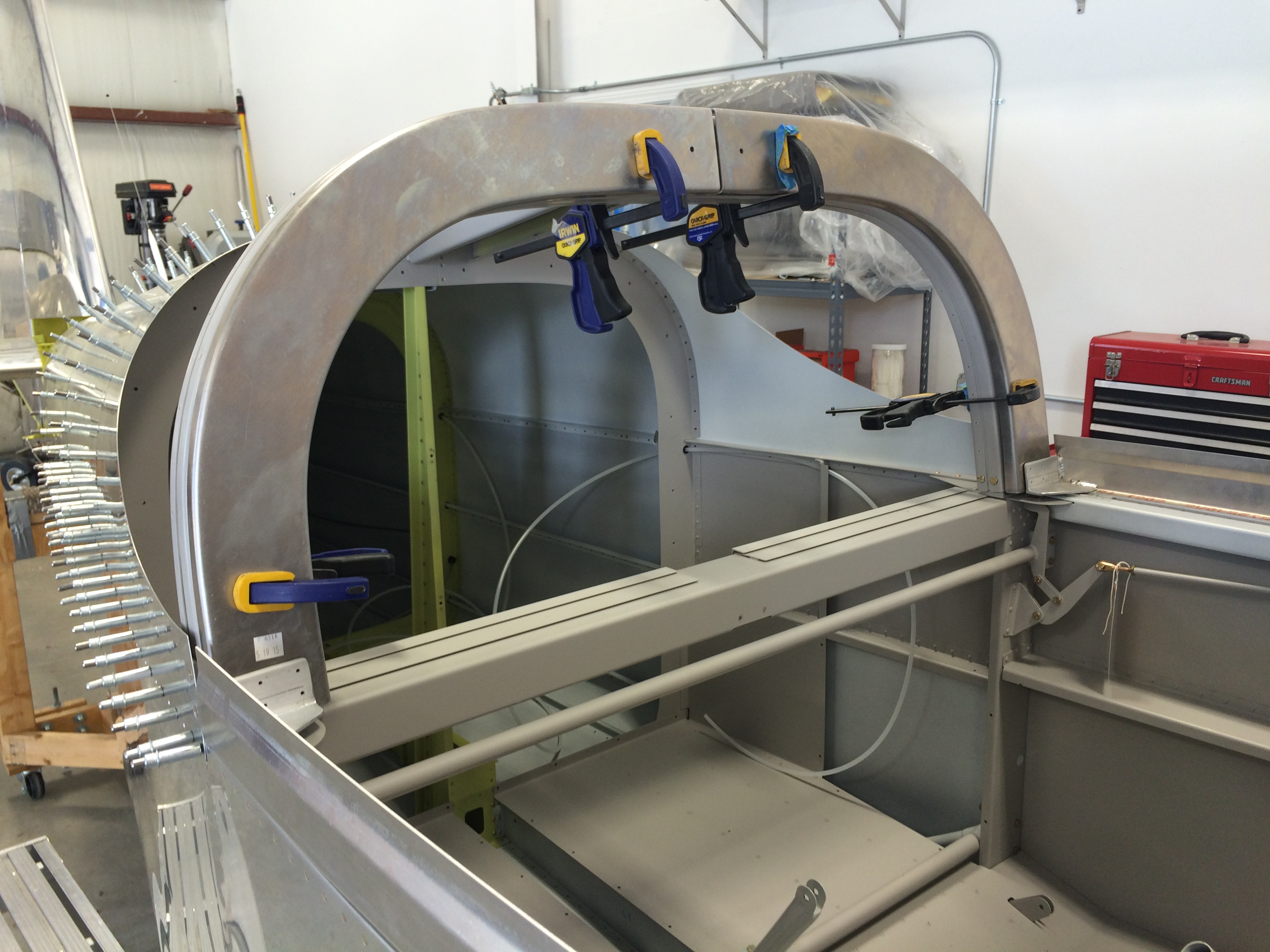
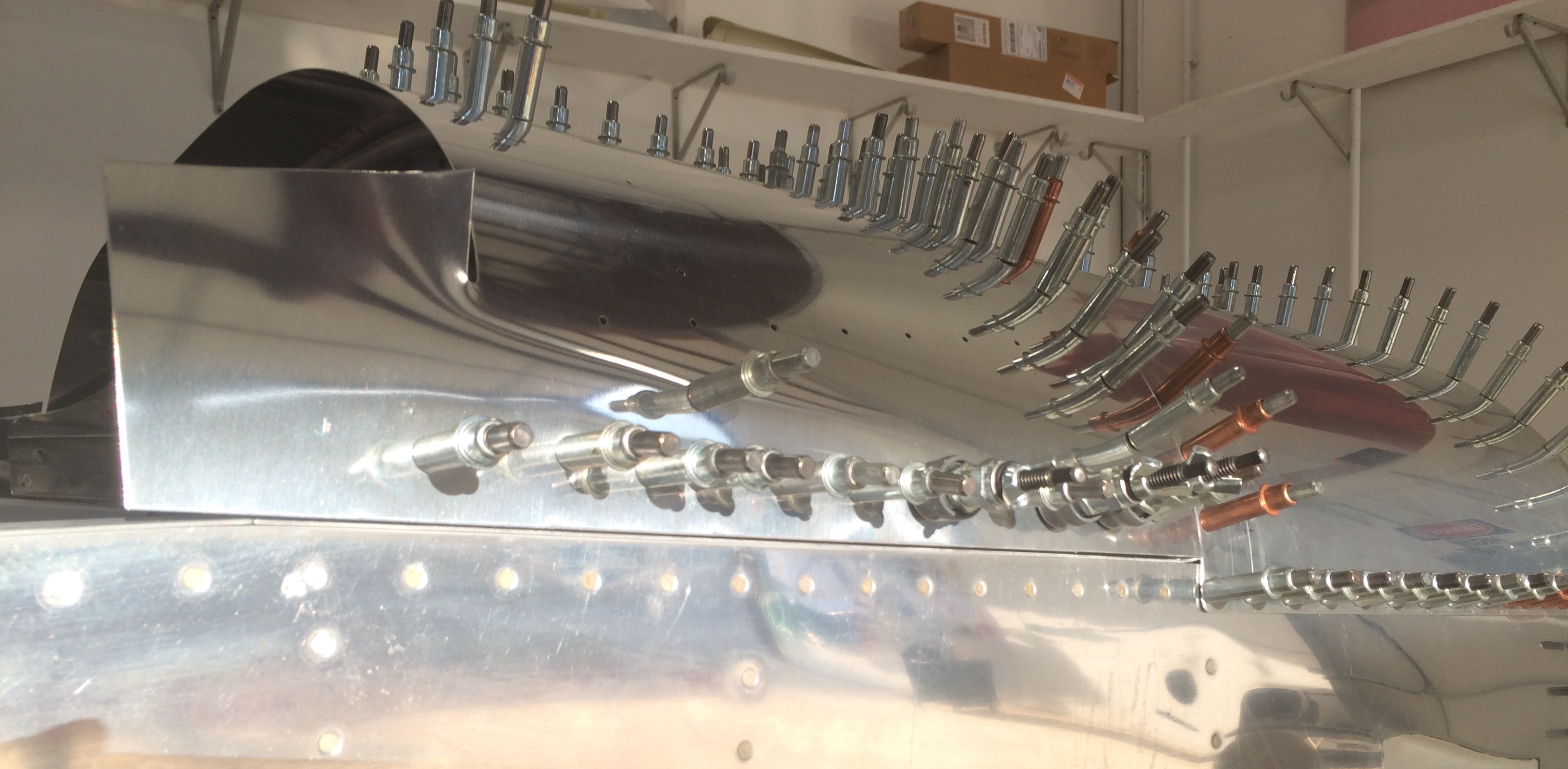
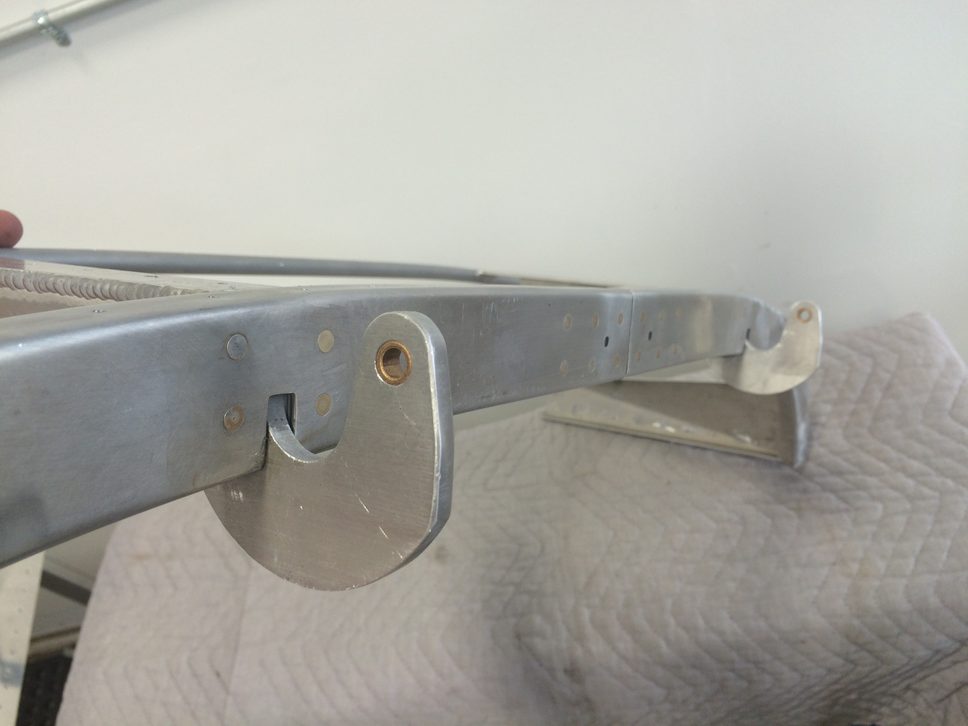
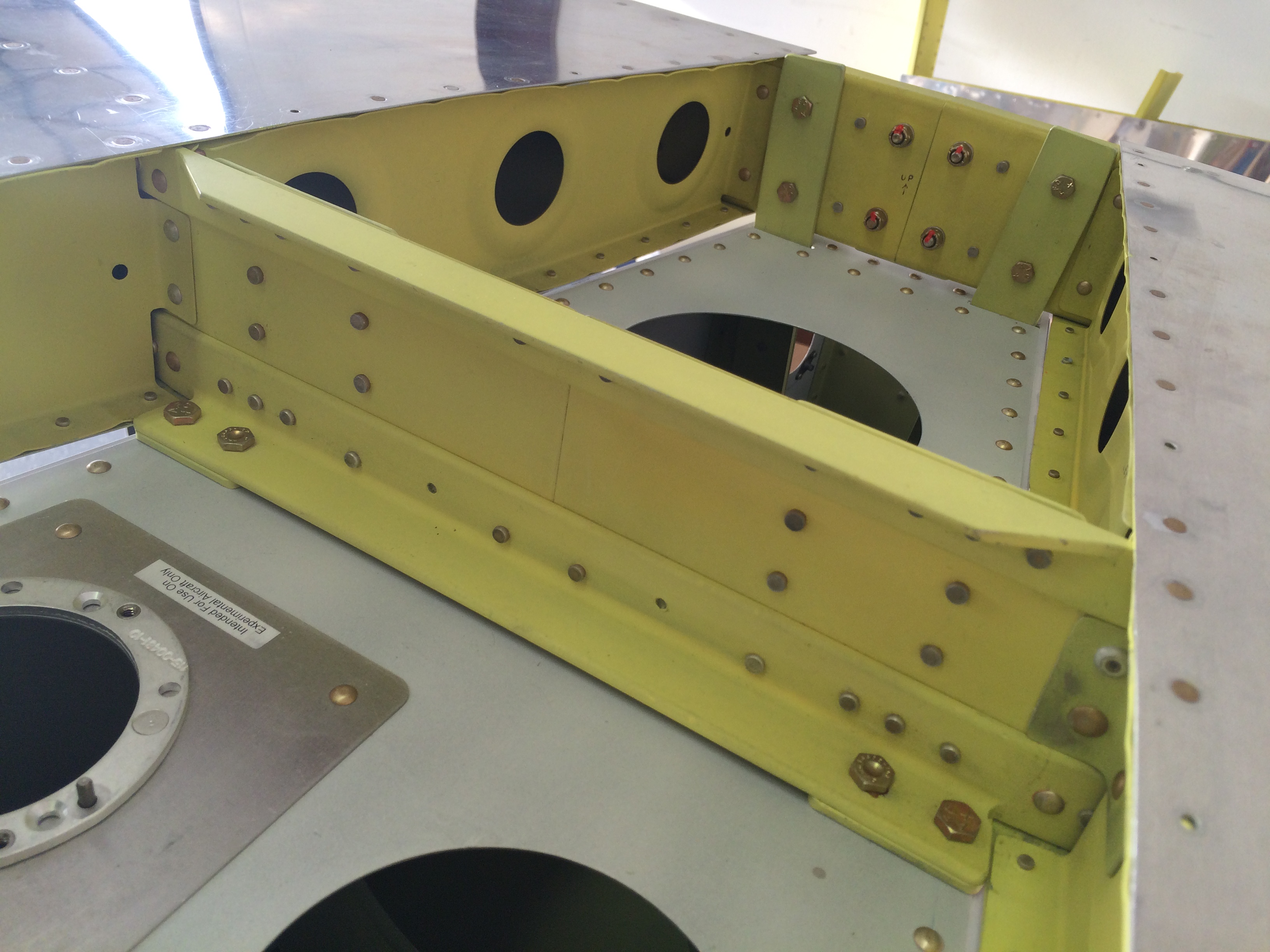
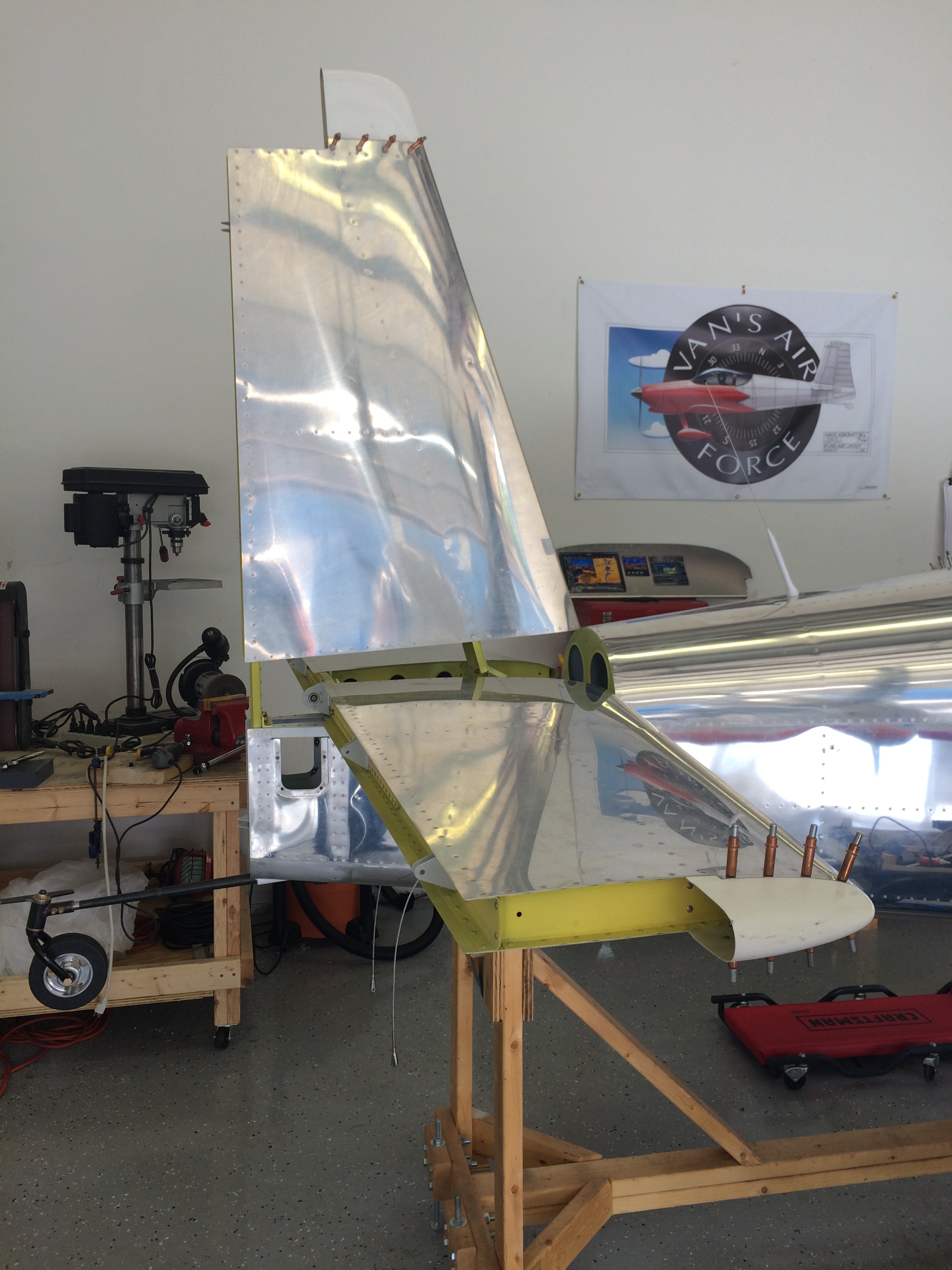
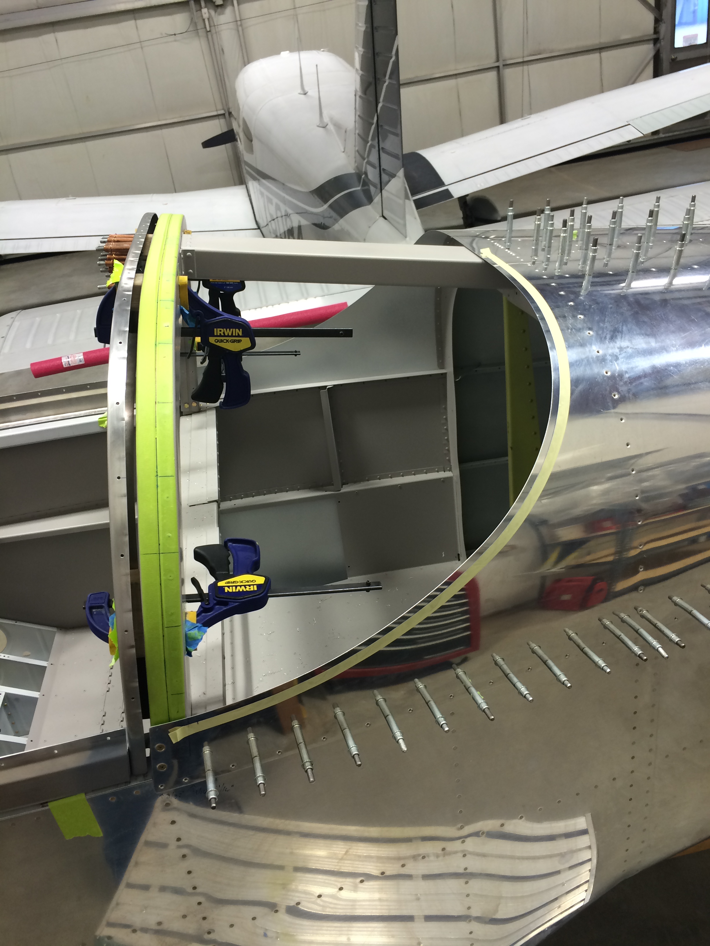
I got the first trim cut just about right; the rear canopy seats nicely around the skin edge, and there’s enough overlap of the roll-bar to make it easy to final-trim the forward cut line that abuts the front canopy.

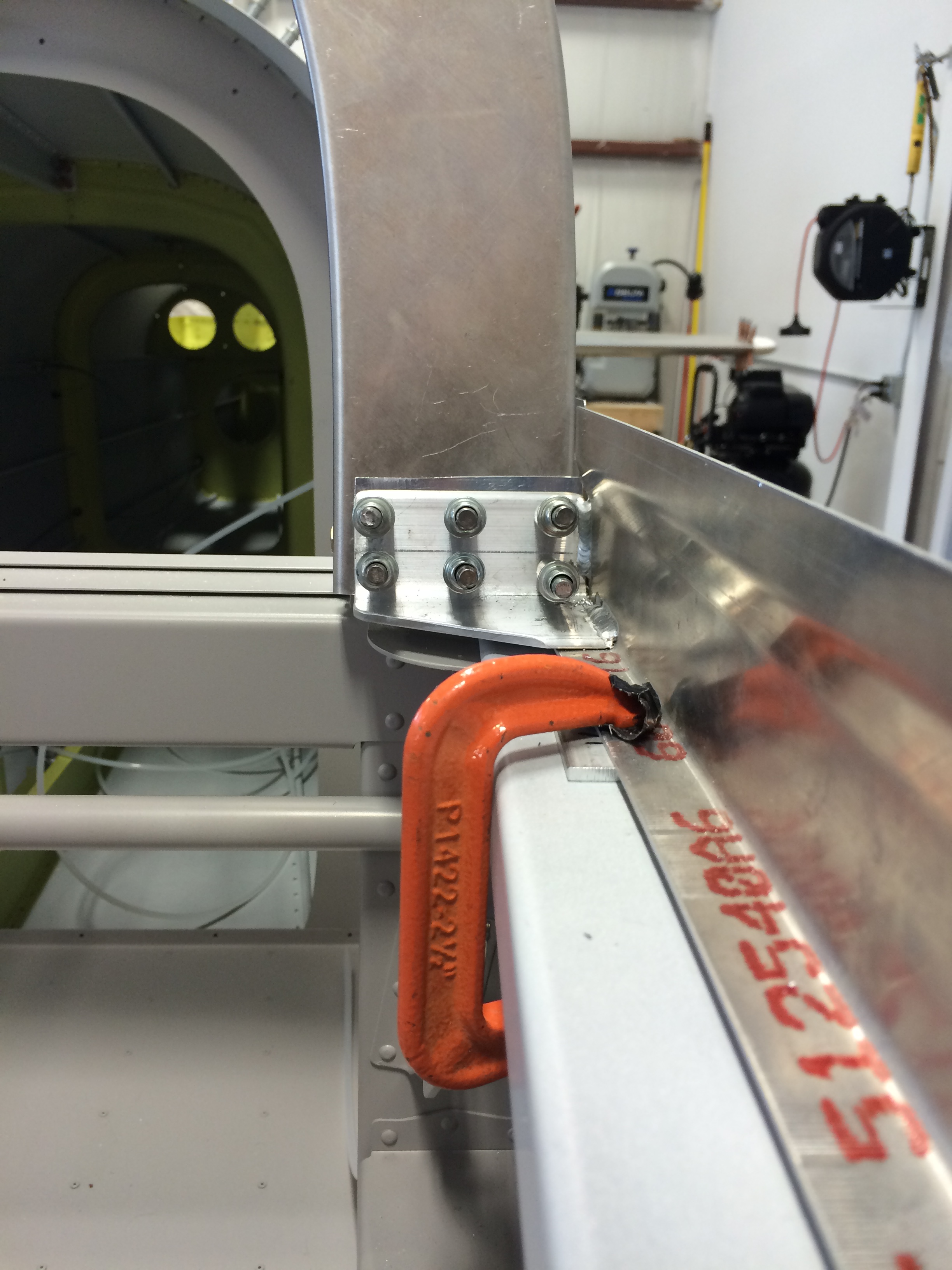
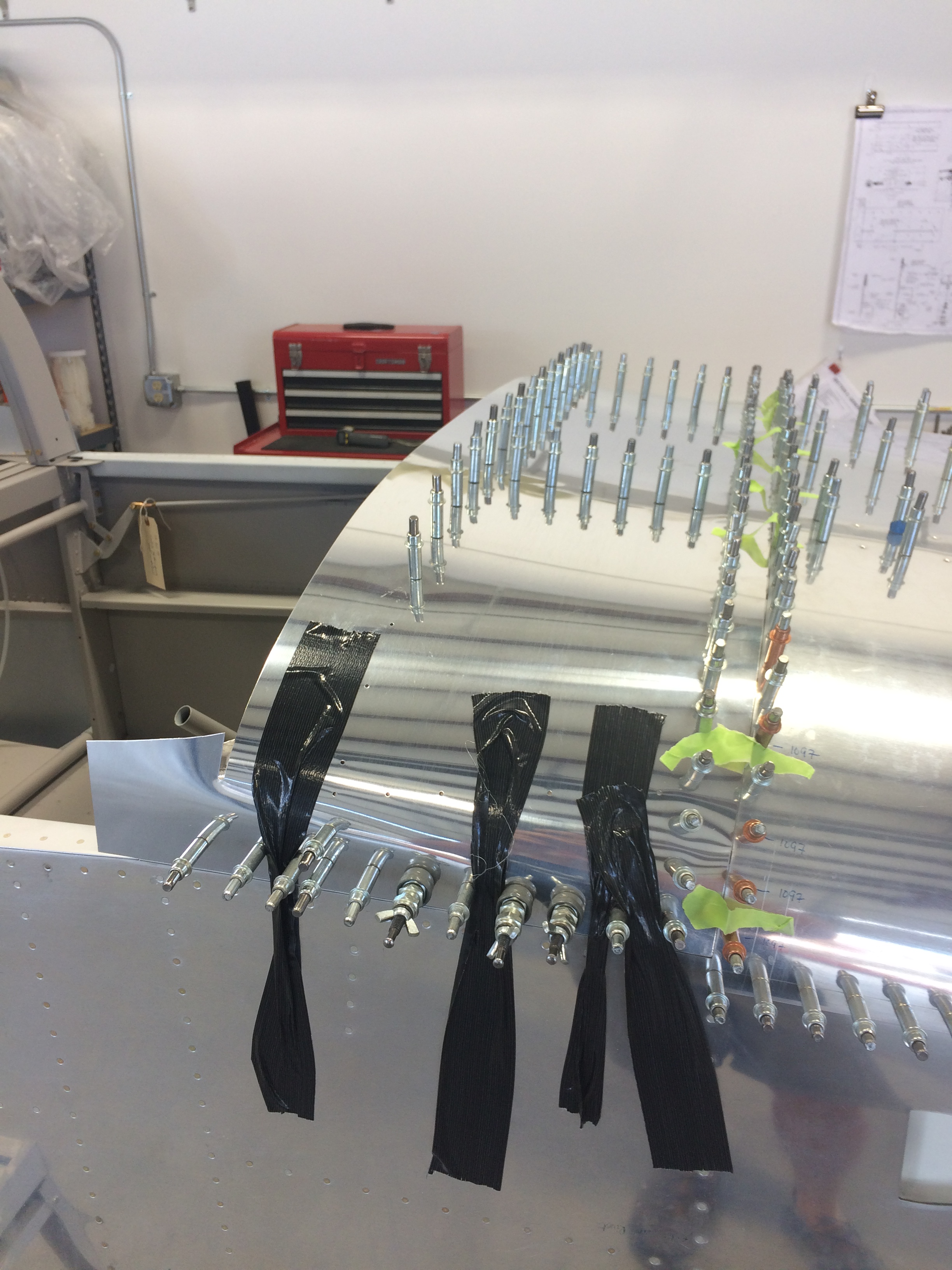
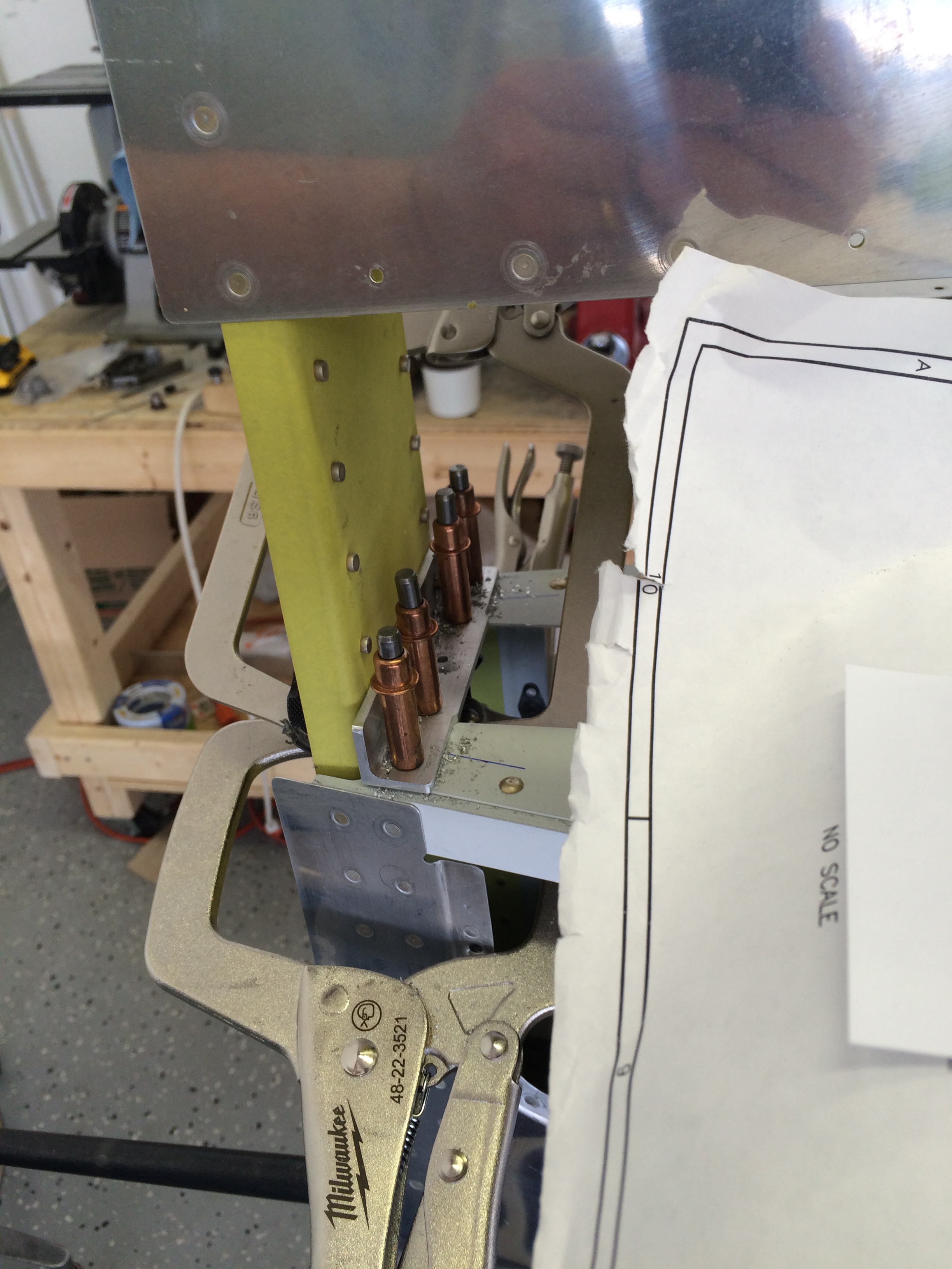
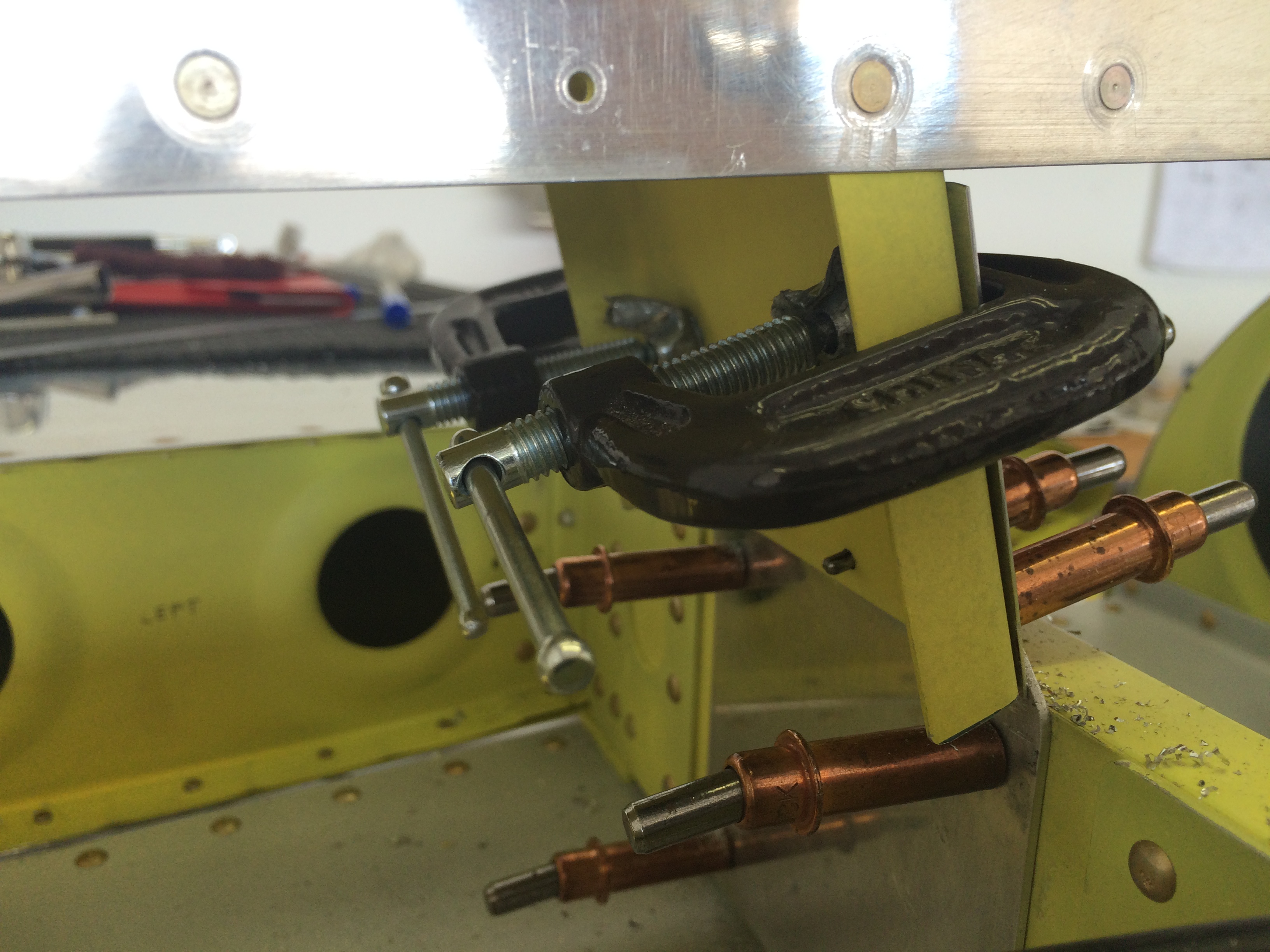
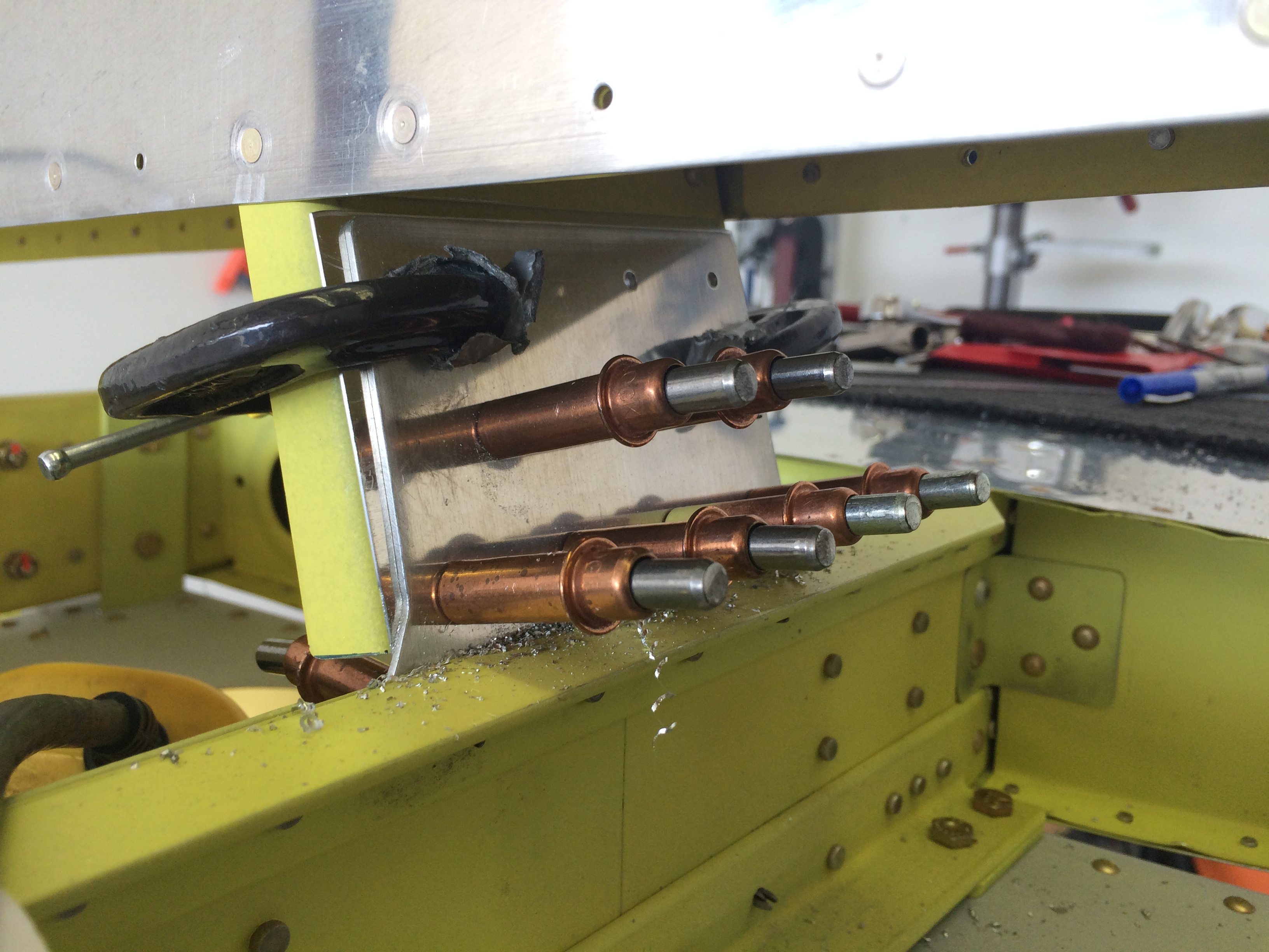
The only thing you can’t see in the above picture are the bits I had to cut out of the forward lower corners of the rear canopy so they’d fit around the roll-bar attach fittings.

Rear cabin skin screw line layout

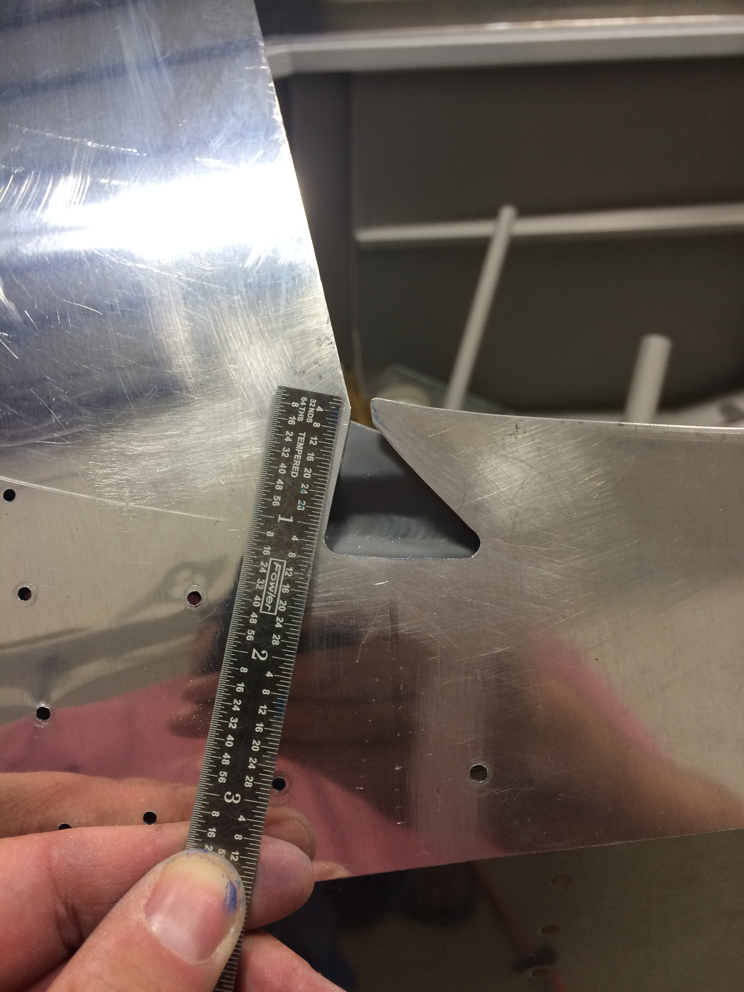
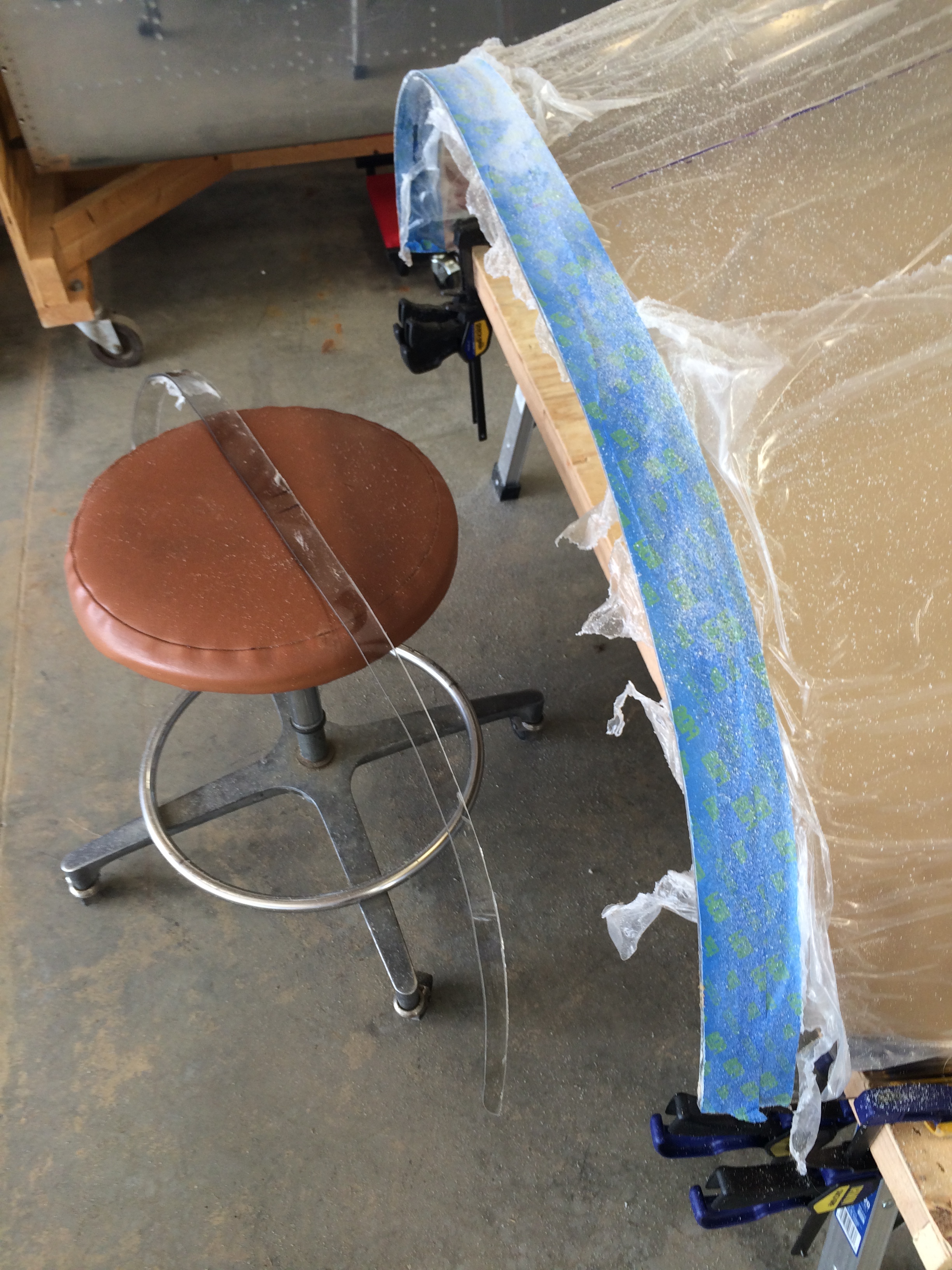
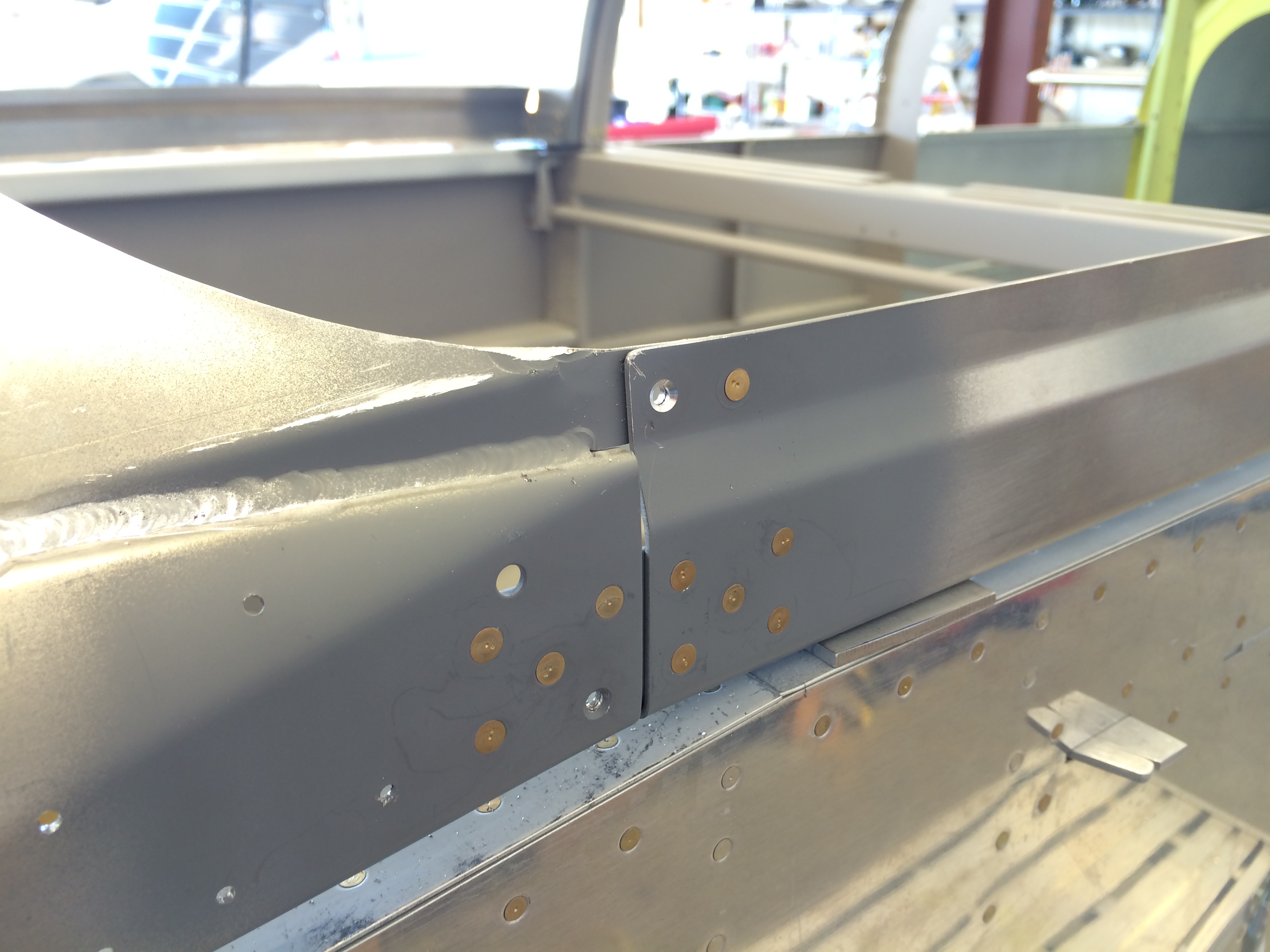
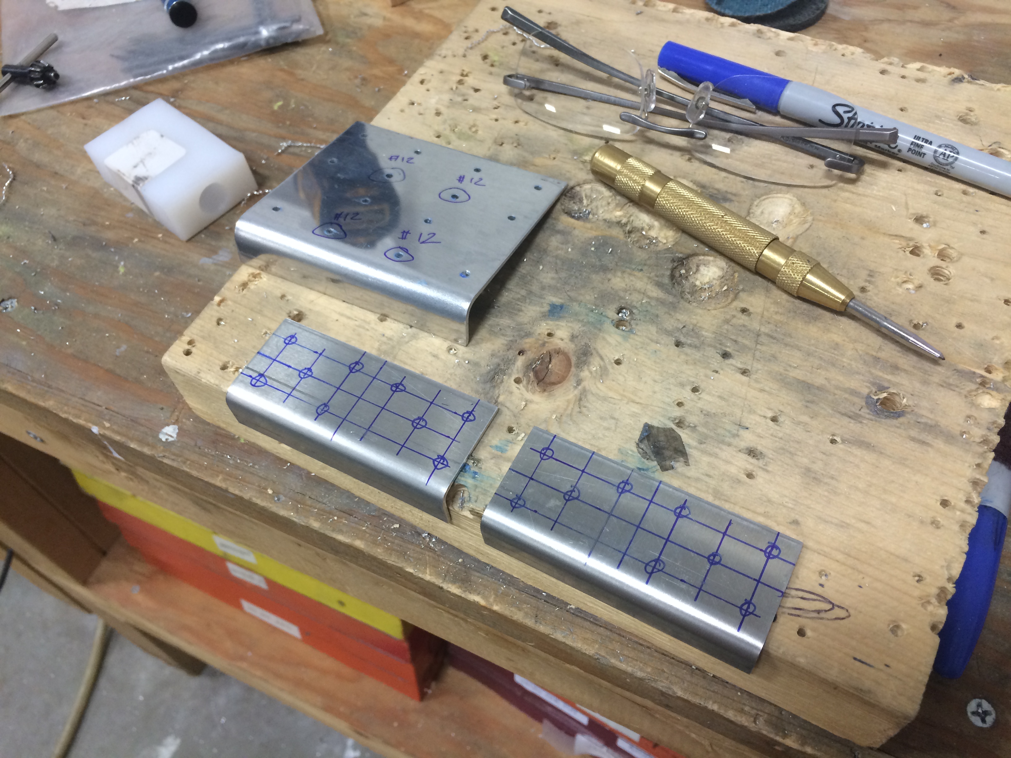
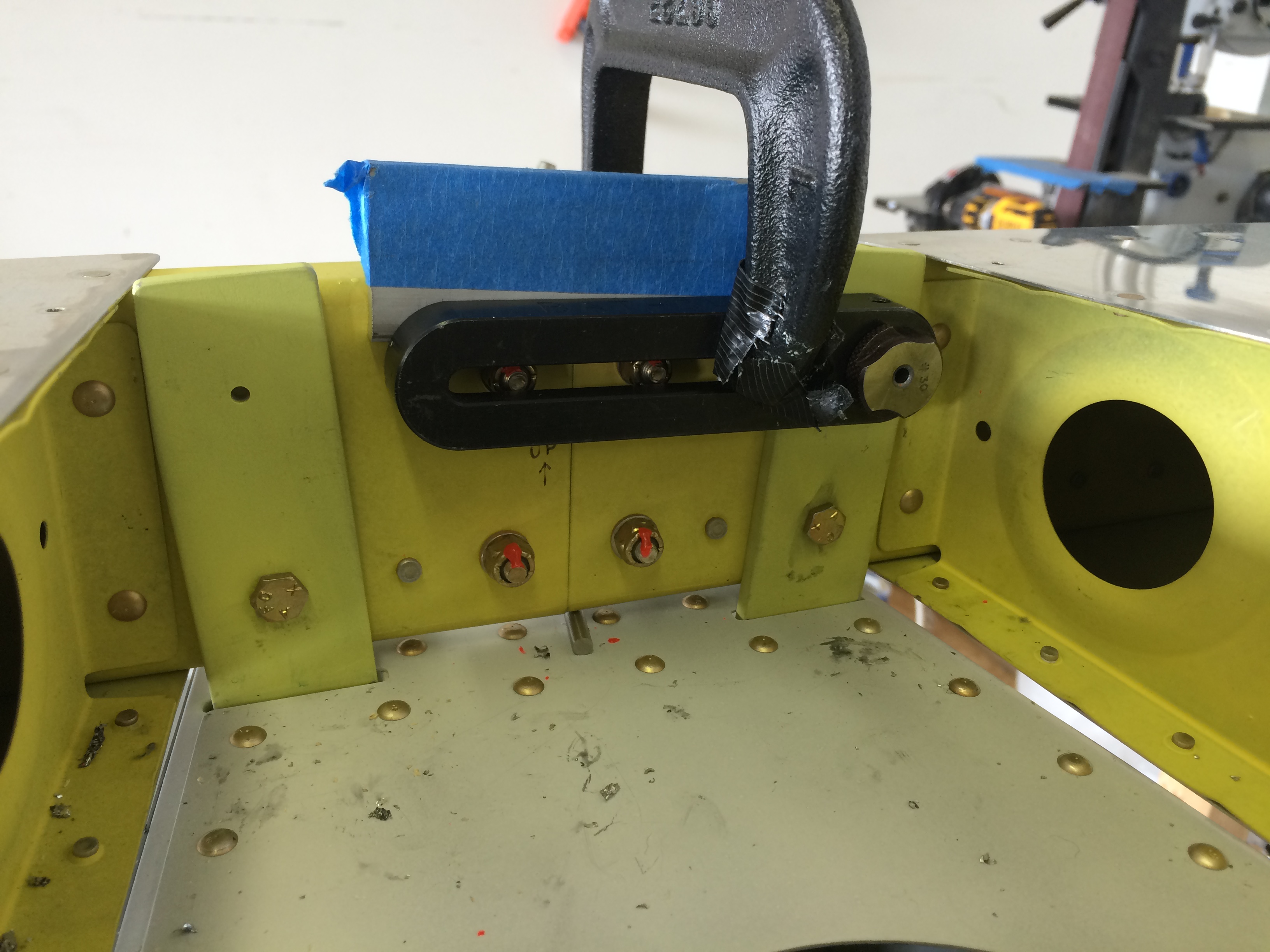
One final task before drilling to the skin and rollbar – marking hole locations for the screws that attach the fuse skins to the canopy. I borrowed a trick from Mike Bullock and used a piece of masking tape to lay out hole spacing. I laid a piece tape parallel to the skin edge at the correct edge distance and marked the location of the first and last screw holes.

Read the plans carefully here, because Vans doesn’t explicitly call out the edge distance – it’s inferred from one of the cross-sections depicted in the plans.

Rear window screw locations laid out

With the first and last hole marked, I pulled the tape off, measured the distance between the first and last holes, and did a little airplane builder math to mark the rest of the screw hole locations. After that it was an easy matter to put the tape back on the fuse and mark the holes for drilling.

One side note – regular masking tape is kinda stretchy for laying out hole spacing, so I used some 3M plastic fine-line auto painters tape I had laying around from a previous project.  This stuff worked great – it was easy to get the holes spaced perfectly because the plastic tape didn’t stretch much at all.

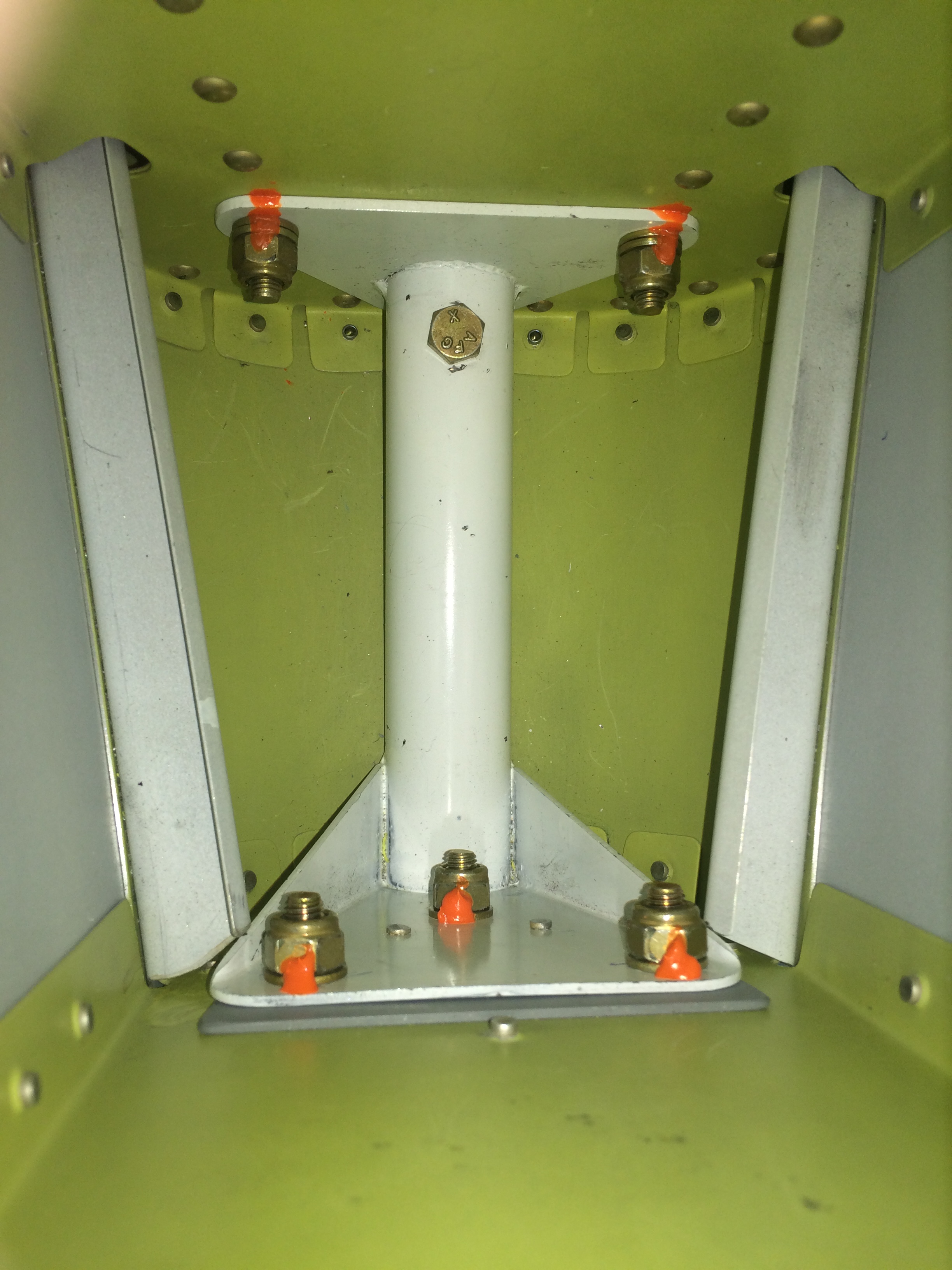
Laying out screw holes on the roll bar was easy – all I had to do was match the locations of the holes I’d already drilled for the front canopy.

Rear window drilled 1

I bribed Ellen with the promise of a nice dinner at our favorite Mexican restaurant if she’d come up to the hangar and help drill the rear canopy, which she graciously agreed to do.

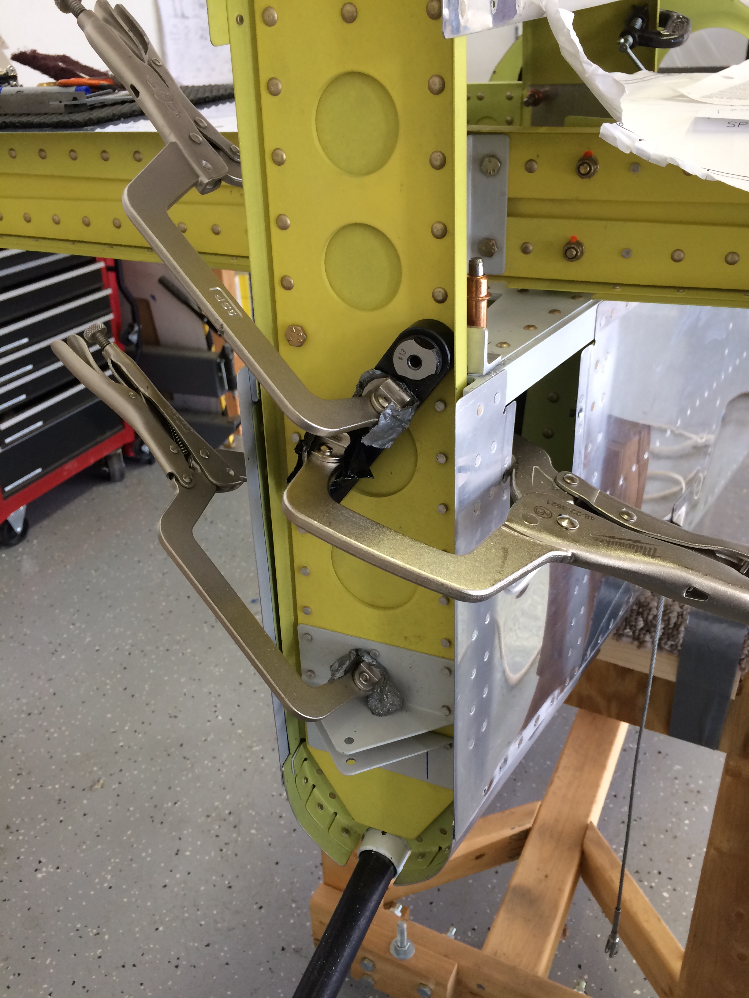
This was a piece of cake compared to the front canopy but there are a couple of tips that help improve the drilling process. First, it’s a good idea to pre-drill the fuselage skin holes with a small drill bit without the rear canopy in place; the small holes help center the tip of the 1/8″ plexiglass drill bit when match-drilling through the canopy.

And second, be careful to not drill through the rollbar with the plexi bit – this would enlarge the holes past the size necessary for a #6 tap. Use the pre-drilled holes on the rollbar to locate the holes, then drill  them with the plexi bit just deep enough to break through the opposite side of the canopy, then enlarge later to full size when the canopy is off the frame.

Rear window drilled 2

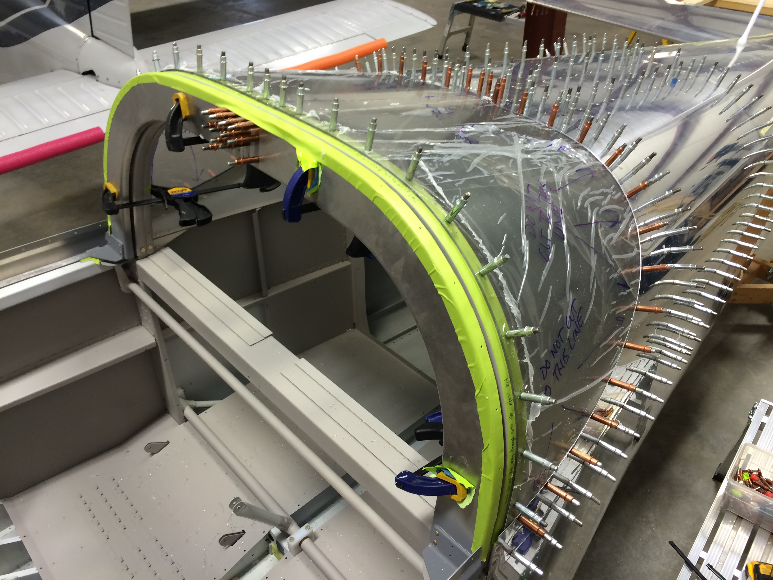
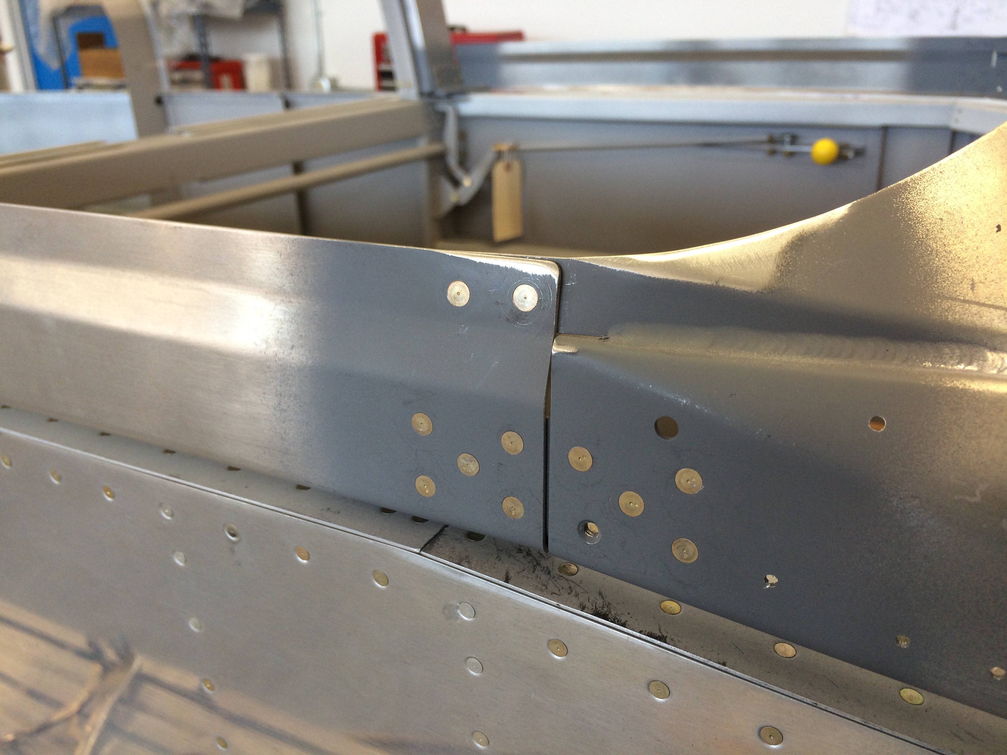
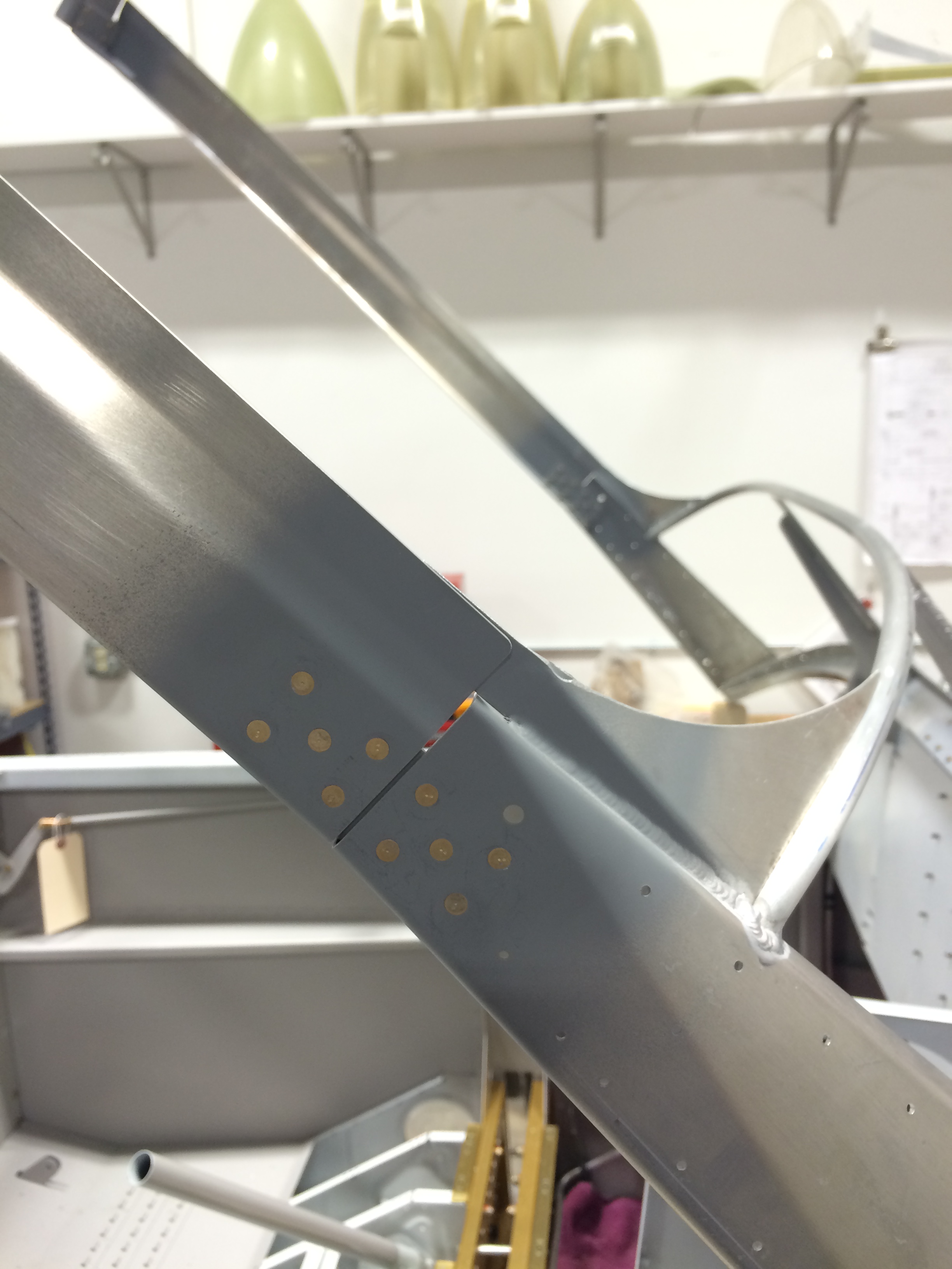
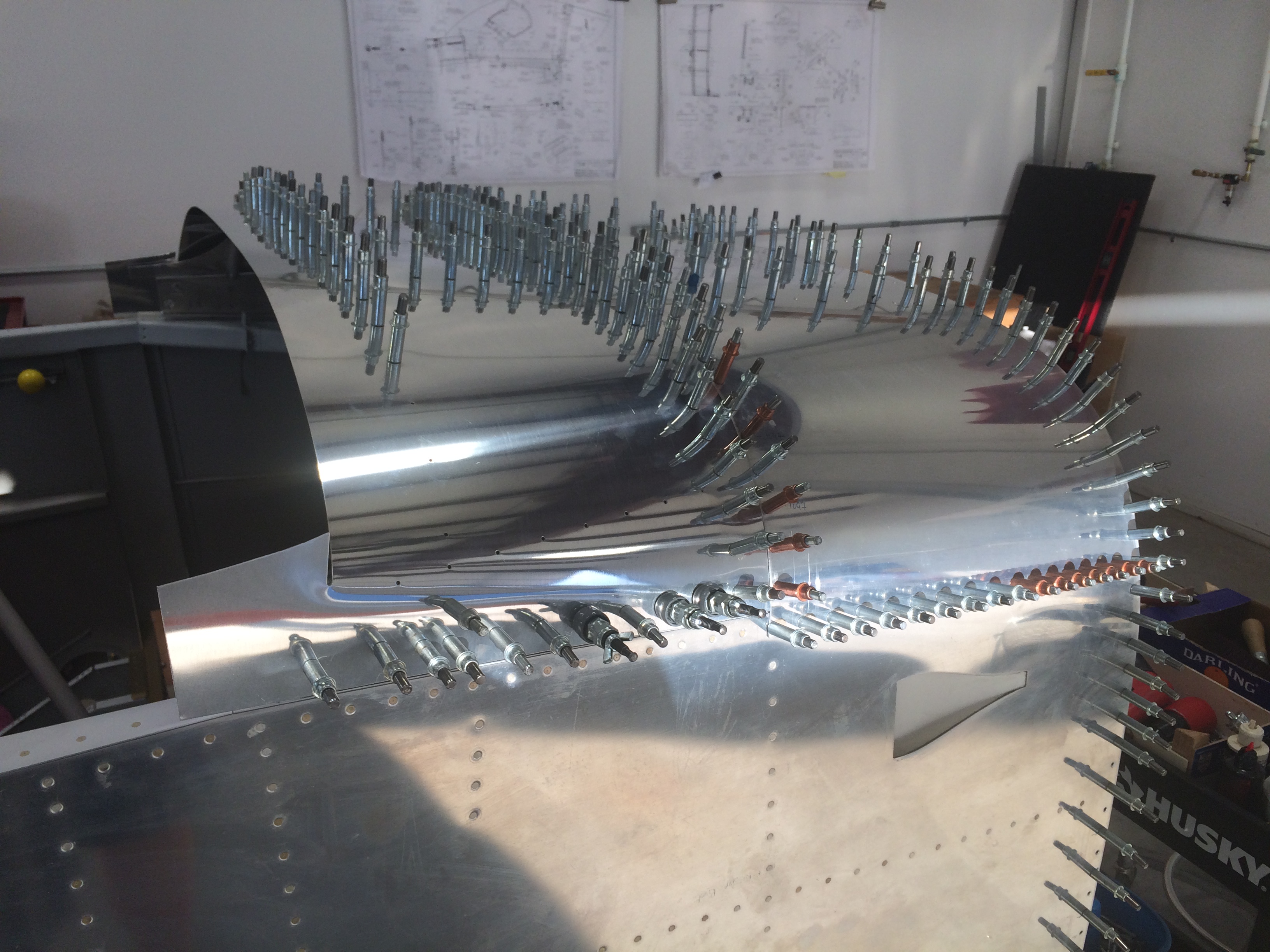
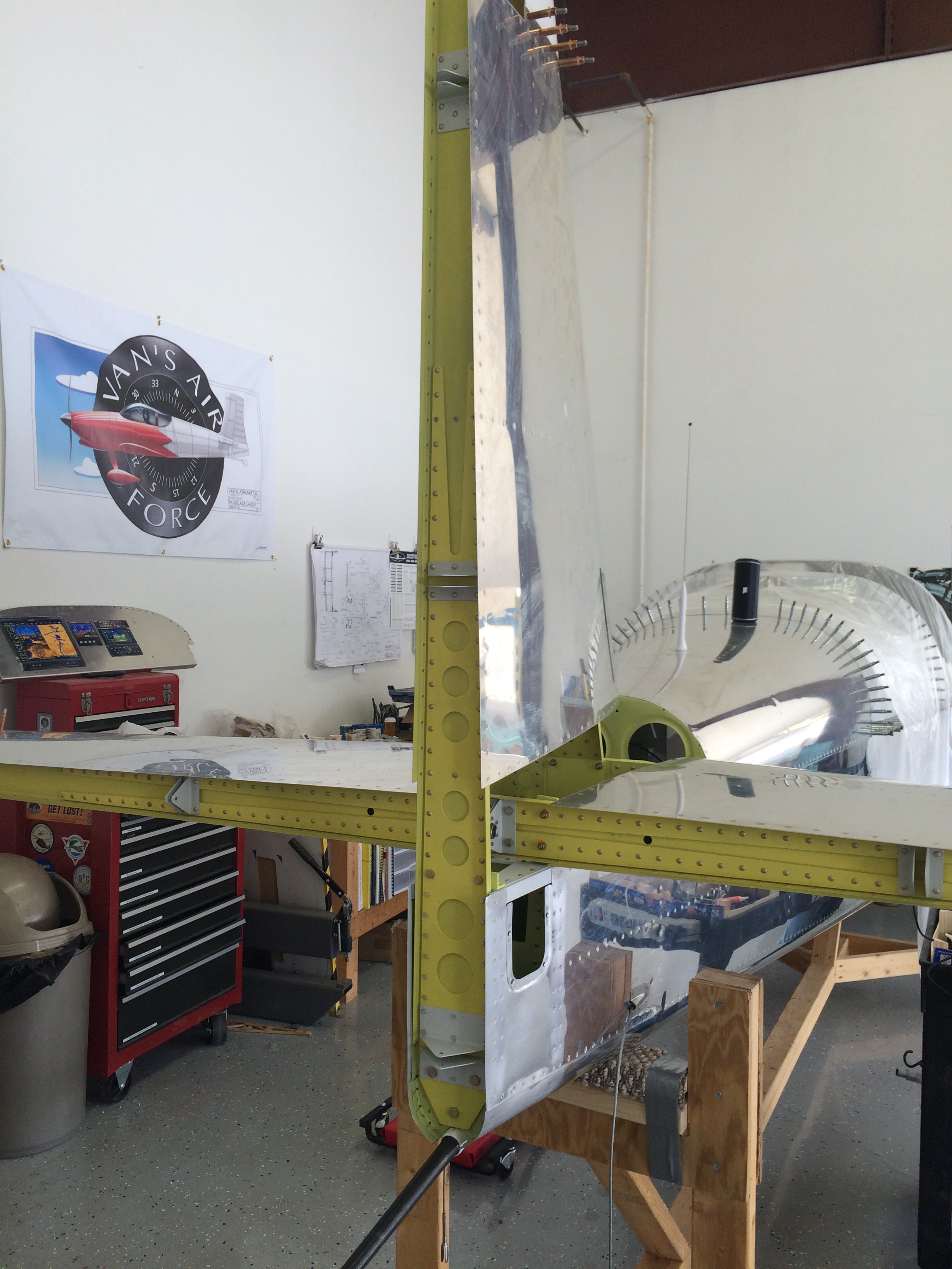
And here’s the final product after match-drilling. I still have to trim the forward edge to match the “big cut” line, polish the canopy edges, countersink the screw holes and drill them to final size, but everything looks good for now.

I won’t trim the forward edge until I get the front canopy back on the frame with the lift struts installed S.me builders say that the struts push the whole frame aft, so I don’t want to do any edge trimming until the canopy is sitting in it’s worst-case position with respect to the gap between halves.

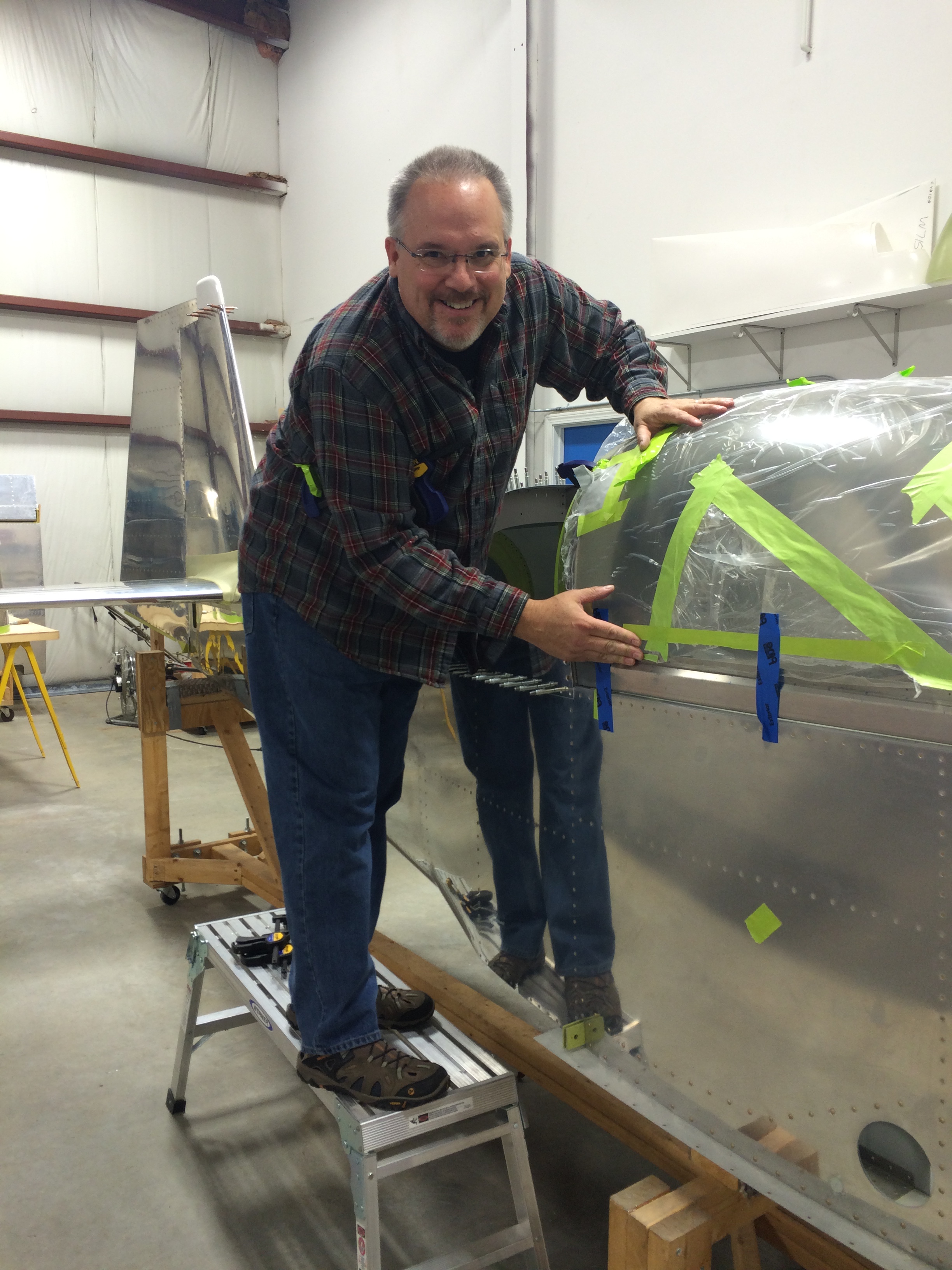
P.S. – If I haven’t mentioned it recently, I think I’m one of the luckiest builders – and really, one of the luckiest men – I know to have a wife and partner like Ellen. She’s learned to be an ace riveter, encouraged me to keep going when I’ve wanted to quit, and helped me keep perspective on the truly important stuff – and I don’t mean the airplane.

Thanks, sweetie…

Drilling the canopy

I’ve been busy over the last couple of weeks on consulting projects so I haven’t had the time to work on the airplane until this weekend. On Friday I finished adjusting the forward canopy skin to accommodate the canopy itself.

Frame drilled for canopy

Look at the little piece of green duct tape in the lower left corner of the picture above…that arrow-shaped opening is the final result of trimming the “fingers” in the skin so that the canopy sides transition smoothly to the side rails.

Canopy skin finger trimming

I spent the better part of the day laying out and pre-drilling holes that will eventually accommodate #6 screws that attach the canopy to the frame. After that Ellen and I put the canopy back on the frame, then taped and clamped it in place for drilling.

FAA proof photo 1

Here’s a pic for the Friendly Aviation Administration to show once again that yes, I’m actually building this thing…

FAA proof photo 2

Starting at the top of the canopy bow, we drilled #30 holes through the plexiglass into the frame using an Avery plexiglass bit.  We anchored the canopy down on one side and then the other by drilling and clecoing holes 6″-8″ apart, then went back and drilled the rest of the holes.

Canopy drilled to frame

This is a Big Deal…there are only a few minor adjustments left on the side skins, and I still need to trim the rear of the canopy to it’s final cut line, but those are small tasks that I can finish in a day.

Baby steps toward the Big Cut

Cutting the canopy isn’t something to rush. I read and re-read Vans’ instructions, and researched other builders’ websites, to get a good idea of how to trim the canopy without damaging it. A replacement canopy is more than $1000, so cracks are something to be avoided.

I started this part of the project a few weeks later than I wanted to…my hope was to get the canopy cut and installed in August while the temperatures are still warm enough to not keep the hangar heat turned up. Fortunately, September has been fairly warm so not too much hangar heating has been required.

Prepping the OR for surgery

I set up everything needed to start trimming.  Per the instructions, I first cut off the portions the canopy where it was clamped in place for molding.  The back of the canopy was the first to go…

The first canopy cut

…and trimming turned out to be a little easier than I thought, but some care is required to get close to the cut line marked by the tape.

Plexiglass snow

The cutoff wheel creates a lot of plexiglass “snow” particles as it works, except that this snow can be uncomfortably hot when it hits your skin. I didn’t want any of that crap in my eyes or up my nose, so I wore safety glasses and a respirator…

Even two pairs of glasses weren't enough to protect my eyes I continued the process around the sides and front.  It was a little difficult to tell where the cut lines should be, especially on the sides.

Prepping to cut the front of the canopy

With the clamp marks trimmed off, I marked a centerline on the canopy per Vans’ instructions. This is a little tough to do as it’s hard to accurately place a tape measure around the canopy.  I wound up using a piece of string pulled tight from side to side…mark  the string where it lies on the edges, then double it back on itself and you have the centerline – sort of. I don’t think it was very precise, but it also seems to be close enough.

The canopy on the fuse for the first time

There are a couple of tabs on the front canopy frame that overlap the side rails. The instructions require that the tabs and side rails be adjusted to match the curve of the canopy’s front edge, then drilled and riveted. There’s not a lot of guidance here, and it’s hard to see through the protective plastic sheeting on the canopy to tell how the curve should lie. So…I took my best shot.

Adjusting the canopy rail bends - holes countersunk And then riveted the tabs…

Canopy rail fitted and riveted on the right side

…and everything looks good for now.

Canopy marked for cutting

I’m reasonably happy with the canopy fit, so I started marking the line across the rollbar where the canopy will be cut into forward and rear sections. This process is not-really-affectionately known to builders as making The Big Cut.

Canopy forward edge

I worked on the front edges a bit to get them to lay down a little more accurately on the front canopy skin, but from what I’ve seen on other builders’ websites, you can do all the work on this area you want but once the canopy is drilled in place, some gaps will open up.  So I’m going to get it close and not worry about it.

Canopy in place for cutting

I hoisted the canopy onto the sawhorses and plywood, and used some long 2x4s to move it off the work surface They also gave me something to clamp some smaller pieces of 2x4s as side supports that keep the canopy from spreading as I cut it.

As other builders have also done, I laid several pieces of masking tape along each side of the cut line to help guide the cutoff wheel. I was skeptical that this would work, but it did and very well too.

I took a few deep breaths, and started cutting…

Starting the Big Cut

…and the process went very well. I used tongue depressors to keep the canopy separated  as I worked my way along the cut line.

The Big Cut is complete

And here’s the completed cut…what a relief to have this done.

Forward half of canopy on the frame

It’s a lot easier to move the canopy on and off the fuselage. I’ll be doing a lot of that as I finish fitting it to the frame and then drilling the attach holes.

An engine is born

I stopped by Tim Hess’s engine shop today to see major parts of the engine coming together as Tim joined the case halves.

Engine case halves

Just getting to this point involves a lot of work – Tim has already balanced the major rotating components, checked tolerances on the bearings (and in some cases replaced ones he wasn’t happy with) and flow-matched the cylinders.

Case halves bolted together

One of the reasons why I didn’t want to do this myself – the first time, at least – was that there are a lot of things that appear to be easy but can easily be done incorrectly, like applying the silk thread that’s used to seal the case halves, or laying down lubricants and sealants on the crank and cam.

Case halves on the stand

I’m very happy with how everything is coming together on this part of the project. Later this Fall or Winter, it’ll be time to hang this thing on the fuselage.

A riveted frame

Got just enough time in the hangar tonight to rivet the canopy frame together and put it back on the fuselage. I left the primer to dry for a couple of days, and the Nason etching primer I used was tough as nails!

Frame riveted before installationFrame rivets

There’s an small and easily fixable mistake in this pic. Can you spot it?

2015-08-27 20.53.47

And now it’s time to start trimming the canopy…yikes!

More fun fitting the canopy frame

More fun with the canopy this week as I spent several hours adjusting the fit of these parts that form the rear canopy frame.

The distortion caused by both the flanges and L-shaped bend in each frame half takes some work to make them fit adequately. The instructions tell builders to flute these parts to remove the distortion, but at least one of mine was just about right out of the box and really didn’t need fluting. The other one doesn’t fit quite as well, but I’m resisting the urge to flute it because (a) the fit isn’t that bad and (b) I tried fluting a spare frame part I had and it was a PITA.

In this picture the frame halves are not perfect, but they’re getting close to being good enough.

Rear canopy frame

The side rails were an easier fit, because Van’s had already done all the bending and metal shrinking needed to make the side rail curve fit the longeron bends I worked so hard to perfect several years ago.

Canopy side rails

The side rail flanges don’t quite conform to the aft frame parts, but I think they’ll pull into shape pretty well when they’re drilled and clecoed.

Side rail to canopy bow fitI still have some parts to fit to the frame, so stand by for more words and pictures.

Canopy splice platesLaying out the side rail and rear canopy bow splice plates. Note that the side rail doublers at the bottom have one hole that isn’t marked to be drilled – that’s because Van’s conveniently forgot to mention in their plans that there’s already a hole through the canopy frame in this area, and if you drill the hole in the splice plate it won’t line up with the frame hole.

2015-08-20 19.55.46

Ok, so I said I wasn’t going to flute the rear frame – but I did, and it actually came out pretty well. Here’s the side rails and rear frame clamped into position.

Fitting the side rails

The little cheapo Harbor Freight clamps are holding on some strips of 0.032″ scrap that simulate the canopy side skins. The side rail is correctly placed when the bits of scrap lie flush with the side of the fuselage.

Side rails drilled to F-631s

Sharp-eyed RV builders will see that I’ve inserted a shim between the side rail welded angle and the F-631 rear frame half.  The fit wasn’t quite what I wanted, so when in doubt – shim it out. After that I couldn’t think of a good reason not to drill everything, so I did.

2015-08-21 16.07.25

These plates splice the side rails to the forward canopy frame, and drilling them was a bit of a pain. It’s vital to uncleco and peel back the forward canopy skin, as nine of the ten holes in this part don’t go through that skin and drilling through it would be uncool.  You’ll see one hole (bottom row, second from the right) that doesn’t quite line up. That hole *does* go through the skin and frame, and once the other holes were done I back-drilled this one using the forward frame as a guide.

2015-08-21 17.10.48

And here’s everything drilled and clamped to make an almost-complete canopy frame. As my friend Jim would say, this is one of those moments of Big Visual Progress. They kinda sneak up on you after a lot of tedious fitting and drilling, then suddenly everything comes together…et voilà, it looks like a real airplane part.

I hated to take everything apart, but there are a couple of small parts left to fabricate and fit to the frame.

Wedges

Look carefully in the pic above, just under the two leftmost copper clecoes, and you’ll see a thin aluminum wedge filling the gap between the side rail splice plate and forward canopy frame flange. Scroll back a couple of pictures and you’ll see the unfilled gap.

I had to make two of those – one on each side of the canopy – and each one took about an hour of cutting, sanding, filing and fitting.  What fun…but now I can take the frame apart  and debur, countersink and prime everything before riveting. And that, in turn, means it’ll soon be time to work on the plexiglass canopy itself.

Tweaking the canopy frame

After drilling the canopy hinges, I had to do some filing on the seal support angles so that the canopy would open without rubbing on them. Not really much to see, because the seal support angles are hidden in this pic.  But the canopy frame now pivots the way it should, and that’s worthy of a picture.

Tweaking the canopy frame

A week of airplane building

A solid week of airplane building…missing Oshkosh, but getting a lot of work done.

I’ll be adding text here when I get the chance.  Right now it’s a holding place for pictures so I can document what I got done…more to follow.

Support for brake line Adel clamps

Matco PVPV-D parking brake and doubler –

Parking brake valve and doubler

Doubler plate taped to firewall

Temp fitting the parking brake doubler

Testing out my plumbing idea.

Valve taped into place

Parking brake taped into place to check lines

2015-07-21 17.34.33

Parking brake valve crossover lines installed.

Brake lines protectedBrake lines protected against abrasion with spiral wrap. Somehow it makes them look more “finished.”

Canopy latch parts painted

Canopy latch parts painted

Canopy latch installed

Massaged the canopy frame, then reinstalled skin. Flush dies in the pneumatic rivet squeezer helped work out inadvertent creases in the skin, and a flush set in the rivet gun helped with the frame.

Canopy taped for final drillingCanopy taped in place with spacers installed for final fame drilling.

Riveting the canopy frame 1

Riveting the canopy frame. It’s about time I put that 12″ double-offset back rivet set to good use.  It sucks up a lot of kinetic energy, though…90 PSI on the compressor just to get the rivets to set.

Riveting the canopy frame 2

Another picture of riveting the canopy frame

Frame riveted

Here’s the canopy frame riveted, with the skin reinstalled, and fitted back into place on the fuselage.

Canopy frame fitted and ready for drilling

Final fit before drilling the hinge brackets

Canopy frame side fit

Fit is pretty good on the right side.

Hinge hooks drilled, bushings insertedCanopy hinges drilled and bushings installed


The tail end

Over the last month and a half I’ve been slowly working on getting the horizontal and vertical stabilators attached. There’s nothing terribly complex here, but there are some places where access for drilling holes and installing fasteners is tough.

Starting with the horizontal stabilizer, I aligned it with the fuselage per plans and drilled the inboard holes that attach the forward spar. Access isn’t so good here for a regular drill so I used the angle drill and my technique wasn’t great…despite using an undersize drill bit, the holes wound up oversize.

2015-04-04 14.30.48

The outboard holes were easier to drill, but required some extra care to ensure that edge distance was maximized on the stabilizer, fuselage longerons and bulkhead. I drilled these holes initially to #30 to check alignment, then final-drilled them to #12.

2015-04-04 14.41.53

I talked with Vans about how to handle the oversized inboard holes. Their recommendation was to upsize the holes to 0.25″ and use AN4 fasteners. Before I did that, though, I wanted to try a first-oversize close tolerance NAS6604 fastener that’s approximately 1/64″ larger than a norman AN3 fastener. That would preserve 2D edge distance on the hole. I reamed the oversize holes to accommodate the NAS6604 bolt, and the bolts were a perfect fit – problem solved.

2015-04-18 15.57.13

With the forward horizontal stab spar drilled to the fuse, I clamped the rear spar to the fuselage attach bars. If you look carefully, you’ll see the business end of a 3/16″ punch between the rear spar and fuselage aft deck. That 3/16″ gap establishes proper incidence for the horizontal stab relative to the fuselage.

With that gap set, I clamped the fuse bars and rear spar together, and using my Brown Tool drill block, drilled the four #12 holes that hold the assembly together.  I use the drill block whenever I can…it works great for getting nice, clean, straight holes.

2015-04-19 18.20.47

Here’s everything bolted in place. Look carefully and you’ll see the dimpled heads of the NAS6604 bolts on the front spar.

2015-04-19 18.20.22

Here’s the HS stab in place. It’s been sitting in storage for ten years…and now it’s part of the airplane. Cool.

The next step was to attach the vertical stabilizer.  There are several steps in this process, and a couple of them were somewhat tricky. Just getting the vertical stab aligned correctly was a challenge – it was tough to get everything clamped in place firmly enough that the vertical stab didn’t shift while measuring its alignment relative to the horizontal stab.

I had already fabricated the upper stab attach bracket and match-drilled it to the fuselage – with the stab aligned I used my trusty drill block and match-drilled the attach bracket to the stab. All those vise-grip clamps I’ve been collecting sure came in handy.

Drilling upper VS attach

Upper VS attach bracketAfter the upper attach bracket was match-drilled, I fitted the angled attach plate that connects the vertical and horizontal stabilizer forward spars.

Drilling VS front spar 1 Here I’ve already match-drilled the plate to the horizontal spar – those holes will be opened to #12 – and I’ve started drilling the plate to the vertical spar as well. I had to insert a 0.020″ shim between the plate and spar to improve the fit.  The plans tell you to anticipate this, and have dimensions for fabricating a shim if one is required.

Drilling VS front spar 2

I used the angle drill sparingly on these holes. Some of them didn’t get final-drilled until I removed the vertical stab for priming.

Rear VS attach

Here’s the vertical stab’s rear spar primed and bolted into place.

Tailwheel fitting bolted and torqued

I neglected to take many pictures of the measurement and drilling process for the lower three bolts – they secure the vertical stab lower spar and tailwheel aft attach bracket to the fuselage.

The measurement process was a little tricky – edge distance has to be maintained on the tailwheel bracket and the vertical stab spar, but they’re on opposite sides of the aft most fuselage bulkhead so it’s impossible to directly measure edge distance. The only way I could get this done correctly was to establish a series of reference points for the tailwheel bracket measured from the fuselage sides and aft deck. Those reference points allowed me to project the location of the tailwheel bracket onto the rear side of the aft fuselage bulkhead.

With the vertical stab clamped into place, I was then able to pick hole locations that met all of Vans edge distance criteria. After that, drilling the holes was a piece of cake.

Tail in place

Here’s the vertical stab bolted and torqued into place…very cool.

Tail attached from the rear

Another pic? Sure, why not…

Nice tail!

And I couldn’t resist temporarily installing the rudder…it’s been waiting a long time to be on the airplane!

Getting a look at our engine parts

Today I visited Tim Hess to look at the Superior XP-360 parts that Tim will be assembling into the Mighty RV’s engine.

Tim and the engine parts cart

I was really impressed with Superior’s parts kit…everything organized very neatly.

Dave's crankcase

It’s almost a shame to paint this beautiful gold-alodined crankcase, but Ellen and I have agreed that the crankcase will be painted red.

Dave's cold air sump

Here’s the Superior cold-air sump. I was impressed with the casting and milling, and Tim pointed out several areas where the Superior sump is better than the stock Lycoming part which embeds the intake tubes in hot sump oil.

One of Dave's cylindersAnd here’s one of the cylinders.  These aren’t going to be painted…they’re just too nice to cover up. Superior makes very nice parts…