The website is woefully overdue for an update, so here it is. Rather than try to parse out everything that I’ve done in the last month into a series of individual entries, I’m throwing it all at you in one chunk. So…grab a beverage and settle in.
After finishing basic construction on the rollbar, I did all the usual prep work – deburring edges and holes, and countersinking where necessary. Unfortunately, practically every rivet on the rollbar assembly is flush so there was a lot of countersinking to do – and just about all of it was on curved surfaces which made it really difficult to use a countersink cage. Taking a cue from other builders, I decided to go without the cage and do the work freehand – which wasn’t as difficult as I had feared. The only downside is that it’s a very tedious process – countersink a little, test-fit a rivet, repeat until done – then move on to the next hole.
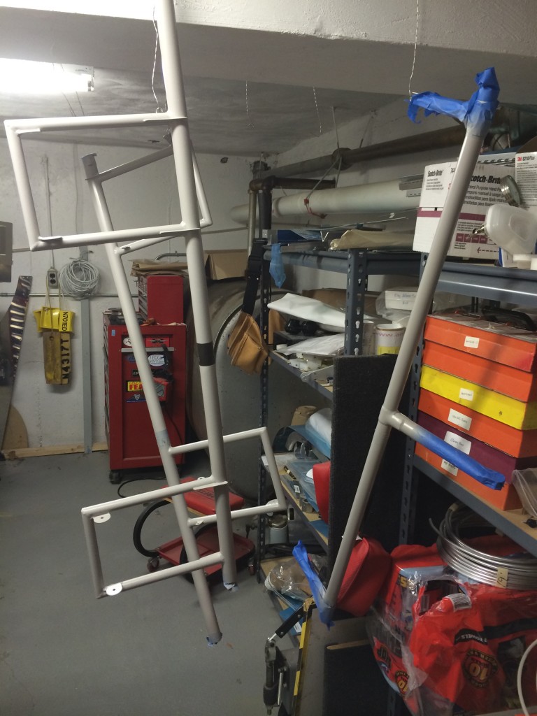
There’s not much to say about priming…the only difference with the rollbar is that I decided to use the industrial-strength aerospace epoxy primer that I’ve pretty much stopped using. The reason is that the rollbar apparently channels a lot of moisture from rain, and a good fluid-resistant primer is worth the hassle to protect the parts.
I neglected to take any pictures of the prep and priming process…sorry.
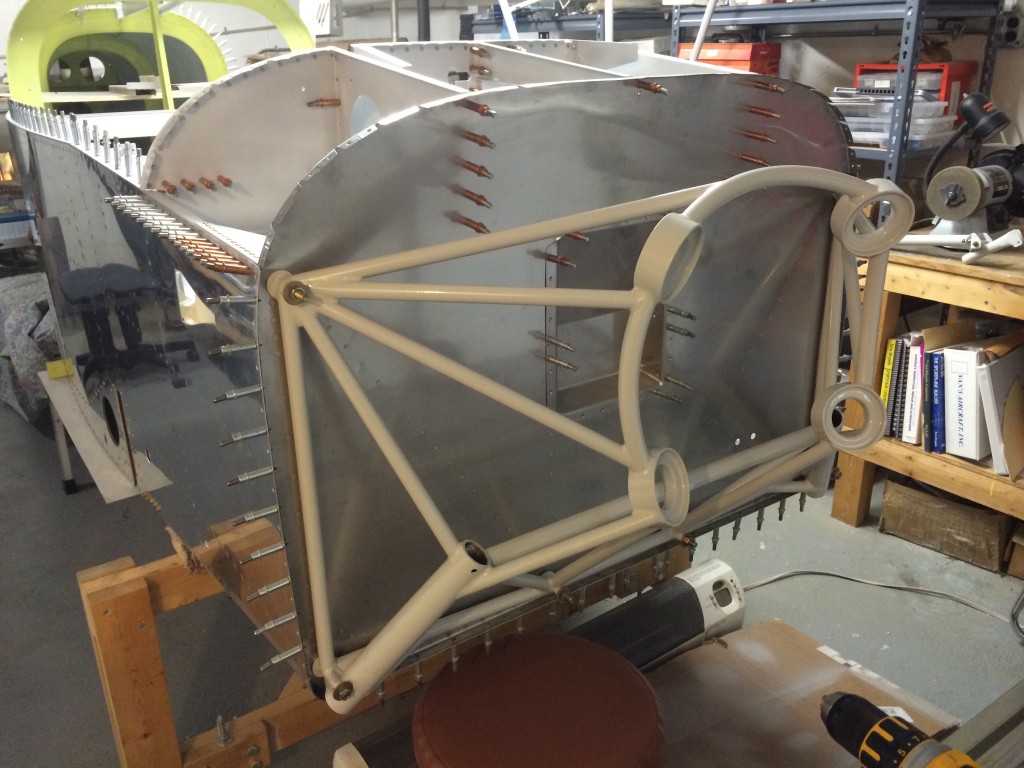
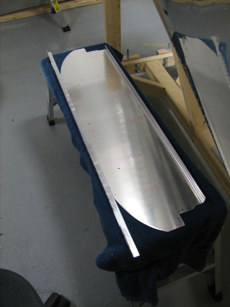
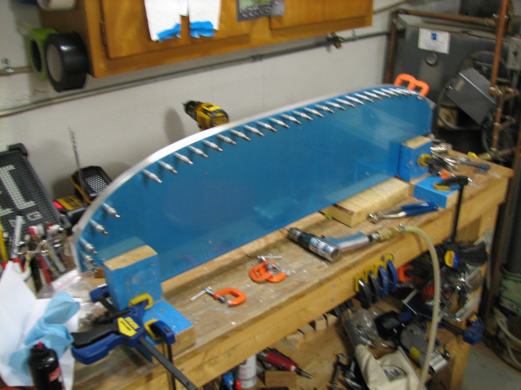
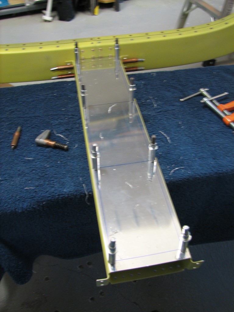
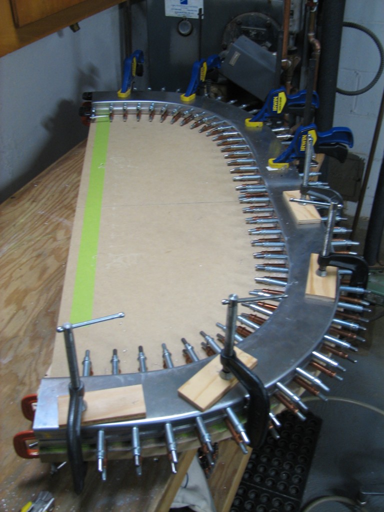
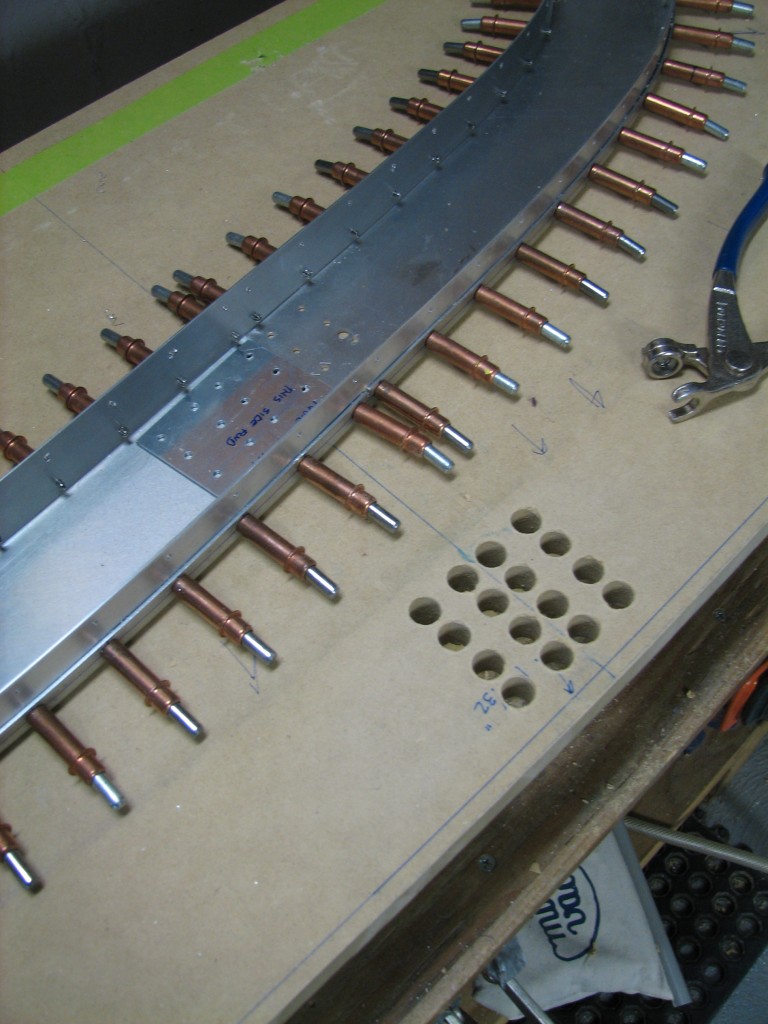
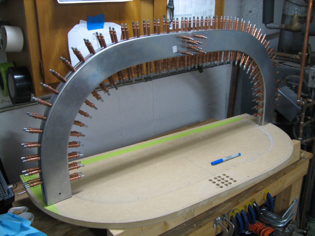
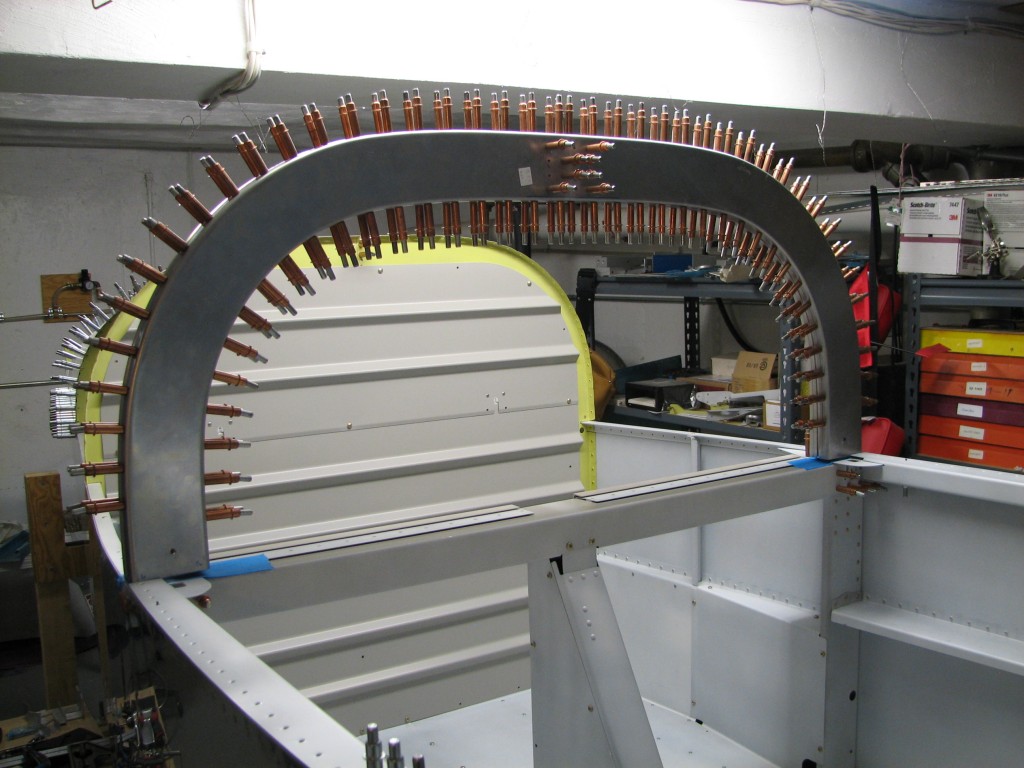
After priming, I started riveting. Here’s the front half of the rollbar riveted in assembly with the top and bottom straps.
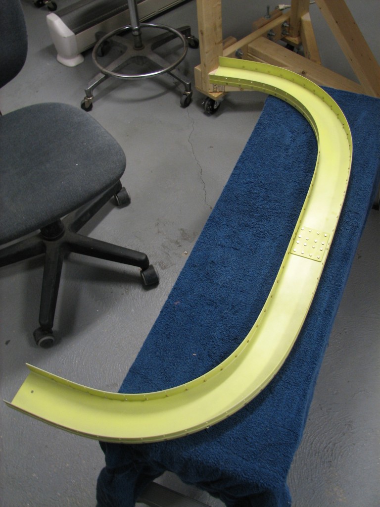 If you’re an RV builder and working on this part, one bit of advice I’d offer is to clamp the rollbar back onto your work surface when you rivet the straps. Even though the parts were (hopefully) match-drilled on a flat surface, some twist can creep back in if you’re not careful. Fortunately, I wised up when riveting the back half of the rollbar…
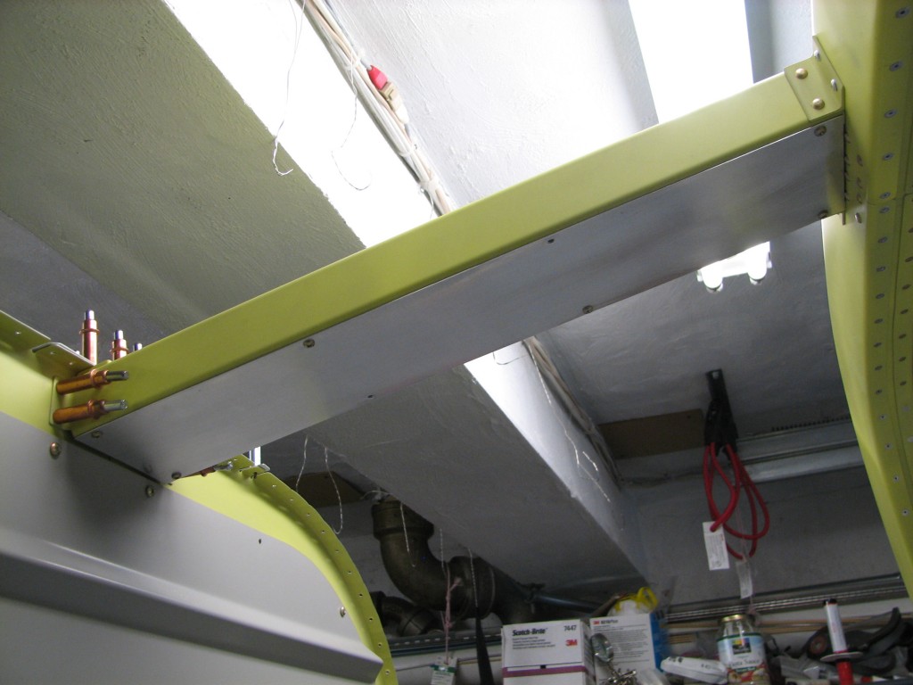
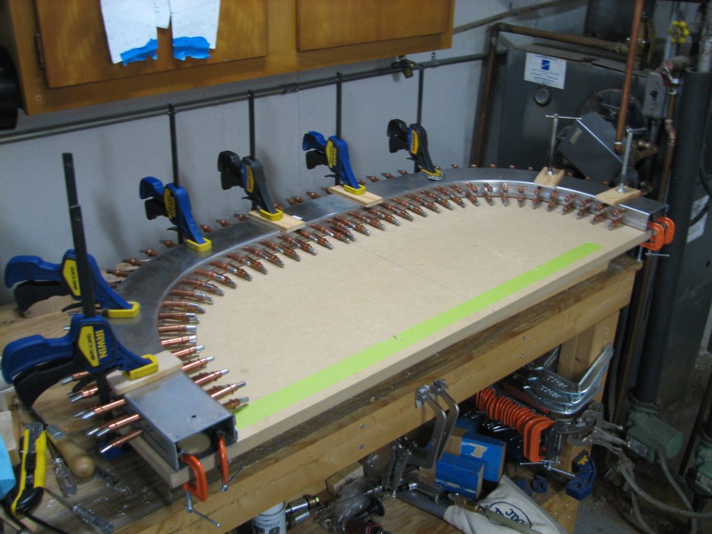
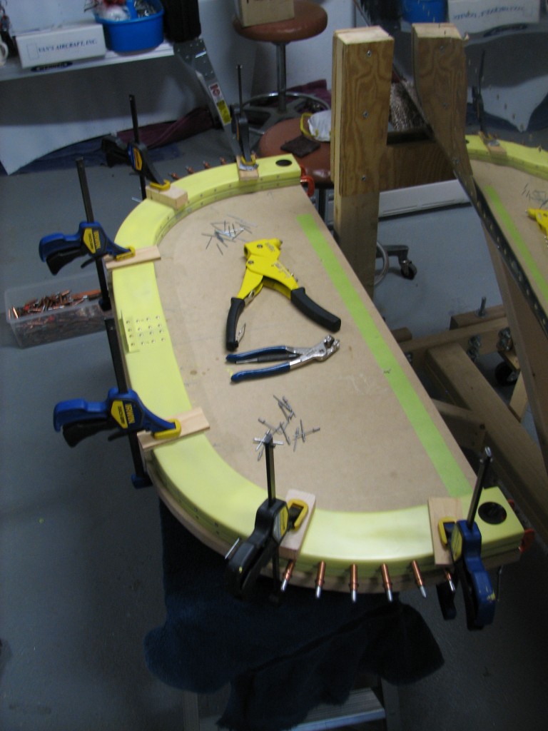 Here the aft half of the rollbar is pop-riveted in place. I had hoped to use a borrowed hydraulic rivet puller, but it didn’t work and in a fit of impatience I used a hand puller on all 80 pop rivets. That was a mistake, because since then I’ve had had a sincere case of repetitive strain injury, AKA tennis elbow, in both arms. If you haven’t riveted your rollbar yet, do yourself a favor and get a hydraulic puller. Your arms will thank you.
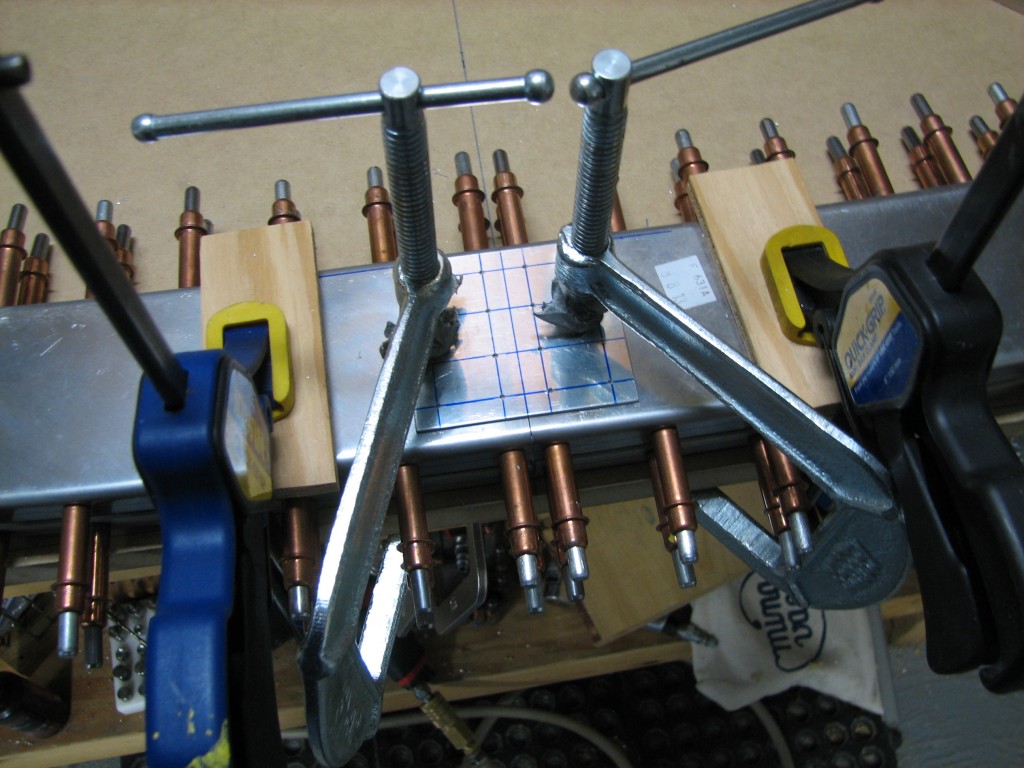
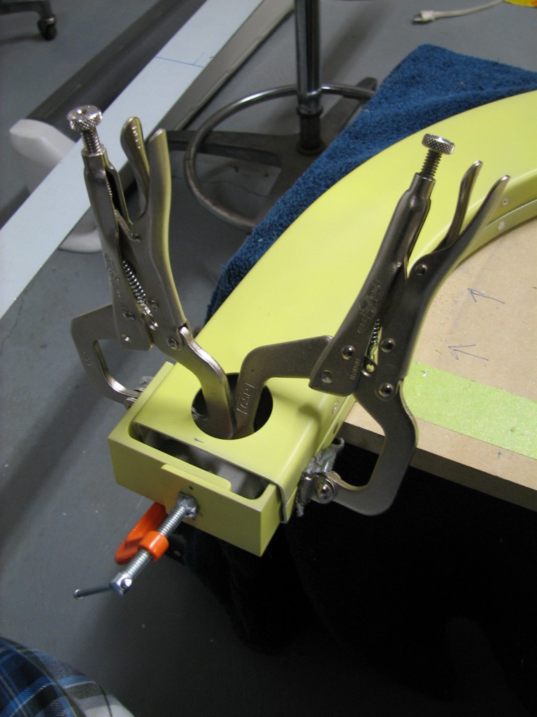 The brackets which hold the rollbar to the fuselage are fitted to each other by clamping them to the rollbar ends, then match-drilling two keeper rivets on each pair of brackets – thus setting them at the proper width. Nothing too difficult here.
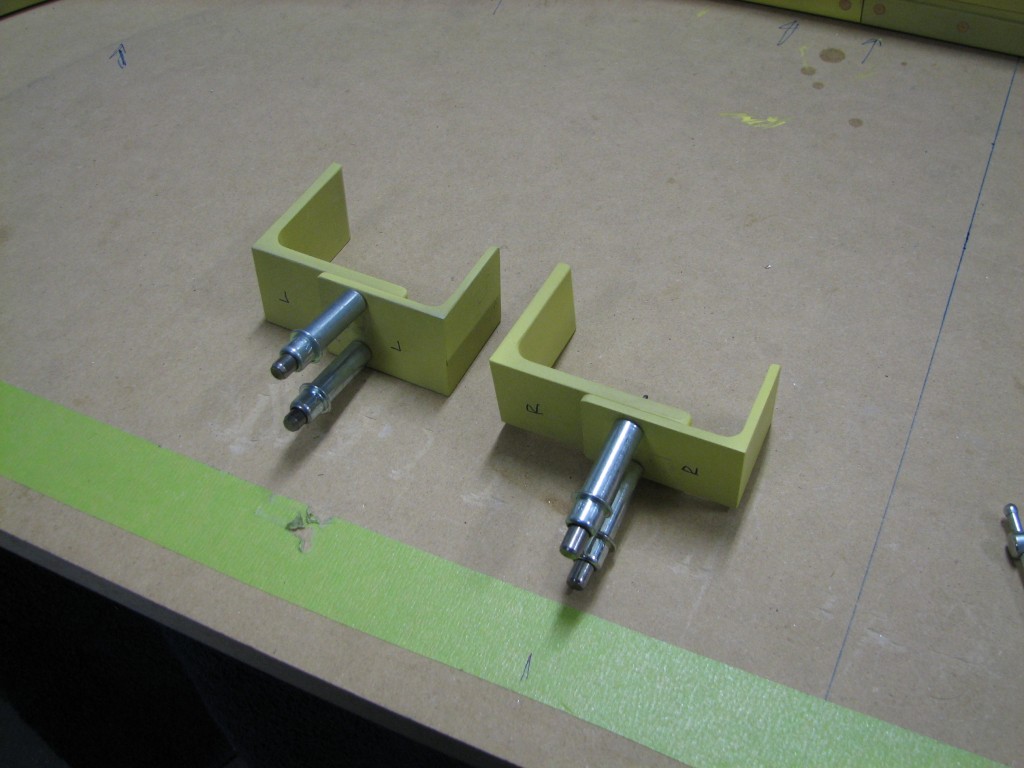 After countersinking, I riveted the brackets together. That’s all I can say about that.
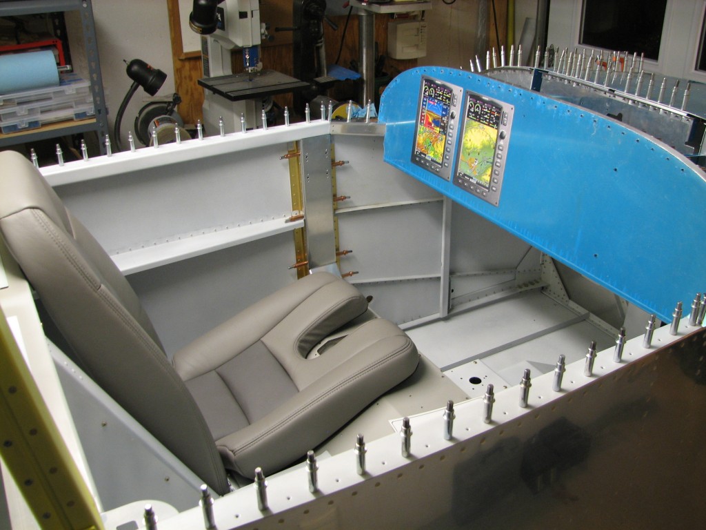
However, there was another gotcha lurking when I started fitting the brackets to the fuselage, as there was some obvious interference with the F-705 seat back support angles. From looking at other builders’ blogs, I was anticipating this problem.
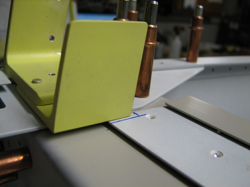
I marked out the offending areas and broke out the Dremel tool. I didn’t want to damage the F-705 bulkhead, so I drilled out several rivets from the seat back supports and elevated the parts needing a trim.
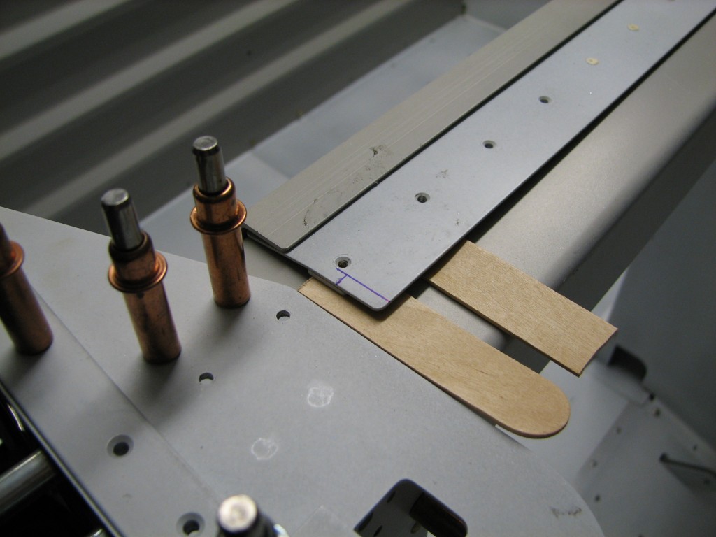
Dremel tools can be tricky if not used with a firm hand, but this little bit came out fine.
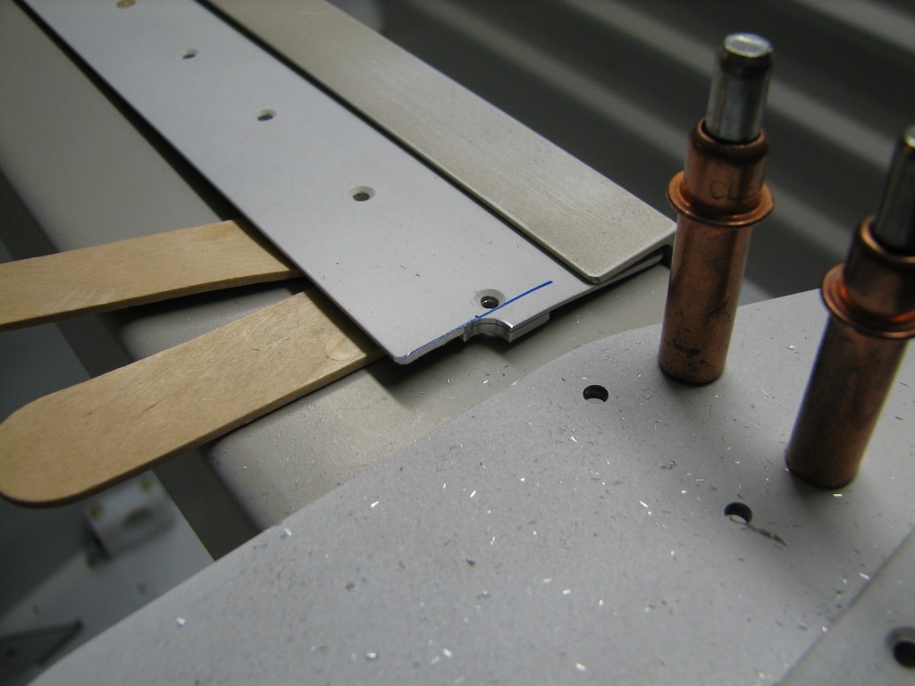 A little scotchbrite and a few squeezed rivets later, everything fits fine.
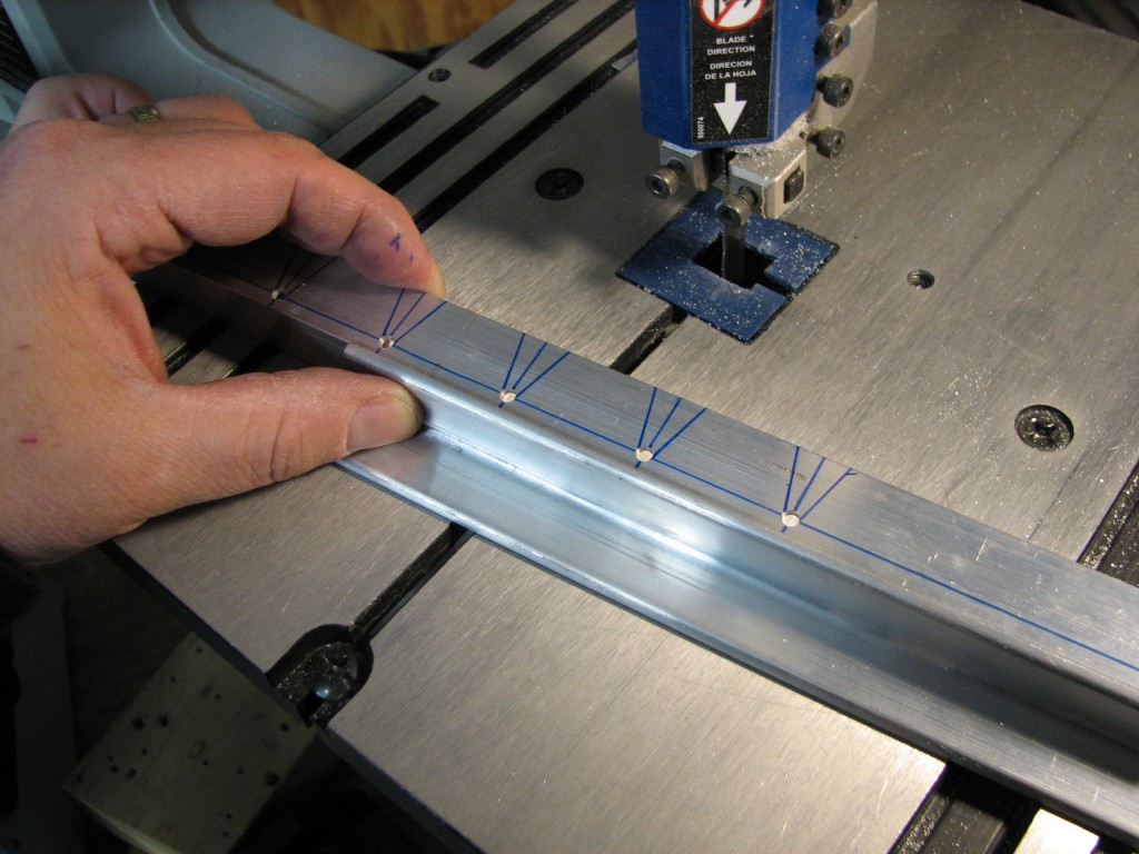
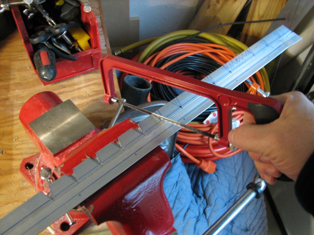
Another side task was trimming the rollbar assembly ends so that they fit over the attach brackets. Once again, the Dremel tool did the majority of the work followed by files and Scotchbrite.
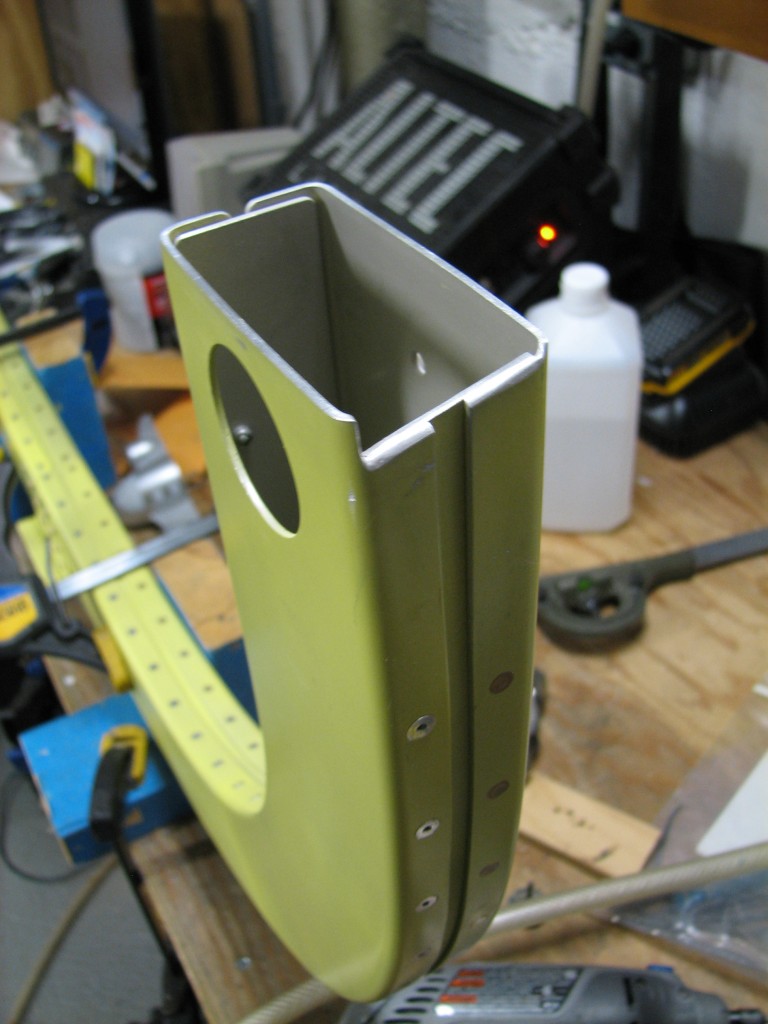
The plans and instructions don’t give a lot of guidance on how to make this cut, so I did it iteratively – trim, test-fit, trim, repeat. From reviewing the plans, the brackets appear to be positioned such that the aft sides of the rollbar are at or slightly above the F-718 longerons, so that’s how I did it. The end result looks like this…
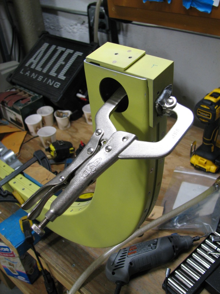
The most tricky part of the rollbar mounting process is working out precisely where the attach brackets are installed on the fuselage. Van’s instructions leave a lot to be desired here…there are full-size depictions of the installation in the plans, but not so many dimensions – perhaps that’s because at this point in the construction process fuselage dimensions vary slightly from builder to builder. So, I spent a fair amount of time researching the best way to locate and fit these brackets. Big thanks go to Mike Bullock and Bruce Swayze for excellent coverage of this process in their websites.
In the end, I chose to use a combination of methods to get the job done. The plans indicate that the rollbar’s forward face is aligned with the forward ends of the F-770 turtledeck skin where they abut the canopy. With the mounting brackets clamped to the rollbar, and the forward turtledeck skin clecoed in place, I clamped a long piece of AL angle against the F-770 skin and used that as a reference to mark the location of each mounting bracket.
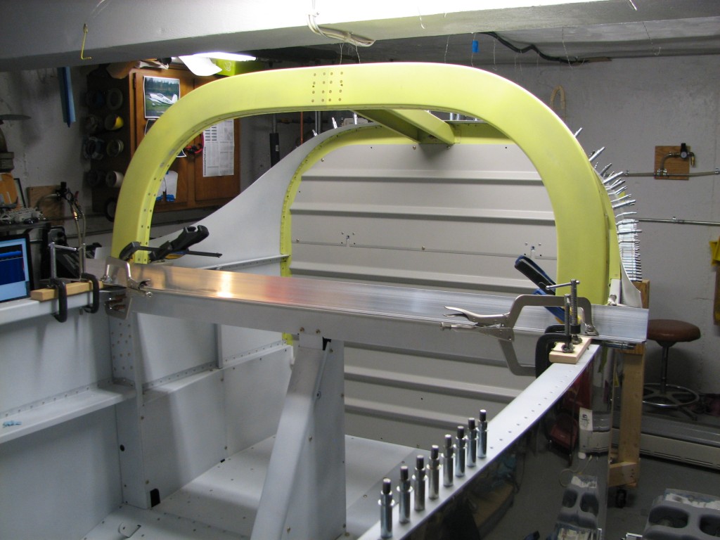
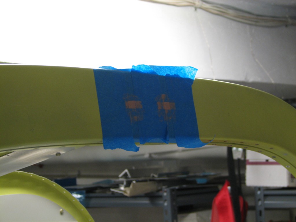
There’s no way to clamp the brackets in place on the fuse with all the other clamps in the way, so I marked the bracket locations on strategically-applied masking tape – like this…
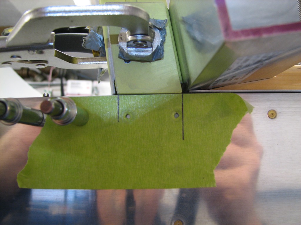
With their positions marked, I removed the brackets and repositioned them on the fuse and held them in place with clamps.
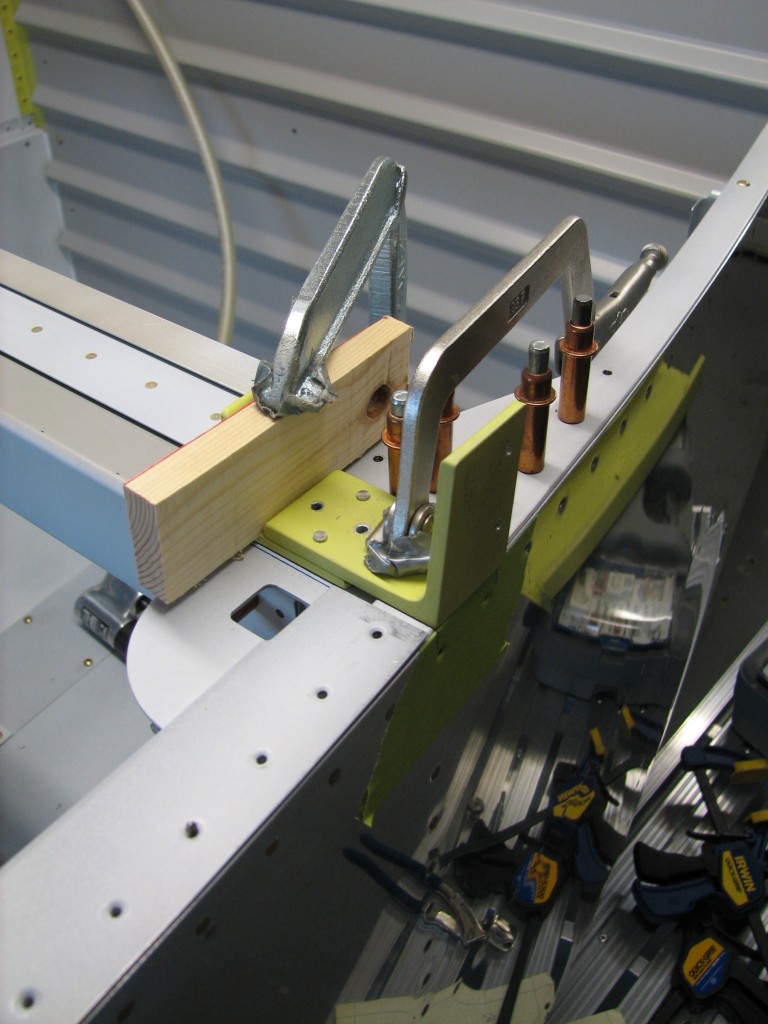
It was easy at this point to match-drill to #30 the brackets through the entire F-705 bulkhead, then enlarge the holes to 1/4″ for AN4 bolts…
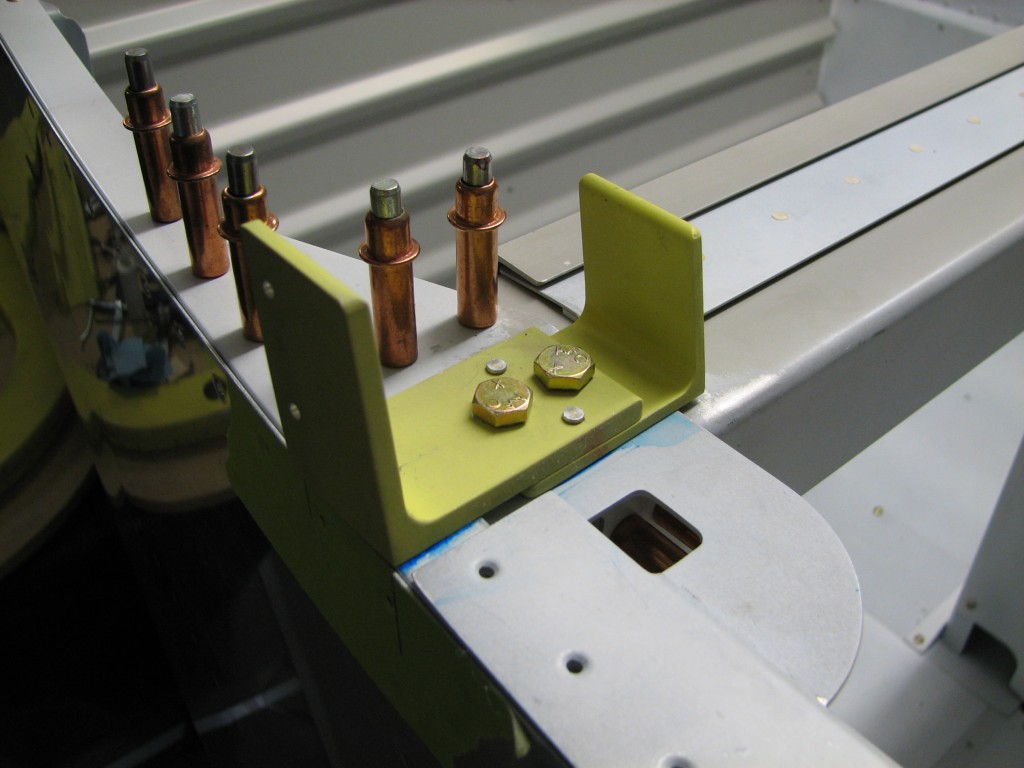
Once the brackets were clamped in place, I did a little fancy measuring to make sure the top of the rollbar was at the right height when measured from the longerons. The AL angle made that easy, as the angle vertex rested right on the longerons.
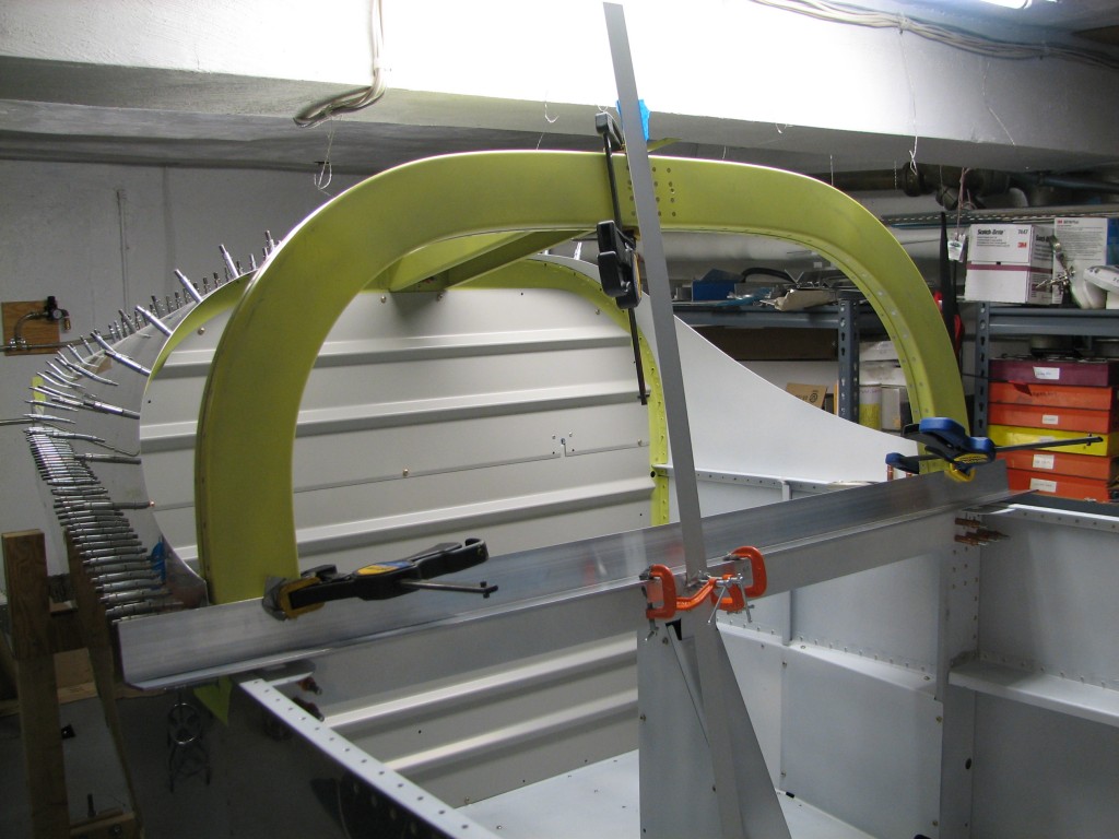
All those educated guesses on what the plans really mean, and all that nit-picky measurement when fitting and assembling the rollbar really paid off – the height is within 1/32″…
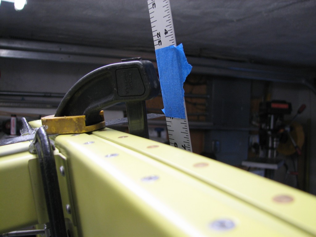
With confirmation that the rollbar was at the right height, match-drilled it to the attach brackets.
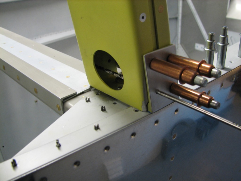
Drilling the outboard holes was easy…they’re either already pilot-drilled through existing holes in the brackets, or are drilled using holes on the F-770 skin. Drilling the inboard AN3 holes was a little more challenging. The rollbar access holes aren’t large enough to allow both holes to be drilled with an angle drill – I could get the forward hole drilled, but not the rear one. I was stumped until I realized that the lower rear outboard hole lined up nicely with the inboard rear hole, and that I could drill the inboard hole with a long bit – which is what I did, and it worked very well.
You’ll also note that I’ve tapered the outboard bracket portion so that the F-770 skin fits smoothly over the bracket. Once again, there’s not much in the way of measurement here…it’s test-fit, sand with the belt sander or file, and repeat.
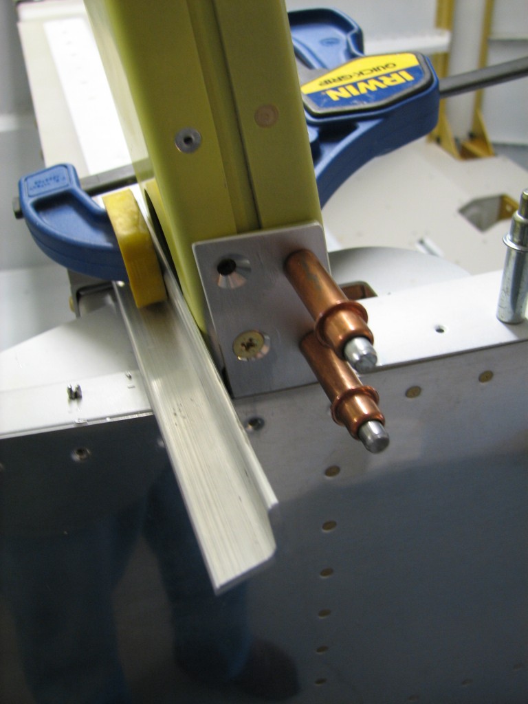
Since the side skins must fit smoothly over the attach brackets, the fastener holes must be countersunk. The rear holes are opened to #12, and fortunately I have a #12 countersink – so that made the rear holes an easy task. Once again, a normal countersink cage isn’t much good here so I had to do these freehand but they came out fine. That piece of angle clamped to the rollbar is there to provide a reference while countersinking.
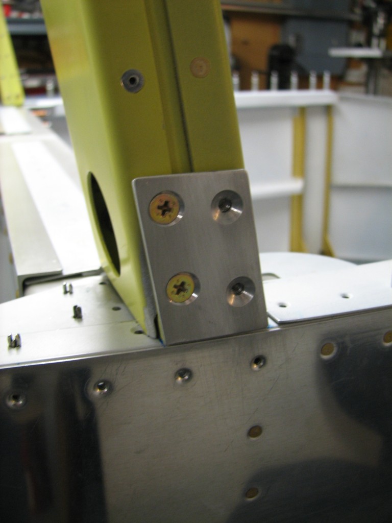
It took a lot of slow, tedious cut-and-fit work but all the countersinks came out fine.
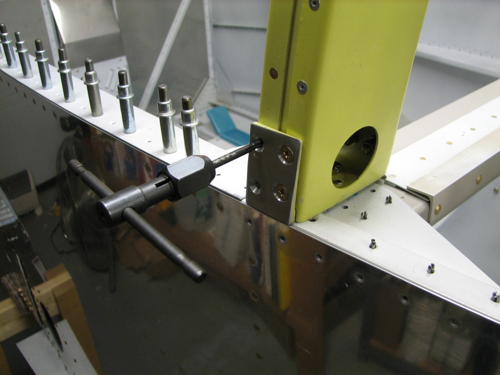
The forward holes remain drilled to #30 while they’re countersunk to accept a #8 dimple. They’re then opened to #29 and tapped to accommodate #8 screws. This is only the second time I’ve used my tap-and-die set in 9 years, but everything came out fine.
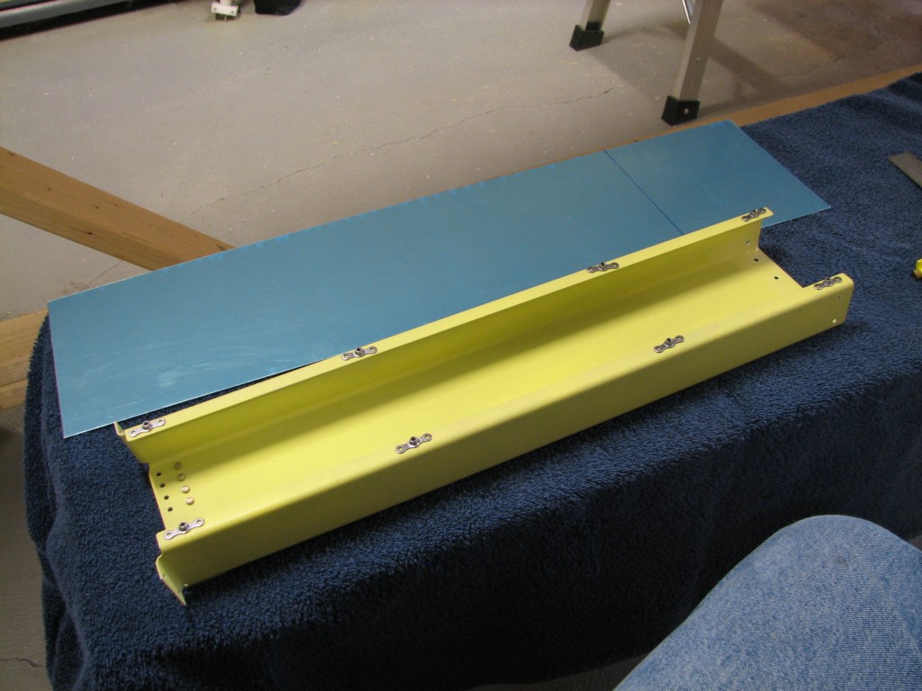
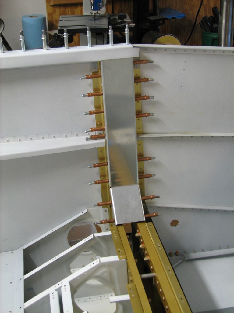
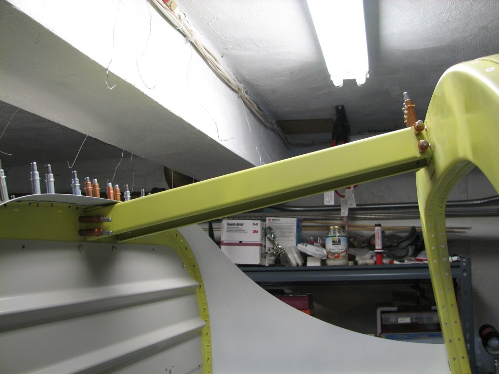 With the rollbar match-drilled, the last task was match-drilling the support channel to both the rollbar and the F-706 bulkhead. Easy to do, no issues.
And with that, the rollbar is complete. It was a slow process because I’m a picky, obsessive-compulsive builder. But in the end, it was worth all the work. Now it’s on to the forward cockpit and instrument panel.

