Even more rollbar fun…

Happy Thanksgiving!  Here’s a Turkey Day rollbar update…

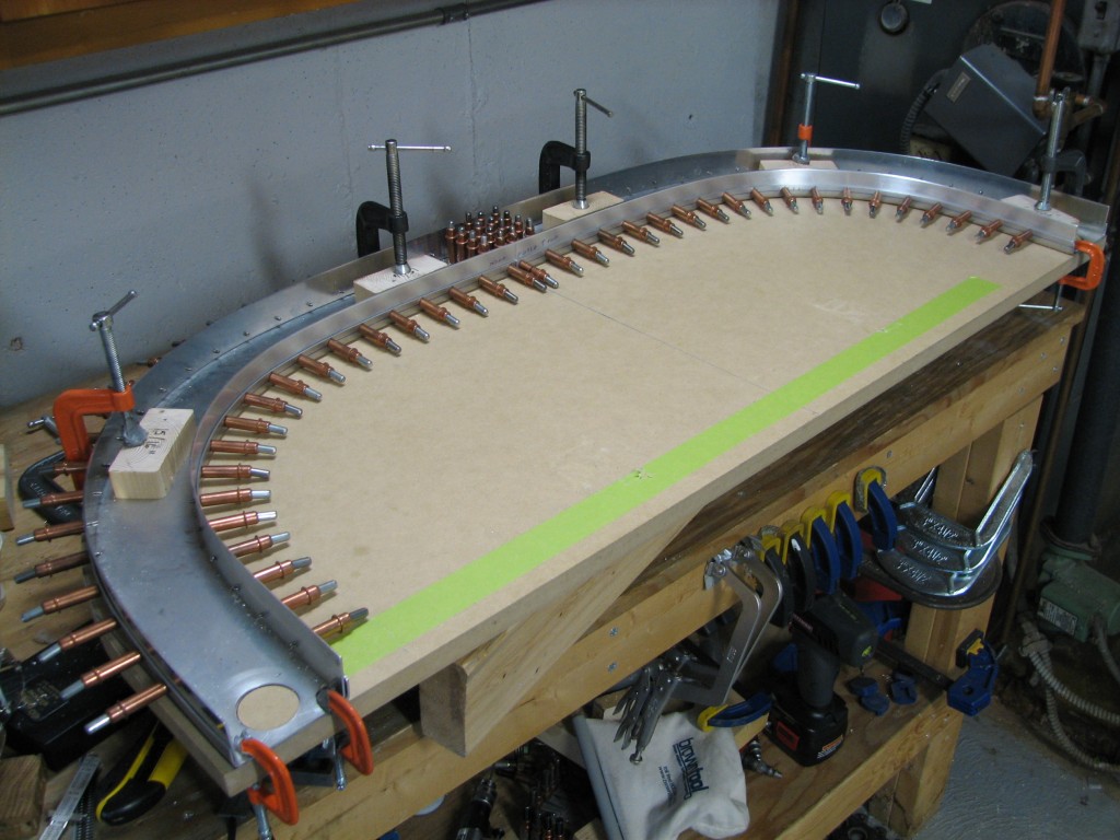
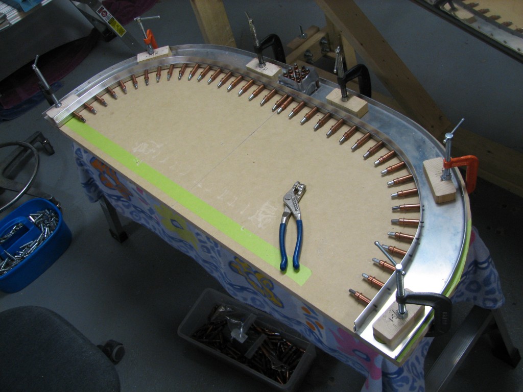
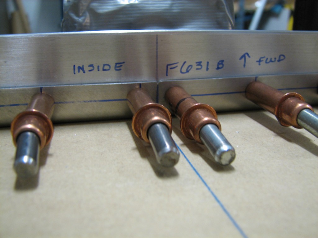
Here’s the top strap drilled into place on the rollbar’s rear half. I did it the same way as the bottom strap (see the last post). As is usually the case, this one went a lot faster than fitting and drilling the bottom strap. Sharp-eyed observers might notice that the top strap is held in place with #40 clecos…I pilot-drilled both the top and bottom straps to #40, then enlarged the holes to #30.  So there.Upper strip drilledHere’s another view of the rear channel and straps match-drilled. A thing of beauty…

Upper and lower stripsAnother picture? Sure, I knew you’d want one…enjoy!

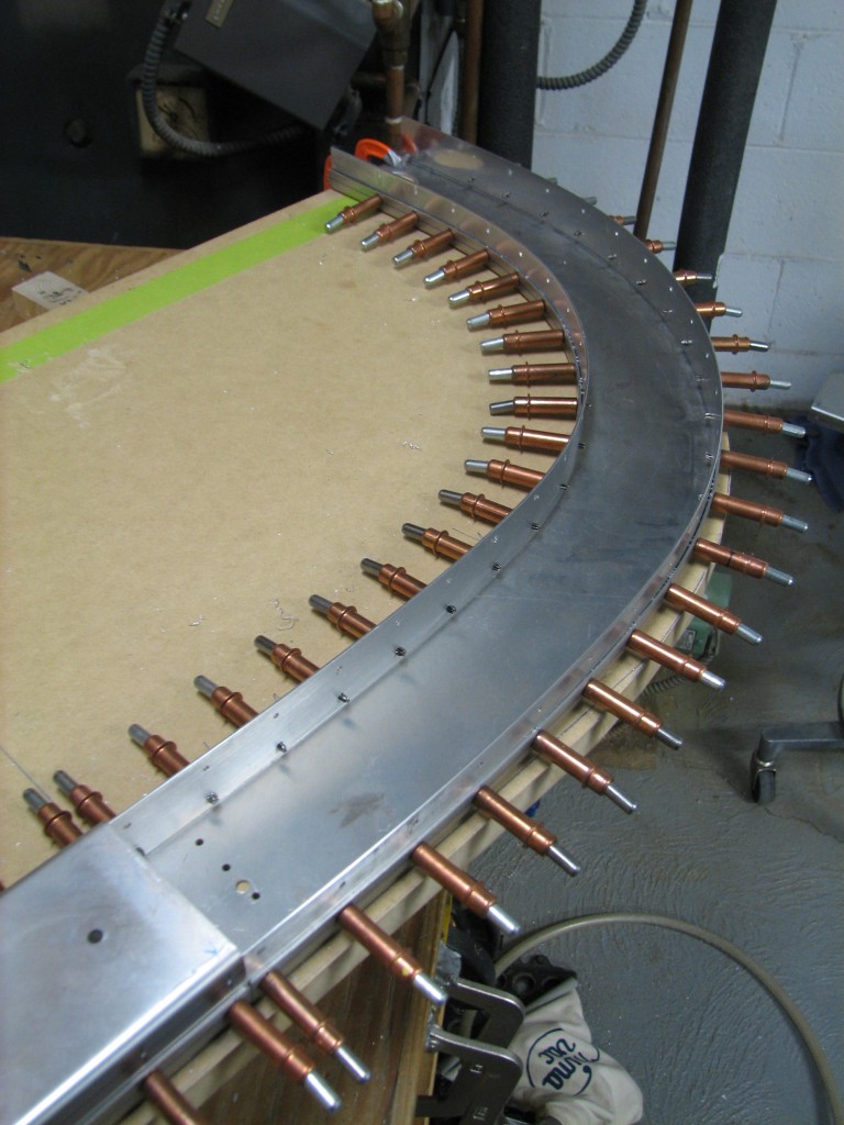
Fitting the forward rollbar halfAfter laying out and pilot-drilling rivet holes in the front channel halves, I fitted them into place on the rear channel assembly.

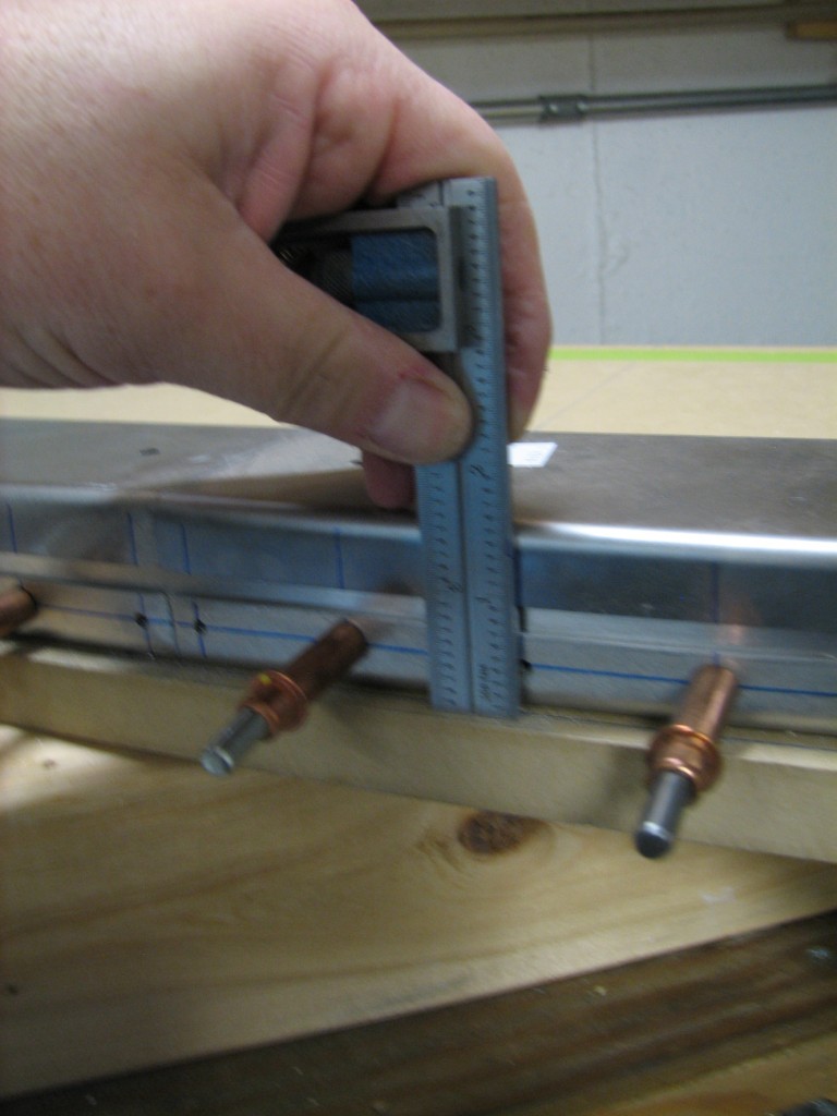
Measuring rollbar heightApologies for the fuzzy pic, but what you’re seeing is me checking the overall rollbar thickness to make sure it’s 1.5″ per plans. There’s more to follow in the next exciting installment, so stay tuned.


More rollbar fun

A quick update on the rollbar…

One of the “tricks”, if you will, of assembling the rollbar is fitting the top and bottom straps that join together the front and back rollbar channels.

The first task is to drill holes in each channel for the rivets which will eventually hold the whole thing together. Marking a rivet line with the proper 1/4″ edge distance is easily done with an edge-marking tool, but how to lay out hole locations along the curved channel halves? I followed Mike Bullock’s “masking tape” method of laying out the hole spacing on a piece of tape, then transferring that tape to the channel to use as a marking guide. I can’t describe the process better than Mike, so check out his website post for the details.

Drilling rollbar attach strips

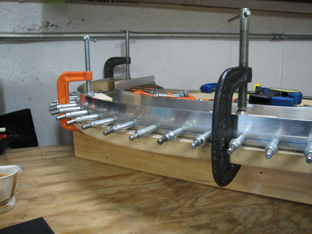
The straps, like the channels, are 0.063″ thick which makes it a minor challenge to get them clamped into place. I worked from the center to each end, clamping the strap in place after checking that it was the proper height – 1.25″ – from the back surface so that the rollbar will be the correct 1.5″ thickness. I used a lot of clamps, even had to go buy some more from the local aviation hardware store.

Here’s the end result for the aft strap…

Tie strip edge distanceVan’s didn’t bend and form the channels halves quite according to their own plans, so the edge distance on some of these strap holes wasn’t quite the usual 2d standard. But according to Gus at Van’s, the strap’s thickness gives a little margin on edge distance so I should be good to go here.


Behind the (former) Iron Curtain

In between bouts of progress on the rollbar, I took a side trip last week to Zagreb, Croatia for a work-related conference. I’ve been to Europe several times, but this is my first visit to what used to be a Soviet-bloc country. I flew through London on the way out, and our flight arrived right as a powerful and *very* windy storm tracked across southern England. Landing at Heathrow in a Delta 767-300 with winds gusting to 50 knots was a real E-ticket ride. Even after 28 years of flying little airplanes in turbulence, the low-altitude roll and pitch excursions of that airliner got my attention.

I can’t say Zagreb is the most scenic city I’ve ever visited, but the people were friendly and the beer was good. I’ve never seen a place with so many cafés, and so much nightlife.

Zagreb center

On the way back from Zagreb I flew through London again and changed planes in Heathrow’s new Terminal 5. There were several Boeing 787 Dreamliners there…very cool.

Lots of Boeings at LHR

Rolling onward

Next up after the seats is fabricating the cockpit rollbar structure.  This stout piece of structure protects the occupants (i.e. Ellen and me) in the extremely unlikely event that we find ourselves upside down on the ground.

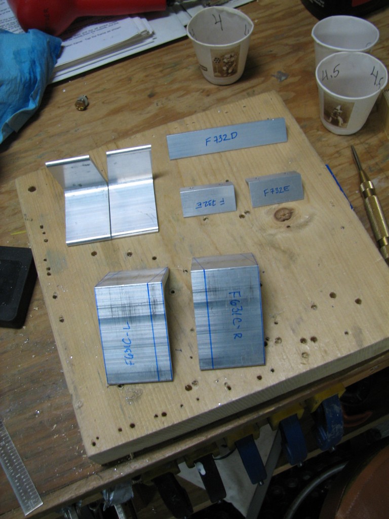
The rollbar is one of the few remaining “old school” parts from the RV-6 that Vans carried forward to the -7.  The rivet holes are not prepunched and the builder is left to lay out those holes and jig the parts appropriatelty when fabricating and drilling the rollbar.  Fabricating the angles is no big deal…just a little layout work and a few minutes on the bandsaw.

Rollbar parts

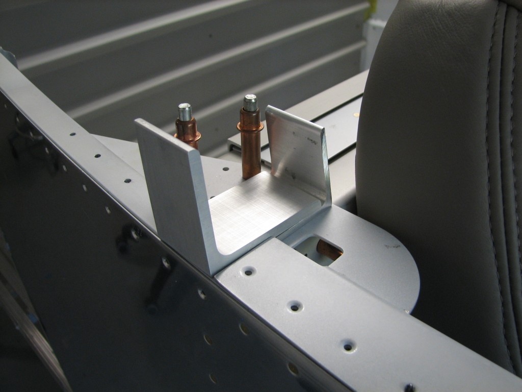
Once the rollbar is fabricated, these chunks of angle hold it in place next to the F-705 bulkhead.

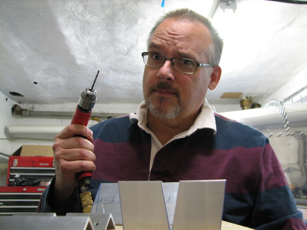
Rollbar bracketsIt struck me that there aren’t too many pictures of me in this blog.  In terms of site beautification, that’s a good thing.  But one of the main reasons for this site is to prove to the Friendly Aviation Administration that I really did all the construction work on the RV, so here’s a selfie to get my face in this post.

Proof for Uncle Shugar

Nice pic, huh?

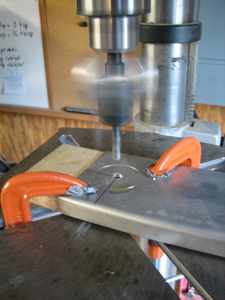
The main rollbar channels come in left/right pairs, and they’re preformed out of very stout 0.063″ aluminum.  2″ diameter holes are cut in each side of the rear channel to provide access for attachment hardware.

Fly cutter

I used the flycutter to make these holes.  Flycutters get the job done, but require some finesse to get the hole diameters just right.  Plus, the cutter itself can be pretty dangerous as you can tell from the blurry spinning mass attached to the drill press – you don’t want to get a finger whacked by all that moving stuff.

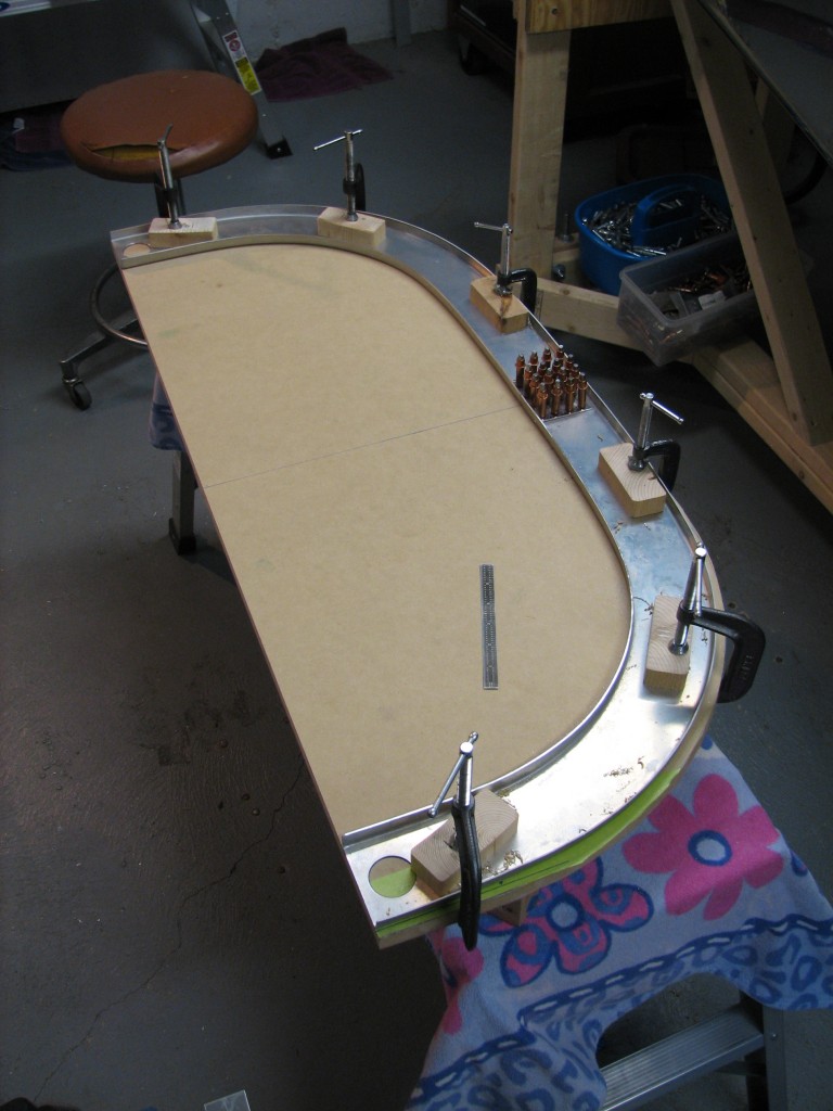
Rollbar trimmed

I laid out the maximum width and height of the rollbar on a piece of thick MDF and trimmed the inboard ends of each piece to make the width come out right, then trimmed the bottom ends of each piece to establish the correct height.  In the pic you’ll see the two rear halves clamped to the MDF board and held together by an 0.063″ doubler that I fabricated and match-drilled in place.

Truth be told, these pics are the from my second attempt at fabricating the rear rollbar half. For a variety of reasons that don’t bear repeating, my first try wasn’t so successful.  If you’re an RV builder and are reading this before you fabricate your rollbar, just remember to carefully lay out rivet spacing and edge distance.  Also, don’t worry about adjusting the flanges on the rollbar halves…that will just make it harder to get the parts to lay flat.

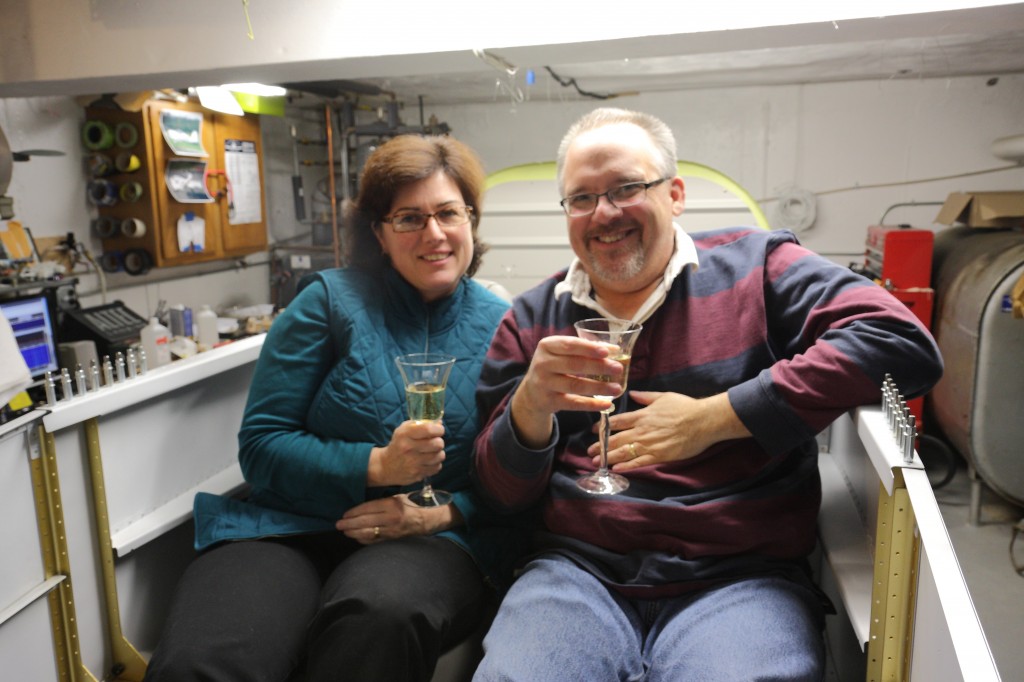
A well-deserved toast…

It’s a huge milestone to sit in your RV for the first time.  Today was that milestone for us…it’s been a long time coming and we’ve had a bottle of champagne chilling for the last couple of weeks in anticipation of this event.

A toast to seats!

Ellen remarked that the whole airplane project became more “real” to her when she sat in it for the first time. With all the riveting she’s done and the support she’s provided me, that’s good to hear.

Seats!

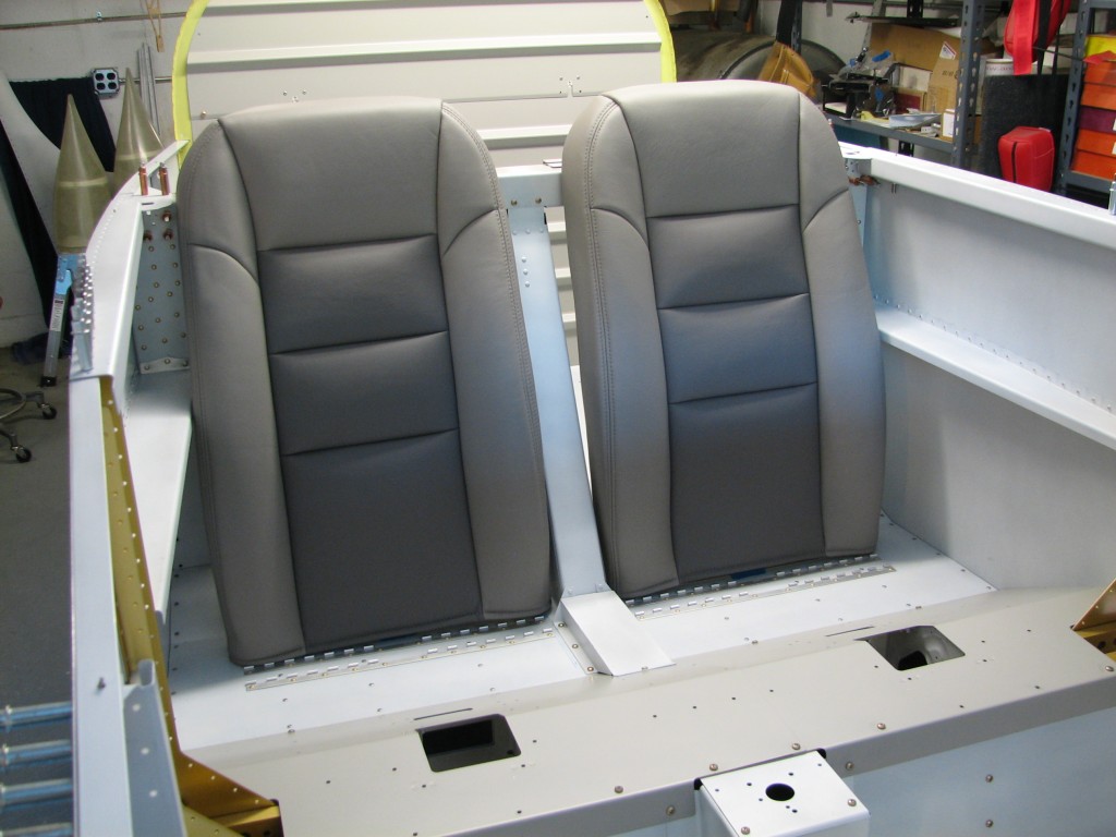
I posted some pictures a few weeks ago after we received our seats from Classic Aero Designs. With most of the interior complete, it’s time to fit the seatbacks and install the hinges that attach them to the seat floors.

Seats temp fitted

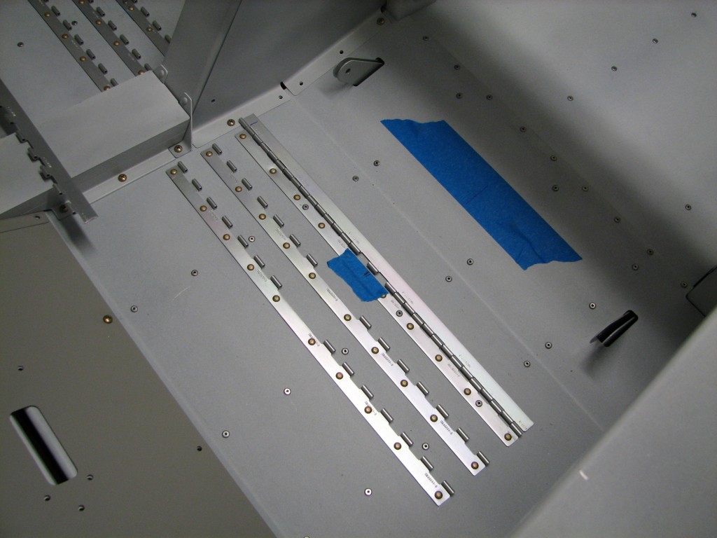
Classic Aero Designs provides comprehensive instructions for fitting the seat backs.  The most important part is adjusting them side-to-side so they don’t interfere with anything else in the cockpit. The first step in that process is finding and marking a centerline between each seat’s belt attach brackets.

Centering seat hingesI marked the center point between the seat belt brackets on the larger piece of masking tape at the rear, and I used a square to transfer that center mark to the aft most seat attach hinge. The seat backs are pre-drilled for the attach hinge rivets, and the center rivet hole is the reference for lining up the seat relative to the centerline marked on the hinge.

Once I had the seat backs where I wanted them, I marked the center rivet location on the aft seat attach hinge, and transferred that to the piece of hinge to be riveted to the seat.  Turns out that my measured centerline was within 1/16″ or so of where I had placed the seat center, so I simply used the center of the seat hinges as my reference. Some builders have had problems with the seats backs hitting part of canopy latch structure, but I lucked out – the seats fit as designed.

Installing seat hinges

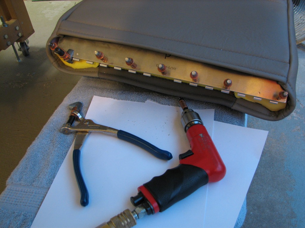
I then lined up the seat hinge centerline on the seat back’s center rivet hole, and match-drilled the hinge to the seat.  Easy peasy.

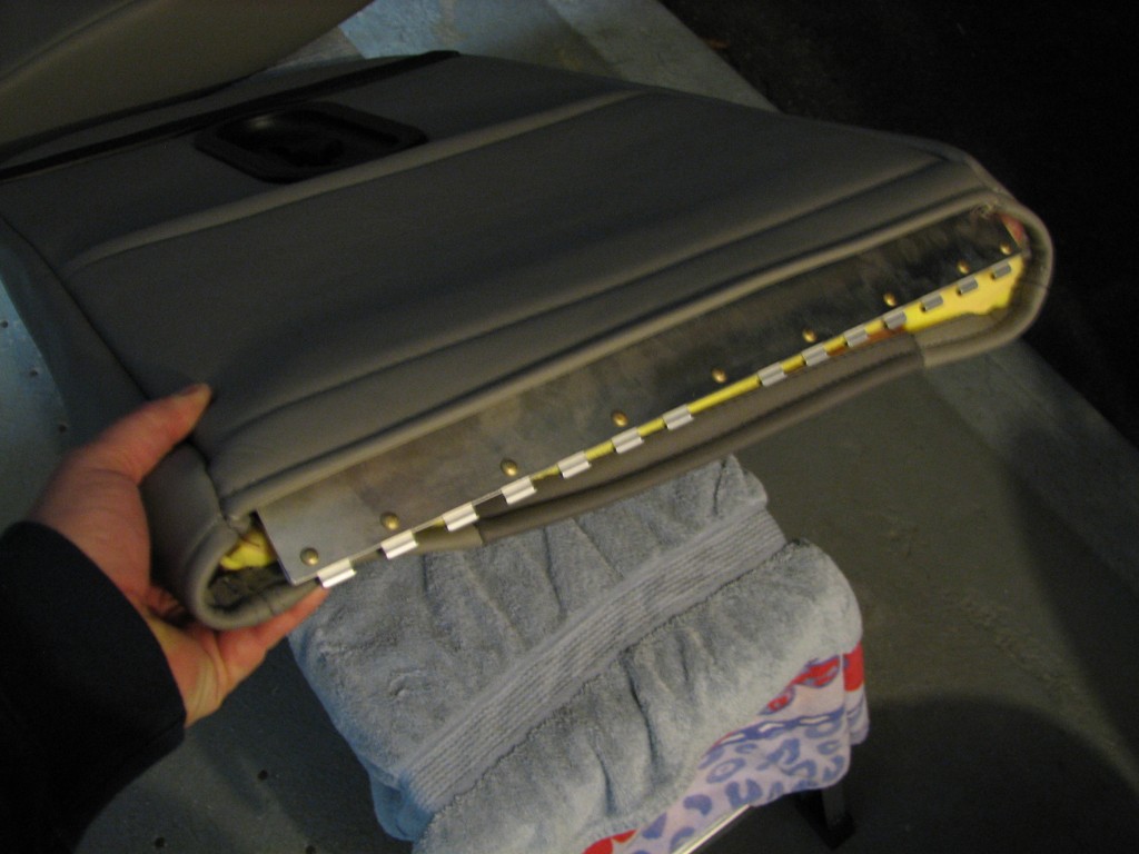
Seat hinge rivetedAfter a little deburring and trimming the hinge ends to fit inside the seat back, I riveted it to the seat…then repeated the whole process on the other seat back. I also had to fabricate some hinge pins from stock hinge wire…nothing too complicated.

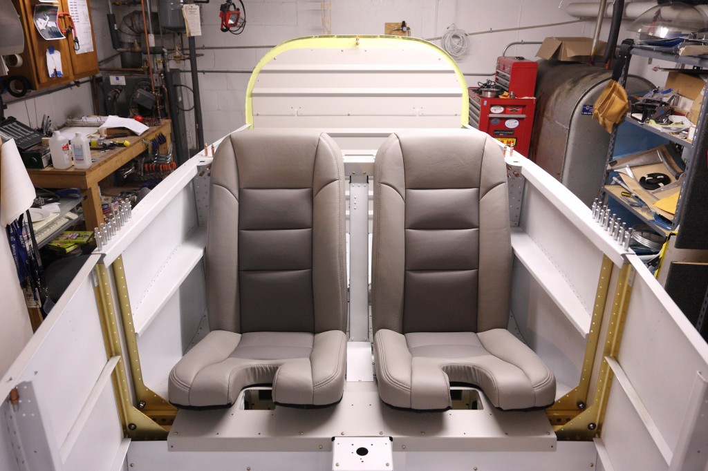
seats_installedAnd here are the seats in place, and ready for sitting.  We have a bottle of bubbly chilling in the ‘fridge to celebrate the first time we sit in the airplane!

Nutplate obsessions

Thanks to my enforced absence from work, I had a few days to finish up the flap housing and get the seats installed.

The last flap issue I had to deal with was installing two nutplates for the flap actuator tube’s center bearing block.  The bearing block is match-drilled to one of the baggage compartment ribs – it’s really difficult to spot in the picture below but if you look about halfway across the tube, you’ll see it peeking from behind the flap motor actuator arm.
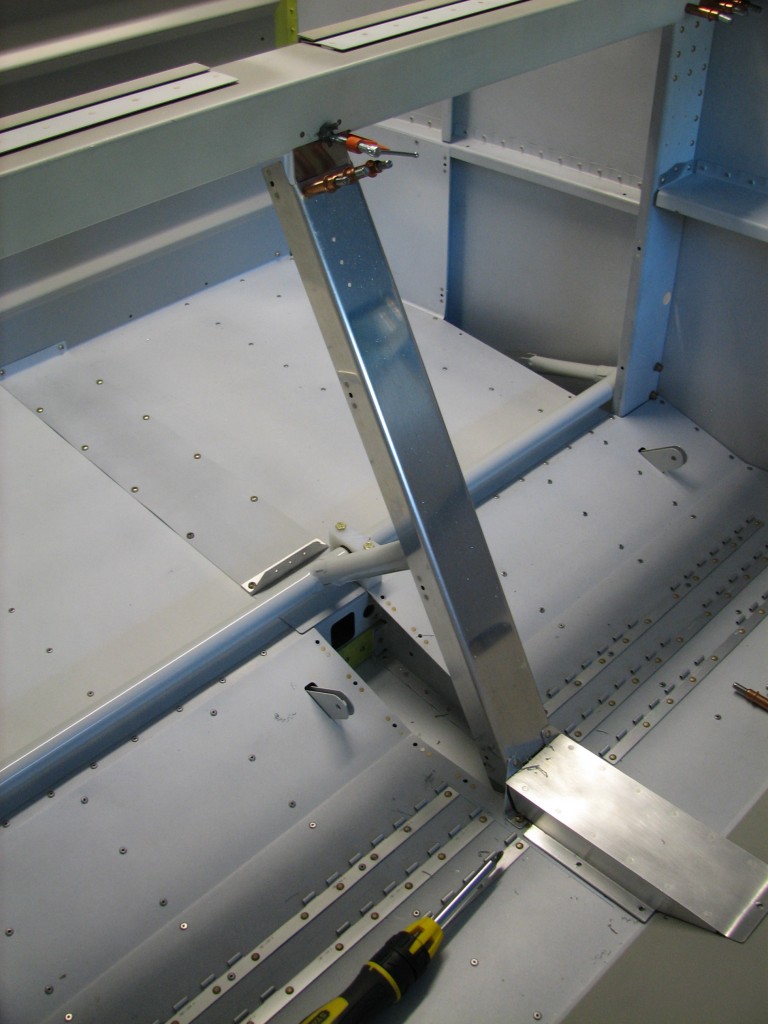
Center flap support

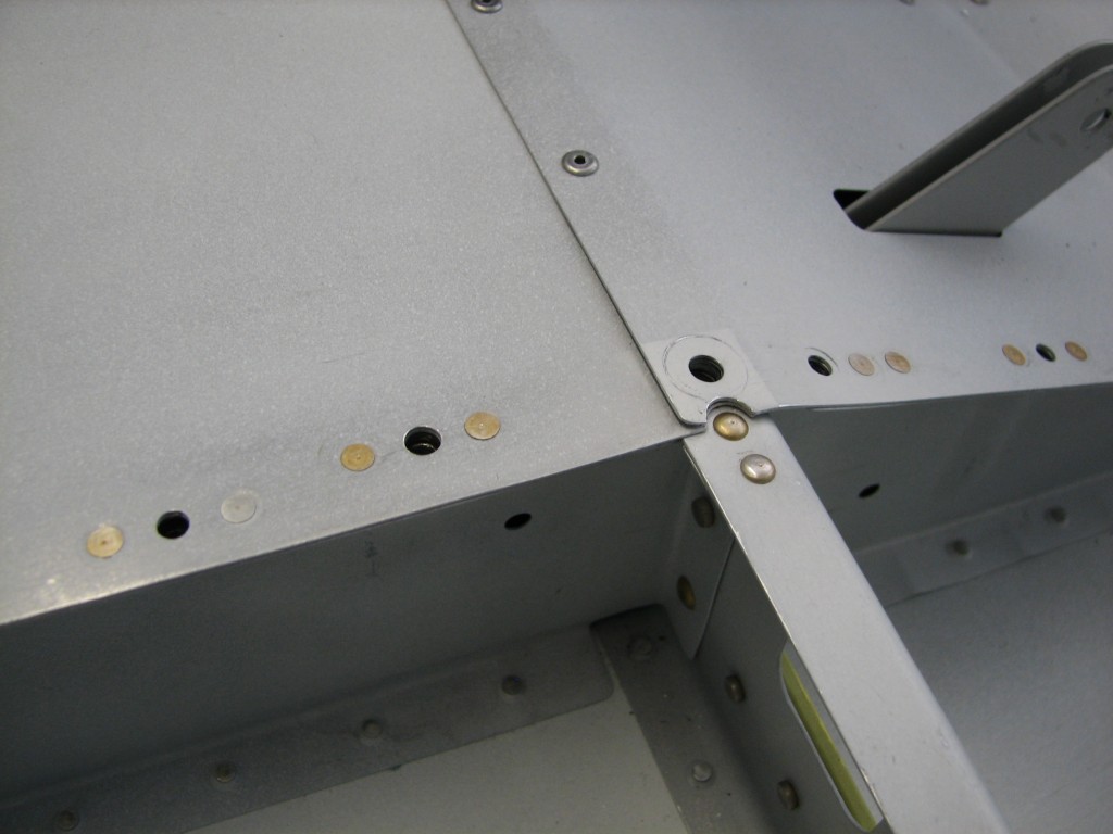
The problem with these nutplates is that they’re in a very awkward position to rivet, and the forward one has a rivet in a really bad spot – right where the seat floor ends.  I also didn’t think enough about where to place the block before I drilled the mounting holes, ’cause I could’ve moved the block a little to put the mounting holes in a more accessible location. But the deed is done and I have a problem to solve…what’s to be done?
Nutplates riveted

Jumping ahead a few steps, you can see where those forward nutplate rivets lay on the F-705 bulkhead, and how dimpling the hole closest to the bolt would have made for a very messy rivet…not necessarily unsafe, because this isn’t a particularly critical part of the plane, but that sort of workmanship I wouldn’t want others to see.

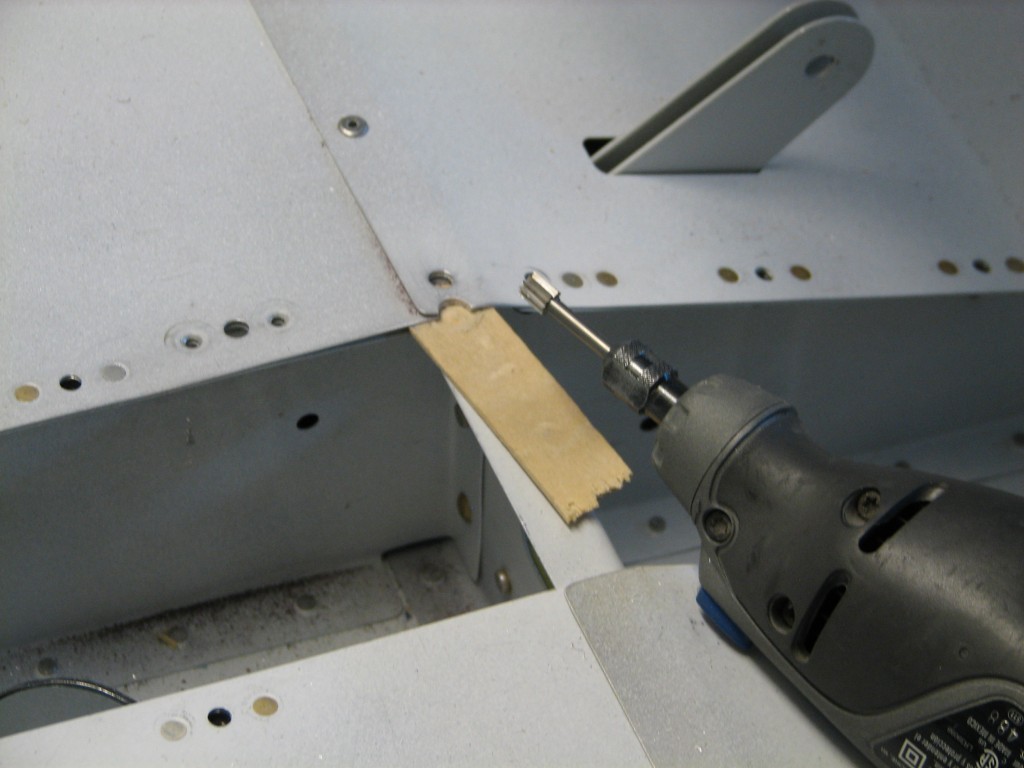
So, I elected to use some AN470-3 universal rivets I happened to have in the shop, but that meant finding a way to remove some material from the seat and baggage floors surrounding the topmost rivet hole.
Relieving rivet holes

I noodled over this one for awhile, and then decided to try a cylindrical cutting bit in the Dremel tool. But I had to find a way to protect the F-705 while using the Dremel…and a piece of tongue depressor, tapered with the belt sander so I could slide it between the floors and bulkhead, fit the bill perfectly.  If you’ve read this far, you already know it worked and I was able to get the nutplates riveted.  I also had to insert a small 0.025″ shim under part of the forward nut plate so it would lie flat across the seat rib flange.
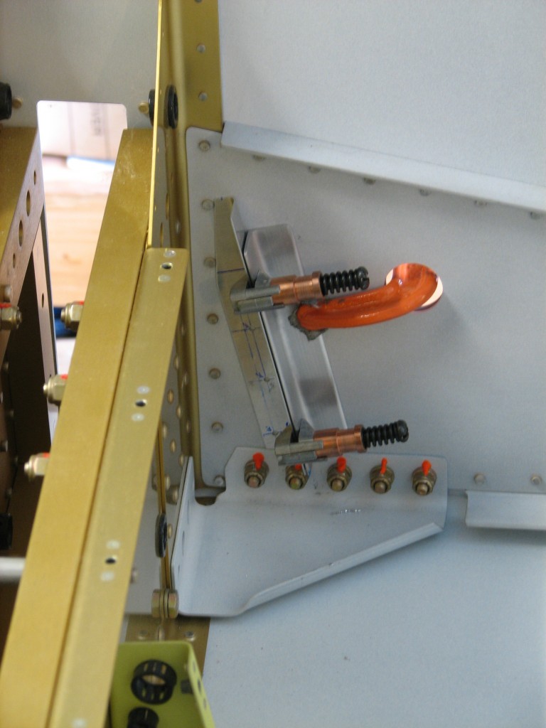
Support angles

One other task remaining was to blind-rivet the forward fuel line cover supports to the fuselage sides. I didn’t get any pictures of the supports riveted in place, but if look at the pic above you’ll see the left support clamped in place for drilling.
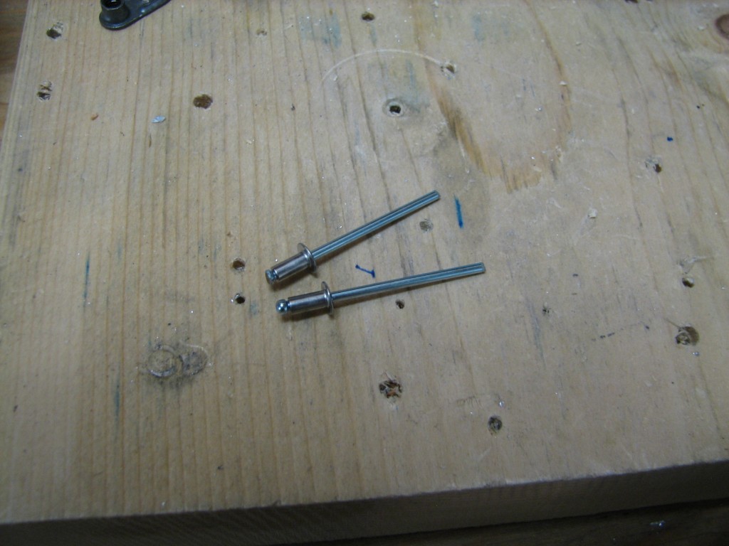
Ground-down MSP-42sThe LP4-3 blind rivets that Van’s calls for are far too long for this application, so I substituted some MSP-42 blind rivets that are both shorter and stronger. I still had to grind down the heads a little for extra room so they’d fit into the limited space behind the support and F-7101 gusset.

With those supports riveted in place, I prepped and primed all the interior parts I’ve been working on for the past few weeks.
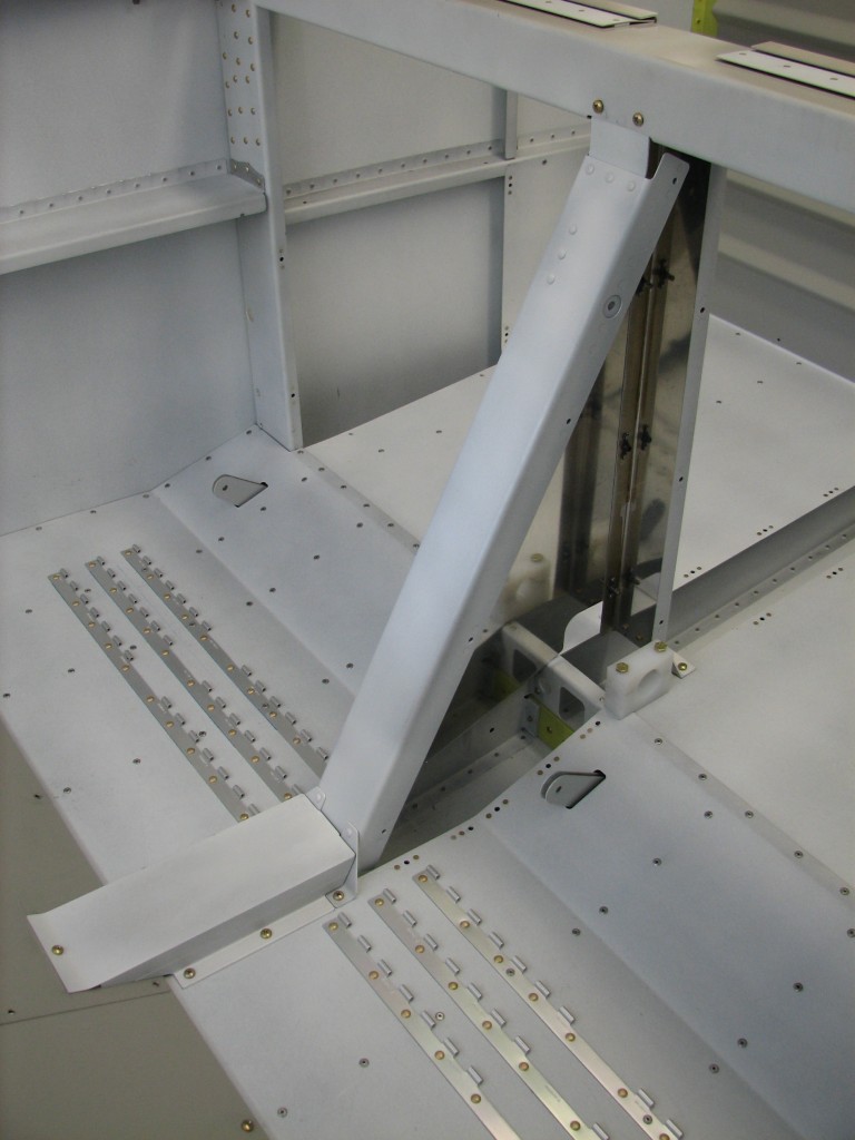
Primed flap area

Here’s the forward tunnel cover and forward/aft flap housings screwed in place.
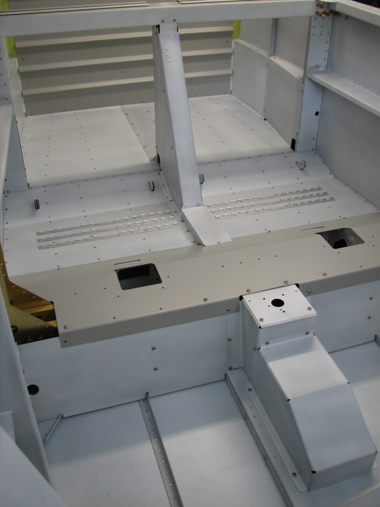
Interior parts primed and installed

And here’s the rest of the interior temporarily attached to get ready for seat fitting. Looks pretty good, I think…
 

Thanks, Ted!

I’d like to offer my sincere thanks to Ted Cruz and other far-right Republicans in the House  of Representatives for giving me extra time to work on the RV for the next few days.  Of course, I probably won’t be able to pay my daughter’s college tuition in December but life is full of little trade-offs, isn’t it?

Thanks also to Ted and his colleagues for showing us what modern democratic governance is all about.  After all, less-capable leaders would put their narrow political self-interests in reelection, and the desire to pander to their power base, above the national good by throwing the political equivalent of a tantrum.  But not you, Ted, or your Tea Party friends…good on you!

A big thumbs up to John Boehner as well for refusing to cave in to all those nasty, wrong-headed, moderate Republican turncoats who don’t see the burning need to defeat Obama at all costs…costs that include wrecking the nation’s economy, and depriving it of a functioning government infrastructure.

And finally, kudos to Congress in general for not jumping on the no-pay bandwagon after sending 800,000 civil servants home without income.  Who knows what damage would be done to the DC economy if our wealthy senators and representatives didn’t get paid? I can only imagine what the economic impact would be to Washington’s liquor stores.

Meanwhile, December will be here before we know it. Anybody need a 50-year old kidney? I’ll make you a great deal…

We have a hangar!

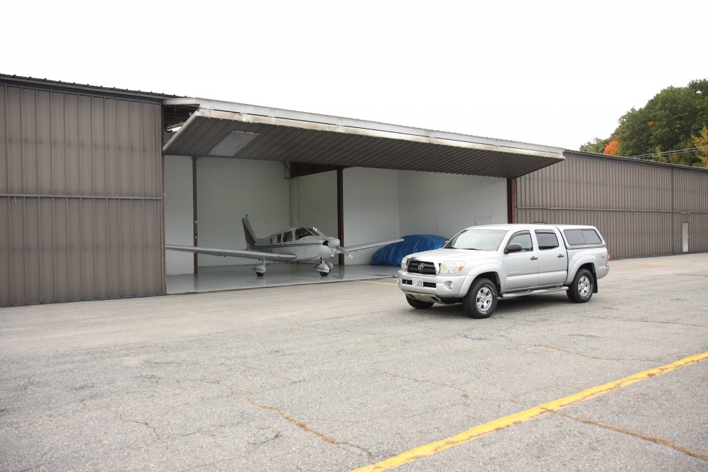
Finding a large, heated hangar for rent with compressed air to boot, that’s big enough to share with two good friends and their Piper Archer, at an airport (KASH, Nashua NH) with a great restaurant and a large RV community…how did I get so lucky?

The hangar!The hangar is big enough (50′ wide, 40′ deep tee) to have a nice workshop behind the Archer, and to accommodate the parts we’ve already finished on either side. Our landlord previously kept his MU-2 in this hangar, and with some careful arranging, I think we can get the assembled RV and the Archer in there with a little room to spare.

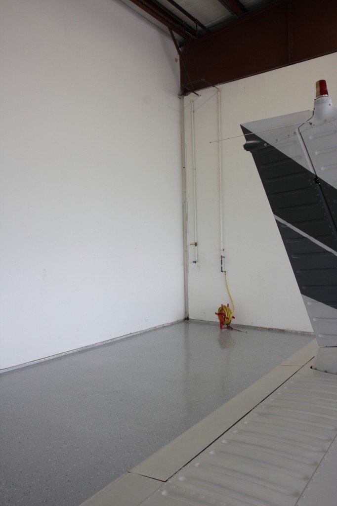
Hangar workspaceThe only downside is a bit of a commute from home and work, but it’s a small price to pay for such a good deal…

Fun with flap actuators

I had only a little time tonight to spend in the shop, but managed to get a lot done.

First, I managed to improve the fit of the flap housing sides – this is the problem I mentioned in my last post.  These things are very thin aluminum and aren’t at all structural, so I enlarged some of the screw holes to allow the part to “float” a bit when all the fasteners are in place…seems to work fine.  Sorry, I didn’t take any pictures of them after reinstallation.

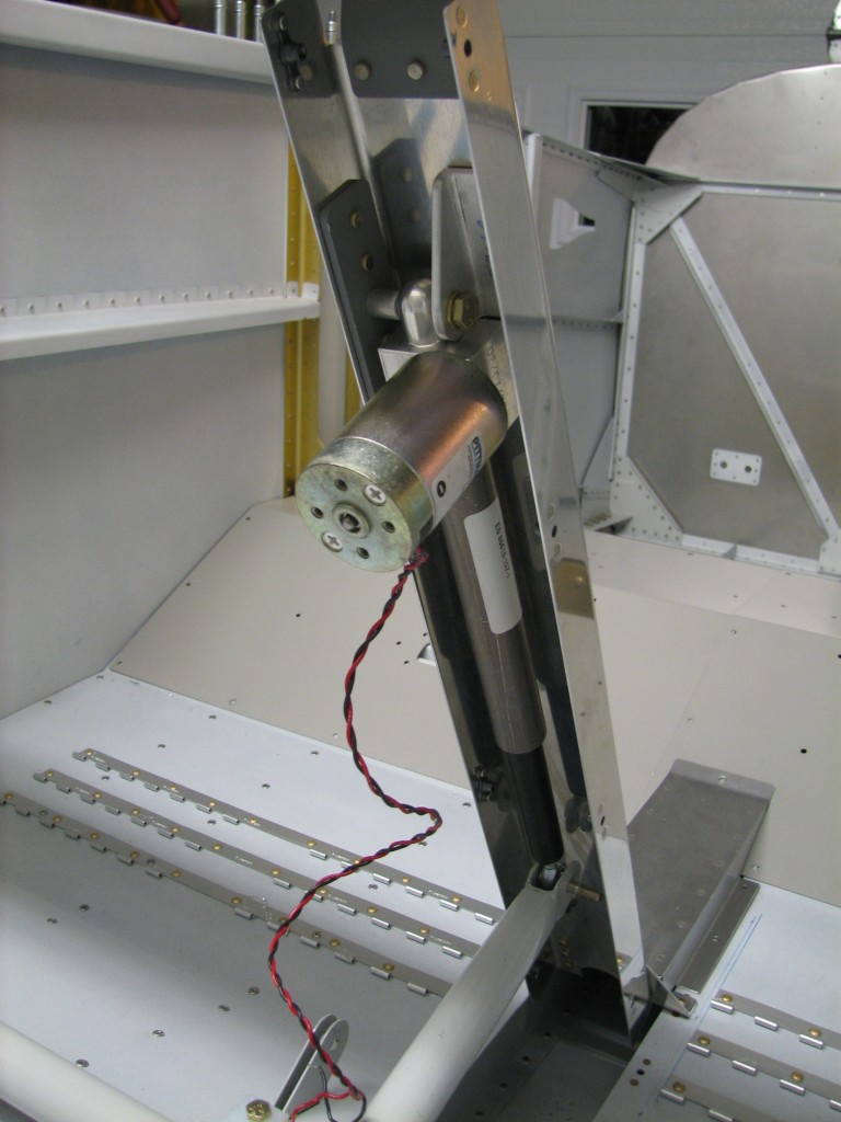
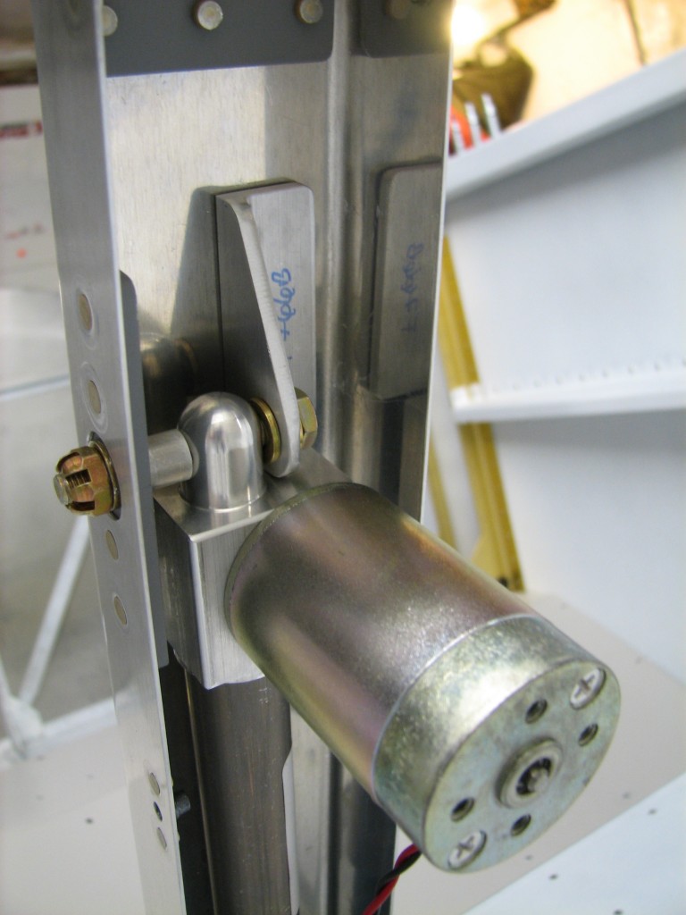
Flap motor temp fitSecond, and more importantly, I temporarily mounted the flap actuator to its housing. There’s one aluminum angle supporting the flap actuator that still needs to be mach-drilled to the forward brace – you can see the angle above and very slightly to the right of the actuator motor (for all you non-RVers, it’s the cylindrical thing with screws on the end).

Flap motor up closeHere’s a closeup of the angle.  One of the cool parts of this process is powering up the actuator with a battery to run out the actuator arm so it can be bolted to the flap arm.  The flap motor hasn’t been run in five years, but it worked fine.

With the whole angle/actuator/brace assembly in place, and with judicious application of a clamp to the angle, I’ll match-drill the angle and brace…but not tonight.  I’m whipped and it’s bedtime.